1
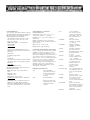
OUTPUT CHARACTERISTICS Output smoothing (filtering): The 91 01 and 9109 have built-in 18 dB/octave (3 pole Bessel) filters for P.ach channel with indepP.n dently programmable cutoff frequencies oi 100 MHz. 30 MHz, 10 MHz, 3 MHz or 1 MHz Filters may also be turned off. The 9112 is provided with one external 8-pole Butterworth low-pass filter. Cutoff fmquency (-3 dB point) 36 MHz, rolloff cc 48 dStoctave. Additional filter for 2nd channel optional External Clocking Performance ; 1 i OUTPUT CLOCKiNG CHARACTERISTICS Clock resolution: 0.035% (350 ppm). Clock accuracy: < 5 0 ppm at act1ievable set points, nt 23 'C. 115 VAC160 Hz. after a 30 minute warm-up period. Clock stability:< 0.5 ppm· C Clock jitter: 0.05% max .. 0 0125% typical. Interval range: Maximum Output Rate I I ----·! Single m1 200 Mpo111h/sec : i 200 1 I I ------·-----!---- - 5 nsec- : 20 nsec · 1 r;;; ::: - -,G;::,, ;;;; : , ;;;; : , i per channel per channel j External clocking: Output point rate may also be controlled by an external clock source. When external clocking is selected. the internal clock is bypassed and the waveform is generated using the external clock The External Clocking Performance table describes the relationship between the external clock frequency and the output point rate in various coniigurattons. External clock input impedance: 50 n. External clock threshold: Variable over the range of ±2.5 V. Resolution< 20 mV. ' 9112in I Dual Channel i Mode : I Mode I 200 M z ----2 0 Hz--1 - None .,.2 200 Mpo1nts/sec -L ----- 9112in i -z-- ! 1 <-4 · 100 Mpoints:s._e_c . 5_0_M_pointsisec -·- - - r- h n l 50 Mp:i s:!Tc I =r channel I This table describes the relationship between the external clock frequency and the output point rate m vanous conttguratJOns. 12 5;--1 ! Mpointsi:;ec 1 Mpointsisec ------- t·· 5 nsec- g ;- 1 Mode I : Single Channel +--------------- ---- Maximum Output L_S_'a_rT_1P_I:_Rat 9109in Dual Channel 200 MHz Clock F_re_q_u_e_n_cy Clock Divider 9101,9109 Single Channel Mode TRIGGERING CHARACTERISTICS Trigger Modes Continuous: The generator runs continuously at the selected frequency. Recurrent: The waveform is cycled with a programmable delay between cycles. The number of waveforms per cycle is program mabie up to 65.535. Single: Upon receipt of a trigger. the selected waveform is generated only once. The start of the v.raveform can be programrnably delayed from the trigger point. Burst: Upon receipt of a trigger, the selected waveform is generated a programmable number of tirnr;s, up to 65.535. The start of the burst can be programmably deiayed from the trigger point. Gated: The waveform is triggered by the leading edge of the gate stgnal, and stops at the completion of the waveform cycle occurring during the trailing edge of the gaie signal. Trigger delay: Programmable; limits depend on genemtor model and single or dual channel operation. The limits are given in the Tngger Delay Limits table. In the table, the term "point" indicates one sample interval's Trigger arming sources: Auto: Generator automatically rearms itself at the end of the waveform. Bus: Generator is rearmed only via command from the GPIB, RS-232 or the 9100/CP Hand held Control Panel. Triggering sources: Manual: Front panel push-button. External: External trigger applied via a front panel BNC. Bus: Trigger from GPIB of RS-232. Control Panel: Trigger key. External trigger input: Impedance: 50 n. Slope: Positive or negative threshold. Range: ±2.5 V. Threshold resolution: < 20 mV. Trigger Delay Limits I 9101,9109 f -- -----·---I • M1nirnum I Maxi I --m---- -·- Single Channel Mode 9109in 9112in 9112in Dual Channel Dual Channel Mode Single Channel Mode 4 po1nts 2 points 2 point 1 Mpoint 500 kpoints 500 kpoints ---- Mode (min.) ---+----·1-p ;-;;;--250 kpoint0 ----L--------- '