1
llllllIlllllllllllllllllllllllllIllllllllllllllllllllllllllllllllllllllllll
US005457541A
United States Patent [191
[11] Patent Number:
Burns
[45]
[54] METHOD AND APPARATUS FOR
CALIBRATING IMAGE OUTPUT FROM AN
IMAGE GENERATING DEVICE
Date of Patent:
5,457,541
* Oct. 10, 1995
OTHER PUBLICATIONS
Desktop to Press, vol. 1, No. 5 (Mar. 1990).
Linotronic 300/500 Cora Operation Manual-issued Apr.,
1987-Copyright 1987.
[75] Inventor: James M. Burns, Austin, Tex.
Linotronic 300/500 R Imagesetter Interface Manual-issued
[73] Assignee: Southwest Software, Inc., Austin, Tex.
Feb., 1988-Copyright 1988.
Series 2000-Graphics 2000 Linotype sales brochure-printed
Feb., 1988~Copyright 1988.
[*1 Notice:
Series 2000-Graphics 2000 User Manual-issued Mar,
The portion of the term of this patent
subsequent to Sep. 14, 2010 has been
disclaimed.
1989-Copyright 1989.
Listing of an “Aldus Printer Description File” (Jun. 9, 1988).
Aldus Preprint Program User’s Guide (Main, 1990).
Adobe Photoshop Program User’s Guide (Feb., 6, 1990).
[21] Appl. No.: 87,220
[22] Filed:
Color Studio User’s Guide and Retouching/Separation
Package (Mar, 6, 1990).
Jul. 2, 1993
Color Calibration Software for Postscript Image Setters
(Feb., 22, 1990).
Related US. Application Data
[63]
(List continued on next page.)
Continuation of Ser. No. 909,731, Jul. 7, 1992, Pat. No.
5,245,443, which is a continuation of Ser. No. 592,022, Oct.
2, 1990, Pat. No. 5,170,257.
[511
Int. Cl.6 ............................. .. H04N 1/00; H04N 1/23;
[52]
US. Cl. ........................ .. 358/298; 358/406; 358/455;
Primary Examiner--Benjamin R. Fuller
Assistant Examiner-Eric Frahm
Attorney, Agent, or Firm-Arnold, White & Durkee
H04N H40
An improved method and apparatus for calibrating halftone
output images is provided which calibrates subsequent half
tone input images with varying imagesetter outputs such as
358/456
[53]
Field of Search ................................... .. 358/298, 406,
358/455-461, 518, 525, 214; 346/108,
160; 395/107, 109
image resolutions, exposure intensities and screen frequen
cies. Calibration is programmably achieved by programma
bly selecting a speci?c calibration set for each correspond
ing uncalibrated halftone input image. The selected
calibration set and mapping transfer function automatically
compensates or adjusts the uncalibrated input image for any
References Cited
[56]
U.S. PATENT DOCUMENTS
4,004,079
1/1977
Boston .................................. .. 358/302
Gall
4,075,662
2/1978
4,314,281
2/1982 Wiggins et al.
.... .... . . ..
4,500,919
4,757,334
2/1985
7/1988
. . . ..
358/280
358/78
354/76
4,833,627
4,903,141
5,157,482
5/1989 Leszczyaski
2/1990 Morton et al. ..
10/1992 Cosgrove
. 395/145
358/448
. 358/214X
5,170,257
12/1992
. . . ..
.. ... ....
5,170,261 12/1992 Cargillet a1.
358/298
358/518
12/1992 Collette et a1. .
9/1993
photographic medium. Once the calibrated halftone output is
programmably produced, it can then be photoprocessed
according to conventional chemical processing means. The
present invention represents a substantial improvement in
precision and speed by which halftone output images are
calibrated in the typeset industry.
358/298
5,172,224
5,245,443
value of resolution, intensity and screen frequency to pro
duce a calibrated halftone output image in either positive or
negative sense output and usable on either paper or ?lm
358/280
Schreiber ..... ..
Volent ...... ..
Burns
ABSTRACT
[57]
12 Claims, 3 Drawing Sheets
Burns .................................... .. 358/298
46
(
5/
new;
55
Q
Ski
85$
E“
t
l
is 1I
32
33 34
I|
37,4 [gig/f, WINK/77g:
3:;
l
4/
F
2550mm
5,457,541
Page 2
OTHER PUBLICATIONS
LinoCal 1.0 a/k/a Calibration Utility of Linotype—Hell cor
responding to the calibration presently employed in later _
cover pages, pp. 178-179, 306-309, 312-320, 499, 505
(1990).
versions of the Linotype-Hell utility program such as utility
QMS ColorScript 100 Model 30i User’s Guide, cover page,
pp. i, 11-1 to 11-5, 11-9 to 11-10 (1990).
6.0 and 7.0.
Color Calibration Software by Technical Publishing Ser
vices, Inc.
Feb. 1988—Copyright 1988.
Series 2000—Graphics 2000 User Manual-issued Mar.
Kita Calibration System for Linotr0nic—May 1989.
Goertzel, G. and Thompson, G., “Digital halftoning on the
1989-Copyright 1989.
IBM 4250 Printer”, IBM J. Res. Develop. v01. 31, No. 1
(1987).
Webster, J., “Radius opens color calibration system”,
MacWeek (1990).
Postscript Language Reference Manual—Aug. 1986.
Postscript Language Reference Manual, Second Edition,
Series 2000—Graphics 2000 Linotype sales brochure-printed
Linotronic; 300/500 R Imagesetter Interface Manual-issued
Feb, 1988-Copyright 1988.
Linotronic 300/500 CORA Operation Manual-issued Apr.,
1987 Copyright 1987.
Aldus Printer Description File (reference AF ?led by Burns
with Information Disclosure Statement).
US. Patent
0a. 10, 1995
Sheet 2 of 3
5,457,541
5,457,541
1
2
METHOD AND APPARATUS FOR
CALIBRATING IIVIAGE OUTPUT FROM AN
IMAGE GENERATING DEVICE
photographic paper is used, density is the measure of how
much light is not re?ected. Higher density values correspond
to a “blacker” piece of ?lm.
These ?lms are typically used in the publishing industry
to make contact printing plates. For reasons of quality and
This is a Continuation of application Ser. No. 07/909,
731, ?led Jul. 7, 1992, now US. Pat. No. 5,245,443 which
ease of production in printing plate manufacture, it is
in turn is a continuation of Ser. No. 07/592,022, ?led Oct. 2,
1990, now U.S. Pat. No. 5,170,257.
BACKGROUND OF THE INVENTION
desirable that the maximum density measurement on a ?lm
be in excess of 4.00. The maximum density available is a
10
function of the light source intensity, the photographic
medium and the process and chemicals used for develop
ment.
Incorporated herein is a computer program listing printout
Since conventional printing processes cannot reproduce
appendix of source code used to generate calibration sets
and calibration transfer functions of a test pattern to enable
continuous tone tints or images, gray scales (tints) and
halftones are approximated in page description languages by
calibration of halftone output images according to the
present invention. Copyright, 1990, Southwest Software Inc.
A portion of the disclosure of this patent document contains
material which is subject to copyright protection. The copy
right owner has no objection to the facsimile reproduction
by anyone of the “Program Printout Appendix”, as it appears
overlying a halftone grid on top of the recorder’s pixel grid.
The halftone grid, often called a screen, is speci?ed by the
number of halftone cells per inch (or lines per inch) and the
angle from the vertical by which the halftone grid is rotated.
Each cell of the half tone grid encompasses a speci?c
in the Patent and Trademark O?ice Patent ?le or records, but
tone image is simulated by assigning a gray value to each
otherwise reserves all copyright rights whatsoever.
halftone cell contained within the image. Thus, imagesetters
number of pixels of the recorder’s pixel grid. A continuous
which use PostScript® are unable to produce shades of gray
This invention relates to a method and apparatus for
calibrating halftone output images from an imagesetting
device. In particular, the present method and apparatus
comprises steps and devices involved in producing a plu
25
directly, generally approximate shades of gray by utilizing
the aforementioned halftone technique. Halftone grids over
lying the top of the pixel grids allows for a shade of gray to
rality of calibration sets and in using those calibration sets to
be approximated by turning a certain percentage of pixels
adjust the uncalibrated halftone input images to produce
on. The gray value of the halftone is obtained by averaging
the gray continuous tone values contained within the dimen
sional boundaries of the halftone cell. Each halftone cell
approximates a shade of gray by turning on, in dot shape, a
certain percentage of the pixels contained within the cell. As
the cell needs to be darker, more of the pixels are turned on.
Theoretically, a 50% gray tint is made by turning on 50% of
the pixels in a half-tone cell. These conventional techniques
calibrated output images as a function of image resolution,
exposure intensity and screen frequency. Further, the cali
bration sets can be generated to produce halftone output
images on either ?lm or paper and for either positive or
negative representation of the halftone input image.
Typically, there are four fundamental steps involved in
producing typeset-quality output from a computer front end
publishing system such as, e.g., a PostScript imagesetter (or
typesetter). First, an application program (a drawing or page
layout package) is used to ?nd what is wanted or actually
printed on the paper or ?lm. Second, the “print” option from
the program is used to start the printing process. Typically,
35
are well known in the art.
Associated with halftones is the problem commonly dis
covered by densitometers. A densitometer is a scienti?c
instrument that measures density, or the ability of a piece of
?lm to block light. The blacker the ?lm, the more light it
the print option translates what is seen on the screen into a
absorbs, and the higher the density reading on the densito
page description language that the imagesetter can recog
nize. The page description language is what is then sent to
meter. When measured with a densitometer, a halftone area
the imagesetter.
Many conventional imagesetter systems consist of raster
image processors (RIP) and recorders. An exemplary RIP is
one sold under the Model No. RIP-30 by Linotype Company
of Hauppauge, NY. The RIP performs the third step in the
process by converting the page description language sent to
it from the front end into a raster or a grid of lines. Each line
contains a series of pixels, which can be considered as a list
of dots which turn on or off to form the image. In the fourth
step, the RIP sends this raster to the recorder, which uses a
that was supposed to be 50% gray will typically (for paper
45
positive) be darker, because the higher exposure intensity
needed for a higher maximum density (Dmax) tends to
expand the pixel size, causing the overall halftone-dot to be
larger than it actually is. Thus, halftone images, when
uncalibrated, produce a gray value which is typically darker
50
than that which the gray value should be. That is, when 50%
of the pixels within a halftone cell are exposed, the resulting
dark area covers more than 50% of the area contained by the
halftone cell At a dot area value of 0%, none of the halftone
cell’s pixels are exposed; at 100% dot value area, all of the
modulated light source to expose the image onto either 55 pixels are exposed. Both 0% and 100% are always obtain
able, therefore a non-linear relationship exists between the
photographic ?lm or paper. An exemplary recorder is one
commanded dot area (or gray value) and the dot area
sold as Model No. Linotype-330, also by Linotype Com
actually achieved. A series of tint boxes in 5% intervals
between 0% and 100% is commonly called a “gray scale”.
cassette, is then removed from the recorder and photo
The non-linear response of the gray scale is a function of
developed by a conventional chemical process.
60
pany. The photographic medium, in a light~tight takeup
All imagesetters have a light source intensity adjustment
the resolution of the recorder pixel grid, the light source
intensity, the photographic media (?lm or paper) and the
provide proper exposure of the ?lm. Exposed areas turn
screen grid. These, however, are not the sole contributors to
black on both photographic ?lm medium or paper medium
gray scale non-linearity. Contributing factors include the
after development. The amount or degree of blackness,
called “density” is a function of how much the ?lm is 65 recorder light source, different ?lm batches and photopro
cessor chemicals.
exposed. Strictly speaking, density is a measure of how
Page description languages referred to hereinabove usu
much light is blocked by a piece of ?lm. Conversely, if
5,457,541
3
4
ally contain a mechanism to correct for non~1inearities in
application, per imagesetter would be required. This is
gray scale and halftone output. An exemplary page descrip
typically the case for closed reproduction systems, such as
that mentioned in US. Pat. Nos. 4,075,662 and 4,500,919.
The limitation on output conditions, however, is unrealistic
tion language is one sold under the trade name PostScript®,
by Adobe Systems Inc. of Mountain View, Calif. The
mechanism Adobe included in PostScript® is called the
“transfer function”, and it provides the lowest level means to
and impractical with multi-function RIPs and imagesetters
such those used in Model Nos. RIP-30 and Linotronic-330.
calibrate the imagesetter to correct for non-linear gray scale
A typical production environment using this equipment may
response. Postscript® transfer functions suffers an important
disadvantage in not having the ability to compensate for all
require 24 transfer curves, for 5 applications, for 2 imag
the numerous variables which typically cause the non-linear
response, e.g., resolution variation in media, resolution,
screen frequency exposure intensity, etc.
Not only are conventional imagesetters, and transfer func
tions therein, lacking in necessary complexity so as to
compensate for numerous variations in, e.g., the resolution
of the image to be calibrated, the exposure intensity of the
to-be-developed image, the screen frequency, etc., but con
ventional devices also cannot produce precision transfer
10
to manage.
The second method by which conventional calibration
adjustments are made, or RIP-based calibration, was formed
as an attempt to reduce the number of curves and ?les
required to support a minimum of output ?exibility. Thus,
functions applicable to color image processing. Current
imagesetters are black and white devices and “process
color” reproductions are produced by overprinting the col
20
ored inks yellow, cyan, megenta and black. The colors of an
image are “separated” into yellow, cyan, megenta and black
components and are then outputted on black and white ?lm
in precise percentages. The ?lms, called color separations,
represent the amount of process color needed in each‘ area of
the page, and are used to make the printing plates. The
esetters. This would yield 240 separate transfer curves
(24><5><2=240). If these curves were distributed among four
front ends, then the operator would have to manage 960
separate ?les. In practice, the number of transfer curves used
is a balance of output ?exibility versus the number of curves
25
RIP-based calibration is an approach used to calibrate the
RIP and the imagesetter as a unit, so that all front ends and
all application programs assume the device produces a linear
gray scale. This process requires an operator to construct a
transfer curve under identical output conditions to the
present, and to properly identify and select that curve for use
in the RIP and imagesetter. In the existing art, the operator
loads the single curve into violative memory within the RIP.
This is not repeated for each application programmable front
end. In our example, this has the net effect of reducing a
number of transfer curves needed from 240 to 48, and the
imagesetter produces black and white, and the ink used with
the ?nal printing plate produces color. The RIP and imag
esetter mechanism that produces tints and halftones also
produces color separations. The key difference is that each
number of ?les from 960 to 48. Although RIP-based cali
bration is effective in reducing the number of transfer
curves, current RIP-base calibration techniques do not uti
lize many of the variable inputs which can effect the transfer
curve. Furthermore, conventional RIP-based calibration
color separation is rotated with respect to the others and its
respective line per inch speci?cation is slightly different.
The rotation and change in lines per inch speci?cation
avoids the dots lining up in a moire pattern. While gray scale 35 requires manual selection and loading of the transfer curve
appropriate to the current output conditions. Manual selec
calibration is mostly insensitive to rotation, it is a function
tion and loading for each transfer curve is not only ine?icient
of the halftone lines per inch.
but dif?cult to incorporate and thus, it is errorprone.
Gray scale calibration is well known in the industry. A
Accordingly, current calibration methodology requires
series of pre-determined gray scale tint boxes, at pre
that separate transfer curves be constructed to account for
determined dot areas, are requested of the RIP and imag
esetter, through the page description language, and each tint
the plurality of variable inputs. Included with those inputs is
box on the resulting ?lm is measured with a dot-area
densitometer described hereinabove. The resulting measure
ment, called a “transfer curve” is then used to adjust the
requested dot area by an amount necessary to achieve 45
either positive or negative output sense conditions. Images
can be outputted in either a positive or negative format, one
format or sense being the inversion of the other. Images,
lines and type in a page description language are usually
speci?ed from the front end in a positive sense. The RIP and
calibrated output.
However, as mentioned above, conventional transfer
curves suifer many inherent disadvantages. Existing art
divides the method in which the gray scale calibration
adjustments are effected into two categories: application
imagesetter can output any positive sense, or can switch to
a negative independent of the page description. The negative
sense is useful in many printing processes. Conventional
50
methods for specifying a negative output sense are as
based gray scale calibration, an attempt is made to compen
follows:
1. Mathematically, through the transfer function and its
sate for the non-linearities by sending an adjusted transfer
interaction with the page description language. This method
program-based and RIP-based. In application program~
converts a gray value to negative by subtracting the gray
tedious and error prone because it requires an operator to 55 value from 100 prior to halftone dot generation. Hence, a 0%
gray value becomes 100%, 25% becomes 75%, etc.
construct a transfer curve under identical output conditions
to the present, and to properly identify and select a speci?c
2. Electronically, by inverting the pixel stream in the RIP
curve to be sent with the print job. This process is duplicated
prior to it leaving the RIP. A gray value is converted to a
for each application program, and for each imagesetter. If
raster-based halftone dot, the halftone dot is placed in the
there are multiple front ends sending the imagesetter print 60 RIP’s raster memory, and after the complete page descrip
jobs, then the ?les containing the curves must be distributed
tion is progessed, the raster memory is transferred from the
and managed. The number of transfer curves can become
RIP in serial fashion to the recorder. Each bit in the pixel
unruly. In an effort to reduce the number of transfer curves
stream is inverted; that is, if the bit were on, it is turned o?,
required, conventional methods require limiting the number
if the bit were off, it is turned on. This produces a negative
of output conditions which can be speci?ed. For instance, if
image, but because it has the effect of “turning the halftone
?lm negatives at high resolutions of 150 lines per inch was
dot inside out” the transfer curve required to produce the
the only output condition, then only one transfer curve per
negative calibrated output is substantially diiferent from that
curve immediately before the print job. This process is
5,457,541
6
5
halftone images further includes storing the calibrations sets
in a local memory medium and programrnably retrieving a
used with the mathematical negative.
3. Electronically, by inverting the pixel stream in the
selected calibration set so as to convert the subsequent
recorder immediately after it enters the recorder. This
method is substantially similar to the second method above,
halftone input image to a calibrated halftone output image.
Conversion, or calibration, can compensate for variation in
and uses the same transfer as the second method in order to
the imagesetting device’s current settings of image resolu
calibrate.
In practice, these methods are multiplicate in nature. That
tion, exposure intensity and screen frequency. The calibra
tion method can also calibrate depending upon whether or
not the calibrated halftone output image is to be positive or
negative or is received on either ?lm or paper photographic
is, each of the three output sense settings shown above are
set either positive or negative, and combine to produce an
image. The negative of a negative is a positive. For example,
the ?rst method shown above places the output sense setting
as positive, and the second and third method each set output
sense setting as positive and the resultant image is positive.
However, if method one places sense setting as negative, but
medium.
As a further embodiment, the present invention also
contemplates a method of calibrating halftone output images
from an imagesetting device comprising providing a half
tone input image with requested gray value densities,
wherein each gray value density is a function of image
resolution, exposure intensity and screen frequency of the
input image. The uncalibrated halftone input images are
method two places sense as negative and method three as
positive, the resultant image is also positive. The transfer
curve for these two cases, however, are different and this
must be recognized by the operator for successful calibra
chemically processed and thereby exposed on photographic
tion. Thus, regardless of which method is used or whether or
medium so that they can be measured by a densitometer. A
not the methods are multiplicated such that more than one
plurality of calibration sets are then generated corresponding
to the variation between the requested gray value density
and the density measured by the densitometer for each
halftone input image and at varying values of image reso
lution, exposure intensity, screen frequency and photo
graphic medium which is to receive the resultant halftone
method is used, an operator must set the methodology each
time positive or negative output sense conditions are speci
?ed. Accordingly, conventional methods shown above
which set sense output are often prone to operator error.
The net result of conventional art and all the complexities
described hereinabove, is that halftone calibration for imag
output image. Subsequent halftone input images can be
esetters with multiple output conditions such as, e.g., reso
lution, media, halftone frequency, screen intensity and
mapped through a transfer function curve or process capable
of transferring either positive or negative gray value densi
sense/polarity output, is non-intuitive, labor-intensities,
ties of the subsequent halftone input image to either positive
tedious and therefore error prone. Current methods require
an inordinate amount of attention from the operator for
image.
or negative gray value densities of calibrated halftone output
The present invention also contemplates an apparatus for
-SUCCCSS.
SUMMARY OF THE INVENTION
35
The problems outlines above are in large part solved by
the method and apparatus of the present invention. That is,
the halftone output image calibration method and apparatus
by a computer. Araster image processor within the computer
is con?gured for receiving the page description language
hereof provides programmable convenience capability in
programming imagesetters with variable output conditions.
More speci?cally, the present invention is capable of cali
brating halftone output images at various image resolutions,
exposure intensities and screen frequencies. Thus, by simply
changing, in software, input variables such as resolution,
generating calibrated halftone output images from an imag
esetting device, comprising a halftone input image having a
plurality of gray values representing various shades of the
halftone input image. Means is provided for converting the
input image into a page description languages recognizable
and converting that language into a raster representation of
the halftone input image. A recorder is also connected to the
45
raster image processor to expose the raster representation
onto a photographic media such as paper, ?lm, etc. A
photoprocessor is then con?gured to receive the media for
intensity, frequency, sense (polarity) and/photographic
chemically developing the photographic media. A densito
medium (?lm or paper), a more precisely calibrated halftone
meter is used to measure the density of each gray value
output is achieved from standard imagesetting devices. The
present invention takes into account many variables in its
developed photographic media. The variations between
measured density of the densitometer and corresponding
calibration method and apparatus so that a more precisely
actual density in entered into a computer in the form of
calibrated output is achieved.
programmed calibration sets. Thus, subsequent uncalibrated
Broadly speaking, the present invention contemplates a
method of calibrating halftone output images obtained from
halftone input images, which are converted into page
description language and inputted into the computer, are
a standard imagesetting device. In this method of calibrating
halftone output images, a halftone input image is provided
with targeted or requested gray value density. The halftone
images are then chemically processed and reproduced on
photographic media. The resultant gray values of each
halftone image is a function of image resolution, exposure
55
intensity and screen frequency. A densitometer is used to
measure the density of each halftone image, and a plurality
of calibration sets are then generated corresponding to the
variation between the requested gray value density and the
60
respective measured density reading from the densitometer.
applied to a corresponding selected calibration set stored in
the computer. The selected calibration set programrnably
adjusts the uncalibrated halftone input image to produce a
calibrated halftone output image. Mapping means is pro
vided for mapping either positive or negative sense repre
sentations of the subsequent uncalibrated halftone input
images through the raster image processor, recorder, photo
processor and then outputted on the photographic medium as
calibrated positive or negative sense output halftone images.
The raster image processor, in conjunction with program
mably selected calibration sets and transfer function, pro
The calibration sets are then used to convert subsequent 65 vides for rapid and precise calibration of halftone output
plurality of halftone input images to respective plurality of
calibrated halftone output images. The method of calibrating
images before they are photoprocessed.
Therefore, the present application contemplates a new
5,457,541
7
8
system for calibrating halftone output from imagesetting
DETAILED DESCRIPTION OF THE
PREFERRED EMBODIMENTS
devices. In one aspect of the invention, a special test strip
pattern is constructed from an uncalibrated halftone input
Referring to the drawings, FIG. 1 illustrates a sample test
image into page description language of the imagesetting
strip pattern used by the present invention. In particular,
device. The test strip pattern contains gray scale requests.
This pattern is outputted in an uncalibrated or unadjusted
fashion from the imagesetter, developed with a photopro
cessor and then measured with a densitometer for its actual
density or percent dot area. These measurements, called the
halftone response function, combine with the output sense,
resolution, exposure intensity and screen frequency with
which the test strip was created in order to ultimately
produce a polarity of calibration sets.
The calibration set construction process is repeated for
each combination of resolution, exposure intensity, and
screen frequency of which the operator wishes to calibrate.
10
15
The calibration set is used in a transfer function process, in
which all requested gray values are mapped to values so
chosen to provide calibrated output, that is, gray value
output measured with a densitometer as being equal to that
gray value requested. Thus, the present invention achieves
gray value calibration by programmably compensating or
adjusting, via calibration sets, the uncalibrated halftone
input image. The transfer function used for calibration is the
calibration sets are deposited in a raster image processor in
such a fashion that once deposited, they no longer require
any operator attention for successful use other than periodic
checks to verify their continued accuracy. Further, since the
calibration sets are deposited in the raster image processor,
each is available for use independent of the application
program or the page description. A calibration set (and its
resulting transfer curve) is automatically selected for use
the image placed on a media such as ?lm. Solid area 11 and
targets 12, 13 and 14 are examined on pattern 10 for
evidence of ?lm overexposure so that corrections can be
made prior to the imagesetting process. Also included in test
pattern 10 are two gray scales 15 and 16 usable in measuring
various degrees of densities or gray values ranging between
2% and 100%. 0% is capable of being read from any clear
space 17 on pattern 10. It is important to note that pattern 10
is merely a sample and does not indicate all the various
forms of test patterns which can be obtained by the present
invention. Furthermore, pattern 10 is placed upon a photo
25
inverse of the halftone response function. The halftone
response function is inverted through a look-up table com
bined with an interpolation process.
In another aspect of the present invention, the plurality of
FIG. 1 illustrates an exemplary uncalibrated halftone input
image processed in the form of a test pattern 10 representing
numerous indicia usable for subsequent calibration of half
tone input images. Included within pattern 10 is a solid area
11 along with targets 12, 13 and 14. Targets 12, 13 and 14
are useful in setting the exposure intensity of the halftone
image to as a high a value as possible without overexposing
graphic media such as a ?lm so that density readings can be
obtained therefrom by a standard densitometer. It is envi
sioned, however, that other forms of photographic media
may be used provided densities can be read therefrom by a
standard densitometer. Thus, photographic media such as
30
35
paper or photographic plates are also possible.
Included for identi?cation of an operator viewing test
pattern 10, is the imagesetter name 18 and various param
eters which effect the calibrated halftone output image such
as, e.g., screen frequency 19, angle of rotation 20 of the
halftone image with respect to the type set page, the imag
esetter light source exposure intensity 21 and the imagesetter
pixel grid resolution 22. Also shown is indicator 23 useable
for determining if the gray scale shown on pattern 10 is
uncalibrated output (as shown in FIG. 1) or an attempt at
depending upon the current imagesetter setting or resolution,
exposure intensity and halftone screen frequency.
calibrated output (not shown). Thus, FIG. 1 illustrates
In still a further aspect of the present invention, the
present method and device provides means by which a
transfer curve is programmably provided so that halftone
output image sense is mathematically derived from the
halftone input image and all the output sense conditions
calibration sets disclosed hereinbelow. Included under each
gray scale tint box (2%-l00%), is an area 24 usable for
along with resolution, intensity and screen frequency.
uncalibrated halftone test pattern 10 usable for establishing
45
recording gray scales with positive output sense. Area 25A
is used for recording gray scale areas with negative output
sense. Thus, the sample test pattern 10 shown in FIG. 1 is
produced with a positive output since area 25A contains
positive-output-sense-recorded test patterns.
Namely, a single calibration set at a resolution, exposure
intensity and halftone screen frequency is used to calibrate
both positive and negative images, whether or not the
images are produced with mathematical or electronic inver
sion included.
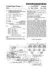
Turning now to FIG. 2, calibrated halftone output images
are created by computer front-ends in a page description
language 25 as shown. Language 25 is then sent to an
imagesetter comprised of a raster image processor, or a RIP,
26. RIP 26 then converts language 25 into a raster format
which is then sent to recorder 27 . Recorder 27 records the
BRIEF DESCRIPTION OF THE DRAWINGS
FIG. 1 is a plan view of a sample test strip pattern used
55
halftone input image on photographic media and delivers
that media to photoprocessor 28 for chemical processing and
development. Output from photoprocessor 28 is then char
by the present invention in setting the imagesetter exposure
intensity setting and generating halftone response function
the ?ow of data and steps used in the calibration process;
acterized in one of two categories, namely, uncalibrated
halftone output images 29 or calibrated halftone output
images 30. Uncalibrated output 29 is then used to charac
terize the halftone response of the imagesetter, ?lm and
photoprocessor system for different combinations of media,
resolution and halftone frequency 45, 46 and 47, respec
and,
tively.
for calibration set construction;
FIG. 2 is a diagrammatic block representation of the 60
present invention showing various components along with
FIG. 3 is a graph depicting the method by which, given a
calibration set selected for resolution, exposure intensity and
halftone screen frequency, the transfer function is derived
for the proper output sense condition.
Test pattern 10 shown in FIG. 1 can thereby be encoded
65
from page description language 25 to begin the calibration
process. Namely, description language of a halftone image
corresponding to test pattern 10 is sent via channel 31 to RIP
5,457,541
10
26. Test pattern 10 is then ultimately imaged at a predeter
mined media 45, resolution 46 and halftone frequency 47.
First, the gray values in test pattern 10 are mapped through
given calibration set 50 within RIP 26 to provide linearized,
calibrated halftone response output.
transfer function 33. Note that line art and text, through
black in a positive page image, is still considered a gray
33 is in place, subsequent halftone input images can then be
value of 100%, and is passed through transfer function 33.
function 33. Accordingly, at the start of processing any
subsequent halftone input image in the form of subsequent
page description language 32, selector 51 is called upon to
Once calibration sets 50 are obtained and transfer function
calibrated in accordance with calibration sets 50 and transfer
Not shown, and not germane to this discussion, are the
mechanisms that RIP 26 uses to generate the actual text in
line art images included in a complete page description.
select a corresponding calibration set 50 appropriate to the
current system conditions such as e.g., exposure intensity
For purpose of forming calibration sets and characterizing
the halftone response, transfer function 33 is set to the
21, media 45, resolution 46, screen frequency 47, etc.
Current media 45 is determined by a one-to-one mapping
process with the exposure intensity 54 which is determined
from recorder 27 by query. For example, all ?lm test strips
10 are exposed at the same exposure intensity setting 21 and
unitary function; that is the output gray value equals the
input value. Also possible, and equally usable, is an inverse
linear transfer function, in which the percent gray value is
subtracted from 100% to invert the image. The output value
equals 100% minus the input value. Unity or inverse transfer
function 33 is set at user direction through page description
all paper test strips are exposed at the same exposure
intensity setting 21. A requirement of the present invention
is that exposure intensity settings 21 be different for each
language 25.
different media 45 (paper or ?lm). In practice, this causes no
After transfer function 33 (which may have caused a
difficulty. In the event that two different media are properly
negative image), gray values 34 pass to halftone dot gen 20 exposed at the same exposure intensity setting 21, the
eration section 35. RIP 26 then creates a separate halftone
present invention requires that one media be shifted in
dot proportional in size, usually linear, to each gray value 34.
exposure intensity This shift is at most 0.4%, a negligible
Halftone dots representing each gray value 36 are placed in
amount. In this manner, selector 51 can determine which
raster memory 37. Raster memory 37 contains a pixel-by
group of calibration set is appropriate to the current media
pixel translation of page description 25. When page descrip
tion 25 has been completely processed, page image 38 is
25
Next, selector 51 narrows the list of possible sets by
examining the current resolution 53 from recorder 27. The
passed through a conditional invertor 39. Invertor 39 is
enabled to produce a negative at user direction through page
halftone parameters 55, notably halftone screen frequency,
description language 25.
After the pixel stream 40 leaves RIP 26, it enters recorder
27 and is passed through a similar conditional invertor 41.
This invertor 41 is also enabled under user direction through
45 by examining the exposure intensity setting only.
30
are determined either from default within RIP 26 or may be
overridden by page description language 25. Once media 45,
resolution 46 and screen frequency 47 are deterrrrined,
selector 51 examines the group of calibration sets 50 for a
page description language 25. From invertor 41, the pixel
match, and if a match is found, it presents the found
stream is used to modulate a light source scanning in raster
calibration set to the calibration function 52. In the event that
fashion 42 which then produces a photographic media of the 35 a calibration set match is not found, selector 51 presents a no
latent image corresponding to test pattern 10 representation
of the uncalibrated halftone input image.
set, which has the net effect of providing unadjusted half
tones. This method of operation has the advantage of not
disabling output in the event that halftone input images
The ?lm with the exposed test pattern 43 corresponding to
halftone input image test pattern 10, is then developed by
photoprocessor 28. Photoprocessor 28 has been used exten
sively in the art, and therefore, it is not discussed herein.
The processor 28 which produces uncalibrated test pattern
images 44 is activated for each combination of media,
resolution and halftone frequency desired, 45, 46 and 47,
respectively. Test pattern ?lms 43 are divided into a speci?c
media category 45 (?lm or paper), resolution 46 (high or
low) and halftone screen frequencies 47 (multiple lines per
inch). Note that while FIG. 2 shows two types of media 45,
40
could not be calibrated—a desirable outcome to many
operators. In another embodiment of the present invention,
selector 51 terminates current page description 25 if a
calibration set could not be found.
Note that in the current art, page description 25 may
45
specify any halftone screen frequency 47 from the practical
limits of 40 lines per inch to 300 lines per inch. It would be
unreasonable and unworkable to construct a calibration set
50 for every halftone frequency that could be speci?ed.
Evidence from testing has shown that a given calibration set
two resolution values 46 and three halftone screen frequen 50 at a given halftone screen frequency is accurate at a fre
quency signi?cantly different from that at which the set was
cies 47, it is clearly within the scope and spirit of this
measured. For instance, a calibration set measured at 150
invention to include multiple values beyond two types of
lines per inch may be accurate within a tolerance of 1% for
media, two resolution values and three halftone screen
ilS lines per inch. It is a feature of the present invention that
frequencies.
Upon obtaining media 45, resolution 46 and screen fre
quencies 47 of uncalibrated output 29, the operator can then
measure the test pattern gray scales 15 and 16 (shown in
55
which a calibration set may apply. Selector 51 matches the
current halftone frequency to a halftone range, consisting of
a starting frequency spanning to an ending frequency, inclu
FIG. 1) with a standard dot-area densitometer 48. The record
of these measurements, along with output sense (either
positive or negative), media, exposure intensity, resolution
the operator may specify a halftone frequency range for
60
sive. The halftone ranges for calibration set at a given
exposure intensity 21 and a given resolution 46 are not
allowed to overlap, thereby yielding the possibility of only
and halftone frequency constitute a calibration set 49. A
plurality of calibration sets 50 may be created, stored in RIP
26, and used with transfer function 33 to linearize the
one match. This method has the signi?cant advantage of not
allowing the operator to vary the number of calibration sets
imagesetter’s halftone response. One or more calibration
for various frequencies depending upon the operator’s accu
sets 49 are transferred to RIP 26 in a manner well known in 65
racy requirements.
the art. RIP 26 is constructed with a selector 51 and
calibration function 52. Thus, selector functions to select a
As gray values 32 are speci?ed in page description
language 25 where halftone input images are to be cali
5,457,541
11
12
brated, gray values are mapped through transfer function 33.
output sense conditions 56, 57 and 58. Calibration functions
52 is dependent on the individual output sense conditions.
Because the effect of the conditional pixel invertors 39 and
41 can be combined through the use of the “exclusive or”
function, there are four principal sense conditions to deal
Transfer function 33 is a convenient way to map user gray
values to values that are presented to dot generator 35 of RIP
26 so that the end result is a calibrated halftone output
image. Transfer function 33, however, has multiple uses.
Page description language 25 may specify an inverted
transfer function 33 in order to produce a negative image. In
this case, the invention concatenates calibration function 52
with the onetspeci?ed through page description language 25.
Care is taken to ensure that calibration function 52 is not
10
concatenated more than once.
The output sense can be provided by either the default
transfer function 33 or of one speci?ed via page description
56 provided to calibration function 52, along with the sense
of conditional RIP invertor 57, and the sense of conditional
The above four principal sense conditions are described
hereinbelow. In the case where Ntf is positive and invertors
are also positive, the dot area value from transfer function 33
is in positive dot, so it is ?rst converted to minus by
recorder invertor 58. These various data inputs provide the
present invention with bases for calibrating or mapping
subtracting from 100%. For an input value of 50%, calibra
tion function follows line 66 until in intersects curve 60 at
point 67. This occurs at a given percent dot area-to-com
within calibration function 52. Mapping or calibration
according to sense of conditional RIP invertor 39 and
conditional recorder invertor 41 is described with the aid of
FIG. 3.
Shown in FIG. 3 is a graphical depiction of the halftone
response contained in a typical calibration set. The ordinate
and abscissa are in % minus dot area, a typical and widely
mand point 68. The value to command from point 68 is then
subtracted from 100% and output along path 34 to dot
generator 35 of FIG. 2. Other transfer values are computed
used halftone measurement for negatives. Dot area measure 25
ments are usually spoken of in terms of printed dots on the
page. That is, a 10% dot area means that 10% of a given area
is covered by dots, or is mostly white. But for a negative that
would be used to produce-Fa printing plate that would make
with: 1) the transfer function 56 (Ntf) is positive, and
invertors 39 and 41 produce a positive for a positive image;
2) Ntf is negative and the invertors 39 and 41 produce a
positive for a negative image; 3) Ntf is positive and the
invertors 39 and 41 produce a negative for a negative image;
and 4) Ntf is negative and the invertors 39 and 41 produce
a negative for a positive image.
in like manner by intersecting curve 60. In the case where
Ntf is negative and invertors 39 and 41 are positive, the dot
area is used directly. For an input value of 50%, calibration
function 52 follows line 66 until in intersects curve 59 at
point 69. This occurs at a given percent dot area-to-com
mand point 70. The value to command from point 70 is then
used directly and output along path 34 to dot generator 35 of
FIG. 2. Note that the commanded values for 50% positive
a 10% dot area, the area is mostly black, or 90% of the area 30 and 50% negative are identical, and the commanded value
on the negative is covered by dots. For convenience, this
for 25% positive and 75% negative are identical. It is worth
area is called a 10% minus dot area, since the negative
produces a 10% dot.
Negative curve 59 of FIG. 3 results if the halftone
mentioning at this point that the use of two curves is not
mandatory. The mathematical relationship between positive
and negative dot area measurements is straight forward, but
measurement taken on gray scales 15 and 16 of FIG. 1 were 35 the use of two curves here is advantageous for recording the
taken from a negative; rather, they were minus dot measure
ments. If so, positive curve 60 can be constructed from curve
59. In the alternative, if halftone measurements taken on
gray scales 15 and 16 were taken from a positive, then they
are plotted on curve 60 and negative curve 59 is constructed
from positive curve 60. Curve 61 is the unity function, and
is shown for-reference.
Curve 60 is a complementary curve constructed from
curve 59in the following manner: for each % minus dot area
commanded, such as point 62, there is a corresponding point
63 for positive dots, which is simply expressed as 100% less
the minus dot point value. At point 62, the difference of the
commanded value to the actual value recorded, the distance
A, is transferred to the corresponding point 63, in opposite
halftone response measurement and to help understand the
operation of transfer function 33 and calibration of function
52. If Ntf is positive and invertors 39 and 41 are negative,
the dot area value from transfer function 33 is used directly.
40
For this case, however, calibration function 52 intersects the
positive curve 60 even though a negative image will ulti
mately be formed. From an input value of 90%, the curve is
intersected at point 71, for a commanded value at point 72.
The command value at point 72 is used directly and is sent
45
along path 34 to the dot generator 35. Still further, if Ntf is
negative and invertors 39 and 41 are negative, the dot area
value from transfer function 33 is inverted by subtracting
from 100%. For an input value of 90% this converts to 10%.
The calibration function intersects the negative curve 59,
even though a positive image will ultimately be formed.
From an input value of 10%, the curve is intersected at point
73. The value to command from point 73 is then subtracted
magnitude B equals B‘ for each corresponding point along
from 100% and is sent along path 34 to dot generator 35.
curve 61. At points 64 and 65, A equals A' equals B equals 55
Note that the last two examples shown above produce the
B‘.
same absolute gray value output. Again, the use of two
It is a feature of the present invention that the measure
curves is not mandatory but is helpful for explanation
ment points are symmetric about 50%. That is, a measure
purposes.
ment of 2% corresponds to a’ measurement of 98%, a 5% to
The invention herein described assumes short term sta
95%, a 7% to 93%, etc. While not mandatory for construc 60 bility in the photoprocessor 28, photographic media 43 and
tion of the complementary curve, this arrangement merely
photo exposure mechanism 42. Signi?cant effort within the
simpli?es the algorithms and assures accuracy.
current art is devoted to assuring the stability of these three
The purpose of the calibration function 52 is to invert the
items. In practice, the calibration sets 50, which are a
halftone response function from the selected calibration set
function of these three items, have been shown to be
50, depending upon the output sense conditions 56, 57 and 65 accurate for periods exceeding four weeks, provided there
58. The present invention relies on the fact that the measured
are good controls on the photographic processes. In the
halftone response is usable regardless of the state of the three
event of major change, such as a change in the type of ?lm,
sense, as the distance. A'. In like manner, point 63’s distance
to the negative curve B is transferred to point 62 in opposite
fashion as distance B‘. The magnitude of A equals A' and the
5,457,541
13
14
chemicals or processor, the existing calibration sets 50 may
said user controllable imaging parameters.
6. A method of calibrating output images from an image
need to be discarded and new ones created. The present
invention provides for easy veri?cation of the calibration set
accuracy and can be easily changed.
The current embodiment of the present invention also 5
assumes that dot generator 35 on FIG. 2, produces a ?xed
dent upon user controllable imaging parameters of said
determining a density of each image density of each input
image on said image bearing media for selected values
of said user controllable imaging parameters;
generating a plurality of calibration sets corresponding to
a variation between said requested image density and
the determined density for each said input image at
different values of said user controllable imaging
parameters; and
selector 51 with input from dot generator 35.
The foregoing description of the present invention has
been directed to particular preferred embodiments. It will be
apparent, however, to those skilled in the art that modi?ca
tions and changes in both apparatus and method may be
made without departing from the scope and spirit of the
20
automatically mapping said input images through a trans
fer function process capable of transferring either posi
tive or negative image densities of said input images to
either positive or negative image densities of said
output images.
7. A method of producing calibrated output images from
which can programmably receive calibration sets and apply
those calibrations sets to any form of input page description
an image generating device, comprising:
providing input images, each said image having a set of
language. Therefore, it is the applicant’s intention in the
following claims to cover all such equivalent modi?cations 25
and variations which fall within the true spirit and scope of
this invention.
What is claimed is:
1. A method of calibrating output images from an image
generating device, comprising the steps of:
providing input images, each including a plurality of
requested image densities, each said input image being
a function of user controllable imaging parameters that
35
determining a density of each said requested image den~
sity of each said input image on said image bearing
requested image density values, each image density
value being dependent upon selected controllable
imaging parameters;
reproducing said images onto image bearing media; deter
mining a density of each image density of each input
image on said image bearing media for selected values
of said selected controllable imaging parameters;
generating a plurality of calibration sets corresponding to
a variation between said requested image density and
the determined density for each said input image at
dilferent values of said selected controllable imaging
parameters;
mapping subsequent input images through a transfer
media;
function process to produce positive or negative sense
image density values for any subsequent input image;
generating a plurality of calibration sets in accordance
with said determining step, each said calibration set
corresponding to a variation between said requested
storing said calibration sets and said transfer function in
a local memory medium;
image density and said respective determined density
inputting said subsequent input images, each said subse
quent input image having a plurality of image densities;
for each said input image at different values of said user
controllable imaging parameters; and
image densities, wherein each image density is depen
reproducing said images onto image bearing media;
calibration sets 50 and the dot shape is taken into account by
affect image calibration;
reproducing said input images onto image bearing media;
providing input images, each having a set of requested
input image;
dot shape that varies only with gray value requested. In
another embodiment of the invention, the dot shape is
allowed to change. This replicates the groups 45, 46 and 47
for each different dot shape. Dot shape is also included in the
invention. For example, the present invention contemplates
functioning with any standard raster image processor for any
form of output media. Furthermore, the present invention
also contemplates use in any standard personal computer
generating device, comprising:
45
automatically converting a subsequent plurality of input
and
converting said image densities of each said subsequent
input image to respective image densities of said cali
brated output images according to programmed
images to a respective plurality of calibrated output
images according to changes made to said subsequent
input images by said calibration sets.
retrieval from said local memory medium of selected
stored calibration sets and said transfer function.
8. The method as recited in claim 7, wherein said con
2. The method as recited in claim 1, wherein said plurality
of calibrated output images each are a function of said user
controllable imaging parameters, and each of said plurality
of calibrated output images being programmable by at least
verting step further comprises applying said transfer func
tion to at least one image density of each said subsequent
input image to generate either positive or negative sense of
one of said calibration sets.
3. The method as recited in claim 1, wherein said auto 55 said calibrated output image.
matically converting step further comprises automatically
9. An apparatus for generating calibrated output images
from an image generating device, comprising:
converting either positive or negative sense uncalibrated
input images to negative sense calibrated output images.
a means for converting an input image into a page
4. The method as recited in claim 1, wherein said auto
description language, said input image being a function
matically converting step comprises automatically convert
of user controllable imaging parameters and including
ing either positive or negative sense uncalibrated input
images to positive sense calibrated output images.
a plurality of image density values, each said image
density value having a requested density value;
5. The method as recited in claim 1, wherein said step of
an image processor having a channel for receiving said
automatically converting further comprises programmably
selecting a particular calibration set of said plurality of
calibration sets to be used to convert one of said subsequent
plurality of input images depending upon current settings of
65
page description language and converting said lan
guage into a representation of said input image;
a recorder connected to said image processor, for record
5,457,541
15
16
ing said representation onto image bearing media;
mapping means for mapping either positive or negative
sense representations of said subsequent uncalibrated
an image density detector for measuring a density of each
said image density value of said recorded image on said
input images through said image processor, and said
image bearing media;
a computer for receiving a plurality of programmed
calibration sets, said sets including variations between
density measured by said image density detector and
corresponding requested density;
a selector accessed by said computer for receiving sub
sequent uncalibrated input images represented in said
page description language, and for automatically
selecting a corresponding calibration set stored in said
computer to programmably adjust said uncalibrated
input image to said calibrated output image; and
5
recorder, to be output as said calibrated output images
on said image bearing media.
10. The apparatus as recited in claim 9, wherein each said
calibration set comprises means for calibrating image den
sity values of said subsequent uncalibrated input images as
a function of said controllable imaging parameters.
11. The apparatus as recited in claim 9, wherein sai
image bearing media is paper.
'
12. The apparatus as recited in claim 9, wherein said
image bearing media is ?lm.