1
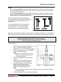
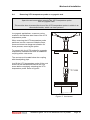
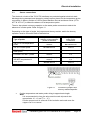
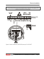
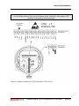
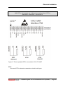
Electrical installation 3.3 Sensor connections The electronic circuits of the 762 VITO Interfaces are protected against electrical static discharge during transport and storage by metal jumpers placed on the temperature probe connectors. A dummy resistor of 10 is placed between the red and brown wires (VITOMTT & VITO-LT) to detect the absence of a temperature probe. There is also placed a dummy capacitor on the water probe connectors to detect the absence of a water probe. Refer to figure 11. Depending on the type of probe, the jumpers and dummy resistor and/or the dummy capacitor must be removed. Refer to table below. Type of probe 764/767 VITO temperature probe 765 VITO water probe Jumpers and dummy resistor on temperature probe connectors Dummy capacitor on water probe connectors remove do not remove do not remove remove 766/768 VITO temperature & water probe remove remove RTD/MRT/361 MPT probe remove n.a. front module (temp.): remove rear module (water): do not remove front module (temp.): n.a. rear module (water): remove 365 MPT temperature & water probe Figure 11 Location of jumpers and dummy resistor/capacitor Cut the temperature and water probe wiring to approximate length Note: It is recommended to loop the wires one time and strip each wire approximate 10 – 12 mm (6/16 – ½”). Use the proper tools for removal of the insulation and make sure the copper core is no carved. Installation guide 762 VITO interfaces & VITO probes Page 21