1
S/M No. : FR510P0010
Service Manual
Refrigerator
Model: FR-510M
FR-540M
FR-510P
FR-540P
✔ Caution
: In this Manual, some parts can be changed for improving, their
performance without notice in the parts list. So, if you need the
latest parts information,please refer to PPL(Parts Price List) in
Service Information Center (http://svc.dwe.co.kr).
DAEWOO ELECTRONICS CO., LTD.
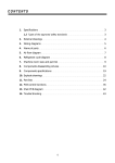
CONTENTS
1. Specification -----------------------------------------------------------------------------------------------1
2. External view-----------------------------------------------------------------------------------------------2
3. Wire diagram --------------------------------------------------------------------------------------------- 3
4. Name of parts--------------------------------------------------------------------------------------------- 4
5. Air flow diagram----------------------------------------------------------------------------------------- 5
6. Refrigerant cycle diagram ---------------------------------------------------------------------------- 6
7. Machine room view and part list--------------------------------------------------------------------7
8. Main components----------------------------------------------------------------------------------------- 8
9. Door color specification--------------------------------------------------------------------------------- 9
10. Exploded view and parts list ------------------------------------------------------------------------ 15
11. Electronic function -------------------------------------------------------------------------------------- 25
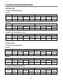
1. SPECIFICATION
MODEL NAME
Refirgerant
FR-510M
FR-540M
FR-510P
FR-540P
R12
200g
200g
200g
200g
R134a
170g
170g
170g
170g
Fan Cooling Convection
Cooling System
Refrigeration System
Air Forced Convection
Defrost System
Fin Evaporator Forced
Defrost Operation
Automatic Start & Stop
Cold Control
Freezer
Capacity
Refrigerator
Total
External
Dimension
Net Weight
299
418
Adjustable Dial
119
Adjustable Button
306
424
299
418
306
424
118
119
118
Height
1741mm
1768mm
1741mm
1768mm
Width
770mm
770mm
770mm
770mm
Depth
700mm
700mm
700mm
700mm
88Kg
89Kg
88Kg
89Kg
1
24
11
568
511
24
22
712
24
3
760
24
2
53
121
136
1039
988
770
1741
1422.5
11
60
595
568
511
24
31.5
22
760
770
770
53
1768
60
712
3
1066
1015
31.5
24
121
136
595
760
1422.5
760
770
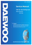
2. EXTERNAL VIEWS
1. FR-510M
700
2. FR-540M
700
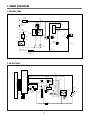
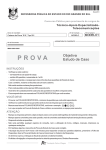
3. WIRE DIAGRAM
1. FR-510M, 540M
TEMP
FUSE
GRAY
BLACK
COMPRESSOR
OL
PTC
WHITE
BLUE
M
A
DOOR
SWITCH
DEFROST
HEATER
4
3
1
2
PINK
P-RELAY
WHITE
1
GN/YW
R-LAMP
RED
BIMETAL
L/BLUE
RED
PLUG
R-LAMP
2 BROWN
M
3
RED
4 RED
BROWN
F-LAMP
FM
BLACK
WHITE/BLUE
YELLOW
TEMP
CONTROLLER
2. FR-510P, 540P
M-PCB
YELLOW
YELLOW
GREEN
BROWN
WHITE
RED
WHITE
WHITE
RED
BLACK
VIOLET
F-PCB
BLACK
DOWN
TRANS
DEFROST
HEATER
GRAY
FM
TEMP
FUSE
R-LAMP
BLACK
BLUE
x2
F-SENSOR
D-SENSOR
ORANGE
x2
VIOLET
BROWN
BLUE
21 3 4
DOOR
SWITCH
BROWN
P-RELAY
GN/YW
BLUE
GRAYx2
WHITE F-LAMP
RED RED
YELLOW
YELLOW
BLACKx2
BLUEX3
PULG
R-LAMP
BLACK
BLUE
M A
BLACK
COMPRESSOR
BLACK
3
L/BLUE
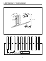
4. NAME OF PARTS
1. FR-510M, 540M
1
20
2
3
14
4
5
15
6
16
17
7
8
18
9
10
11
19
12
13
1 Freezer Compartment Lamp
2 Shelf Freezer & Ice Tray
Guide
3 Case Icing
4 Case Ice
5 Case Child
6 Temperature Controller
(Refrigerator Compartment)
7 Shelf Refrigerator
8 Window Refrigerator
9 Lever Moisture Control
10 Cover Vegetable
11 Case Vegetable
12 Front Grille
13 Adjustable Foot
14 Pocket Freezer
15 Egg Pocket
16 Case Egg
17 Pocket Multi
18 Pocket Bottle (A)
19 Pocket Bottle (B)
20 Freezer Temperature
Controller
(Freezer compartment)
2. FR-510P, 540P
1
2
3
14
4
5
15
6
16
17
7
8
18
9
10
11
19
12
13
4
1
2
3
4
5
6
7
8
9
10
11
12
13
14
15
16
17
18
19
20
Freezer Compartment lamp
Shelf Freezer & Ice Tray
Case Icing
Case Ice
Case Child
Temperature Controller
(Refrigerator Compartment)
Shelf Refrigerator
Window Refrigerator
Lever Moisture Controller
Cover Vegetable
Case Vegetable
Front Grille
Adjustable Foot
Pocket Freezer
Egg Pocket
Case Egg
Pocket Multi
Pocket Bottle (A)
Pocket Bottle (B)
Freezer Temperature
Controller
(Freezer Compartment)
24
3
1768
11
60
568
511
24 22
712
712
24
3
121
136
988
1039
770
1741
1422.5
11
60
595
568
511
24 22
31.5
760
4. FR-540P
760
24
5
700
770
700
53
770
53
1066
1015
31.5
24
121
136
595
760
1422.5
760
770
3. FR-510P
5. AIR FLOW DIAGRAM
Freezer door pocket
Do not put ice cream or frozen
food in freezer door pocket to
store for a long term. Opening
and shutting the door can rise up
the temperature.
-16~-18
-16~-18
-17~-19
Cold air absorbing duct
Do not place food in front
of the duct because it is the
entrance of the cold air.
2~4
Refrigerator door pocket
Temperature is high even if the
pocket is in the middle.
When storing margarine or cheese
for one or two weeks, make use
of the refrigerator shelf.
Crisper
Suitable in storing fruits or
vegetable.
Wrapping can prevent from
dryness.
3~5
3~5
A
2~4
1~3
2~4
1~3
2~4
C
2~3
Freezer room
Do not put any bottle such as
beer or beverage because it can
be frozen and broken.
Refrigerating room
This model is multi-flow type
which flows out cold air from
each shelf space. The hot air
after making the refrigerator
cold, flows into cooling system
through the front upper part.
B
5~7
6
Do not put food having much
moisture at the middle part of
each shelf space ("A", "B" and
"C" part). It can be frozen owing
to the low temperature.
6. REFRIGERANT CYCLE DIAGRAM
PIPE
HOT
ACCUM
AUX-HOT PIPE
BACK PLATE PIPE
MAIN CAPI TUB.
OSS
FIN CR
EVA
IPE
OT P
H
X
AU
SUC-PIPE
ER
DRY
COMP
C
O
M
P
R
E
S
S
O
R
A
U
X
I
C
O
N
P
I
P
E
H
O
T
P
I
P
E
A
U
X
I
H
O
T
P
I
P
E
B
A
C
K
D
R
Y
E
R
P
L
A
T
E
C
A
P
I
T
U
B
E
P
I
P
E
COOLING PIPE
7
E
V
A
P
O
R
A
T
O
R
A
C
C
U
M
U
L
A
T
O
R
S
U
C
P
I
P
E
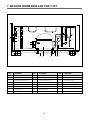
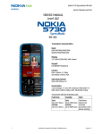
7. MACHINE ROOM VIEW AND PART LIST
11
19
16
7
13
21
20
17
8
15
18
12
6
9
5
22
1
NO
PART NAME
NO
2
3
4
10
14
PART NAME
NO
PART NAME
1
BASE COMPRESSOR
9
DRYER
17
BIND WIRE
2
COMPRESSOR
10
PIPE CON (SUC)
18
PLUG POWER AS
3
ABSORBER COMPRESSOR
11
VIBRATIONPROOF GUM
19
SCREW MACHINE
4
WASHER COMP. *T
12
PIPE CON (AUX)
20
PIPE CON (HOT)
5
SWITCH P-RELAY AS
13
HOSE DRAIN (B)
21
TAPE OPP
6
BAND RELAY
14
VIBRATIONPROOF MASS
22
PIPE CON (P.A)
7
TAPE COTTON
15
SCREW TAPPING
8
PIPE SERVICE
16
COVER CONNECTOR
8
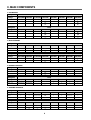
8. MAIN COMPONENTS
1. COMPRESSOR
Refrigerant
Voltage
R12
100V/50,60Hz 110V/60Hz
115, 120V/60Hz
127V/60Hz
220V/50Hz
220V/60Hz
230V/50Hz
PL25YE-4-C
SL28YE-5-C
Comp. model
X
X
BL25YE-2-C
SL28YE-5-C
Part code
X
X
3952125C20
3954128C50 3956125C40 3954128C50
Strating type
X
X
CSR
Refrigerant
Voltage
RSIR
RSCR
RSIR
220V/50Hz
220V/60Hz
230V/50Hz
R134a
100V/50,60Hz 110V/60Hz
115, 120V/60Hz
127V/60Hz
Comp. model
HBL25YE-C
HBL25YE-3-C HBL25YE-2-C
HSL27YE-5-C
X
HSL27YE-5-C
Part code
3952125L00
3952125L30
3952125L20
3954127L50
X
3954127L50
CSR
CSR
CSR
RSIR
X
RSIR
220V/50Hz
220V/60Hz
230V/50Hz
Strating type
240V/50Hz
240V/50Hz
2. RELAY ASSEMBLY
Refrigerant
Voltage
R12
100V/50,60Hz 110V/60Hz
115, 120V/60Hz
127V/60Hz
240V/50Hz
Relay model
X
X
317THBYY-52
276THBYY-52 197SHBYY-52 276THBYY-52
Part code
X
X
3018112000
3018105641 3018104102 3018105641 3018105641
Refrigerant
R134a
Voltage
100V/50,60Hz 110V/60Hz
Relay model
Part code
115, 120V/60Hz
127V/60Hz
220V/50Hz
220V/60Hz
230V/50Hz
240V/50Hz
801RFBZZ-52 445RHBZZ-52 317THBYY-52
276THBYY-52
X
276THBYY-52
3018101630 3018101620 3018112000
3018105641
X
3018109901 3018105641
3. RUNNING CAPACITOR
Refrigerant
Voltage
Spec.
Part code
Refrigerant
Voltage
Spec.
Part code
115, 120V/60Hz
300V/7µF
3816800400
R12
127V/60Hz 220V/50Hz
X
X
220V/60Hz
350V/5µF
400EL15110
230V/50Hz
X
X
240V/50Hz
X
X
100V/50,60Hz 110V/60Hz 115, 120V/60Hz
200V/12µF
300V/7µF
3816801910 3816800400
R134a
127V/60Hz 220V/50Hz
X
X
220V/60Hz
X
X
230V/50Hz
X
X
240V/50Hz
X
X
220V/50Hz
220V/60Hz
230V/50Hz
240V/50Hz
100V/50,60Hz 110V/60Hz
X
X
X
X
4. STARTING CAPACITOR
Refrigerant
Voltage
R12
100V/50,60Hz 110V/60Hz
115, 120V/60Hz
127V/60Hz
Spec.
X
X
200V/100µF
X
X
290V/50 µF
X
Part code
X
X
401RD35050
X
X
4124G62020
X
220V/50Hz
220V/60Hz
230V/50Hz
240V/50Hz
200V/100µF
X
X
290V/50 µF
X
401RD35050
X
X
4124G62020
X
Refrigerant
Voltage
Spec.
Part code
R134a
100V/50,60Hz 110V/60Hz
115, 120V/60Hz
127V/60Hz
9
5. F-FAN MOTOR
Refrigerant
Voltage
R12, R134a
100V/50,60Hz 110V/60Hz
115, 120V/60Hz
127V/60Hz
220V/50Hz
220V/60Hz
230V/50Hz
Spec.
3211DWBFH
3211DWBFI
3211DWBFL
Part code
3011800660
3011800670
3011800640
240V/50Hz
6. DEFROST HEATER
Refrigerant
Voltage
Spec.
Part code
R12, R134a
100V/50,60Hz 110V/60Hz
115, 120V/60Hz
127V/60Hz
220V/50Hz
148W
148W
3012801300
3012801000
220V/60Hz
230V/50Hz
240V/50Hz
220V/60Hz
230V/50Hz
240V/50Hz
220V/60Hz
230V/50Hz
240V/50Hz
220V/60Hz
230V/50Hz
240V/50Hz
5EPK057020
5EPK057608
230V/50Hz
240V/50Hz
7. LAMP ASSEMBLY
Refrigerant
Voltage
Spec.
Part code
R12, R134a
110V/50,60Hz 110V/60Hz
115, 120V/60Hz
127V/60Hz
220V/50Hz
15W
15W
3013600050
3013600020
8. DEFROST TIMER (FR-510M, 540M)
Refrigerant
Voltage
R12, R134a
100V/50,60Hz 110V/60Hz
115, 120V/60Hz
127V/60Hz
Spec.
Part code
220V/50Hz
TMDEX09UM1
3010513900
3018103920
9. PCB TRANSFORMER (FR-510P, 540P)
Refrigerant
Voltage
Part code
R12, R134a
100V/50,60Hz 110V/60Hz
115, 120V/60Hz
127V/60Hz
5EPK057605
220V/50Hz
5EPK057604
10. MAIN PCB ASSEMBLY (FR-510P, 540P)
Refrigerant
Voltage
Spec.
Part code
R12, R134a
100V/50,60Hz 110V/60Hz
115, 120V/60Hz
127V/60Hz
220V/50Hz
220V/60Hz
P707
3014304010
3014303810
11. DRYER
Refrigerant
R12
R134a
Spec.
10 g
15 g
3016800103
3016800910
Part code
10
POWER CORD SPECIFICATION
NO
SHAPE OF POWER CODE
PART CODE
DESCRIPTION
1
3011315000
CP-2PIN
FOR EUROPEAN COUNTRY
2
401RA17200
CP-2PIN
FOR OTHER COUNTRY
3
4006D17101
KP-30
FOR AMERICA
4
401PD17101
KP-211
FOR JAPAN & TAIWAN
5
3011300801
BP-3PIN
6
3011303010
#267
7
3011315310
8
3011303050
BS-1363A
FOR U.K, MIDDLE ASIA
SINGAPORE & MALAYSIA
9
3011301200
KP-551/550
FOR CHINA & AUSTRALIA
FOR CHILE
FOR ISRAEL
* Upper power cord’s part code is only for lead wire, without any kinds of terminal or housing.
11
REMARK
9. DOOR COLOR SPECIFICATION
1. FR-510M, 510P
1. ASSEMBLY URETHAN FREEZER DOOR
1) FR-510M
Refrigerant
Color type
Part code
R12
Dull lamina
High glossy
sheet
lamina sheet
X
X
R134a
Normal PCM
X
High glossy
Dull lamina
High glossy
bright PCM
sheet
lamina sheet
PFDT1UH110
X
X
Normal PCM
X
High glossy
bright PCM
PFDT1UH115
2) FR-510P
Refrigerant
Color type
Part code
R12
Dull lamina
High glossy
sheet
lamina sheet
X
X
R134a
Normal PCM
X
High glossy
Dull lamina
High glossy
bright PCM
sheet
lamina sheet
PFDT1UH030
X
X
Normal PCM
X
High glossy
bright PCM
PFDT1UH035
2. ASSEMBLY URETHAN REFRIGERATOR DOOR
Refrigerant
Color type
Part code
R12
Dull lamina
High glossy
sheet
lamina sheet
X
X
R134a
Normal PCM
X
High glossy
Dull lamina
High glossy
bright PCM
sheet
lamina sheet
PFDU2UH030
X
X
Normal PCM
X
High glossy
bright PCM
PFDU2UH035
2. FR-540M, 540P
1. ASSEMBLY URETHAN FREEZER DOOR
1) FR-540M
Refrigerant
Color type
Part code
R12
Dull lamina
High glossy
sheet
lamina sheet
X
X
R134a
Normal PCM
X
High glossy
Dull lamina
High glossy
bright PCM
sheet
lamina sheet
PFDT1UJ130
X
X
Normal PCM
X
High glossy
bright PCM
PFDT1UJ135
2) FR-540P
Refrigerant
Color type
Part code
R12
Dull lamina
High glossy
sheet
lamina sheet
X
X
R134a
Normal PCM
X
High glossy
Dull lamina
High glossy
bright PCM
sheet
lamina sheet
PFDT1UJ030
X
X
Normal PCM
X
High glossy
bright PCM
PFDT1UJ035
2. ASSEMBLY URETHAN REFRIGERATOR DOOR
Refrigerant
Color type
Part code
R12
Dull lamina
High glossy
sheet
lamina sheet
X
X
R134a
Normal PCM
X
High glossy
Dull lamina
High glossy
bright PCM
sheet
lamina sheet
PFDU2UJ030
X
X
12
Normal PCM
X
High glossy
bright PCM
PFDU2UJ035
COLOR TABLE
1. PCM type
NO
COLOR CHIP
COLOR NAME
1
P/WITH (WH069)
2
'94 L/GRAY (GY158)
3
'95 L/GRAY (GY259)
4
'94 M/GRAY (GY331)
5
'95 M/GRAY (GY335)
6
'97 M/GRAY (GY267)
7
M. D/GRAY (GY750)
8
N/BLUE (BL718)
9
MINT GREEN (GN206)
10
'97 BEIGE (BE215)
13
2. Lamina sheet type
NO
COLOR CHIP
COLOR NAME
1
P/WITH (WH069)
2
'94 L/GRAY (GY158)
3
'95 L/GRAY (GY259)
4
'94 M/GRAY (GY331)
5
'95 M/GRAY (GY335)
6
'97 M/GRAY (GY267)
7
M. D/GRAY (GY750)
8
N/BLUE (BL718)
9
MINT GREEN (GN206)
10
S/GOLD
11
G/GREEN
14
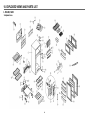
10. EXPLODED VIEWS AND PARTS LIST
1. FR-510M, 540M
1.Exploded view
15
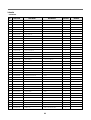
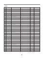
2. Parts list
CONTENTS
NO
PART CODE
PART NAME
DESCRIPTION
QUANTITY
1
ASSY URT CAB
1
2
HEATER GLAS TUBE AS
1
3
3011408100
COVER HTR *U
1
4
3011408200
COVER HTR *T
1
5
4010G19010
FIXTURE DEFR HTR
2
6
3017000502
EVAPORATOR SAS
1
7
400EL21213
FUSE TEMP AS
1
8
3018111100
SWITCH BIMTL AS
1
9
3014502101
PLATE DV AS
1
10
3018100010
SWITCH DR
11
4010G30351
FIXTURE DR CHILD
2
12
3010302512
BASE COMP SAS
1
13
3010100201
ABSORBER COMP
14
3014502304
PLATE AXCON AS
1
COMPRESSOR
1
15
16
4019H09030
17
WASHER COMP *T
DSD-5
NR H=40
SK-5
SWITCH P RELAY AS
4
3816100100
RELAY BAND
19
3010604802
BRACKET ADJ FT *L AS
1
20
3010604902
BRACKET ADJ FT *R AS
1
21
3016000220
SPECIAL SCREW
2
22
3012900620
HINGE *M AS
23
MOTOR AS
1
1
3018103920
SWITCH D TIMER AS
CHILE 350
1
25
3011406600
COVER F M/F DUCT A
ABS
1
LAMP AS
3
G.E, PC-121R
REFER TO # 9
1
24
26
REFER TO # 9
4
18
D/C
REFER TO # 10
1
1
SK-5 0.7T ZN-3-A
REMARK
27
3015500400
WINDOW F
28
3010008910
ASSY M/F DUCT
29
3013304901
INSULATOR M/F DUCT
F-PS
1
30
4010G26030
INSULATOR DAMP B
F-PS
1
31
4010G26401
R DAMPER AS
HF380
1
32
4017G31152
KNOB DAMP
ABS
1
33
3011408803
COVER M/F DUCT
HIPS
1
34
3015500703
WINDOW R
GPPS
1
35
3017900802
SOCKET F LAMP AS
36
3011408400
COVER M/PCB BOX
REFER TO # 10
REFER TO # 10
1
1
1
PP
1
37
DRYER AS
1
REFER TO # 10
38
ASSY URT *T DOOR
1
REFER TO # 12
39
3017402202
LINER F DR
ABS 1.4 x 785 x 1140
16
1
NO
PART CODE
40
3012300600
GASKET F DR AS
PVC-S
1
41
3019002100
POCKET F *T
GPPS T3.0
2
42
3014202610
PANEL F CONTL
ABS T2.3
1
43
3012901400
HINGE *T AS
44
3016001800
SPECIAL BOLT
M6 x L16
4
45
3011408700
COVER *T HI
PP
1
46
PART NAME
DESCRIPTION
QUANTITY
1
ASSY URT *U DOOR
1
47
3017402301
LINER R DR
ABS 1.4 x 785 x 1060
1
48
3012301600
GASKET R DR AS
PVC-S+MAGNET
1
49
3012900401
HINGE *U AS
MF-ZN5-C
1
50
3016000800
SPECIAL SCREW
T1 TRS 4 x 12 PW
4
51
7400108511
WASHER PLAIN
PW-1.5T 8.5/20 MFZN
1
52
REMARK
CORD POWER AS
1
1
53
3010501601
BOX CONTL AS
54
3010500403
BOX CONTL
55
3018300401
THERMOSTAT
56
4017G31041
KNOB C/S
57
3013300022
INSULATOR F LUVR AS
1
58
3018900900
LOUVER F M/F AS
1
59
3011409010
COVER VEGETB BOOX AS
CV+F+KNOB+NAMP
1
60
3010503720
CASE VEGTB
GPPS T 3.0
1
61
3011102300
CASE CHILD
GPPS T 3.5
1
62
3019002000
POCKET MULT
GPPS T 3.0
2
63
3019002600
POCKET BOTL B
GPPS T 3.0
1
64
3011705620
DOOR CHILD
GPPS
1
65
3011103900
CASE EGG
GP
2
66
4010E99102
BOX ICE AS
67
4010G30661
BOILD
PP T1.3
1
68
3017801920
SHELF R
GPPS
2
69
3017804700
SHELF F
70
3012500510
GUIDE ICING CASE
GPPS
1
71
3011408501
COVER CAB BRKT
ABS
1
72
3011102100
CASE ICING
PP
2
73
3012400502
GRILLE
PP
1
74
3010010900
ASSY ADJ FT PAKG
HIPS
1
1
ABS
1
1
1
1
17
REFER TO # 12
REFER TO # 11
FR-540M
NO
PART CODE
PART NAME
DESCRIPTION
QUANTITY
1
ASSY URT CAB
1
2
HEATER GLAS TUBE AS
1
3
3011408100
COVER HTR *U
AL
1
4
3011408200
COVER HTR *T
AL
1
5
4010G19010
FIXTURE DEFR HTR
2
6
3017000502
EVAPORATOR SAS
1
7
400EL21213
FUSE TEMP AS
1
8
3018111100
SWITCH BIMTL AS
1
9
3014502101
PLATE DV AS
1
10
3018100010
SWITCH DR
1
11
4010G30351
FIXTURE DR CHILD
2
12
3010302512
BASE COMP SAS
1
13
3010100201
ABSORBER COMP
14
3014502304
PLATE AXCON AS
1
COMPRESSOR
1
15
16
4019H09030
17
WASHER COMP *T
NR H=40
SK-5
SWITCH P RELAY AS
3816100100
RELAY BAND
19
3010604802
BRACKET ADJ FT *L AS
1
20
3010604902
BRACKET ADJ FT *R AS
1
21
3016000220
SPECIAL SCREW
M6 x 16 SWCH22A
2
22
3012900620
HINGE *M AS
D/C
1
MOTOR AS
1
3018103920
SWITCH D TIMER AS
CHILE 350
1
25
3011406600
COVER F M/F DUCT A
ABS
1
LAMP AS
3
G.E, PC-121R
REFER TO # 9
1
24
26
REFER TO # 9
4
18
23
REFER TO # 10
4
1
SK-5 0.7T ZN-3-A
REMARK
27
3015500400
WINDOW F
28
3010008910
ASSY M/F DUCT
29
3013304901
INSULATOR M/F DUCT
F-PS
1
30
4010G26030
INSULATOR DAMP B
F-PS
1
31
4010G26401
R DAMPER AS
HF380
1
32
4017G31152
KNOB DAMP
ABS
1
33
3011408803
COVER M/F DUCT
HIPS
1
34
3015500703
WINDOW R
GPPS
1
35
3017900802
SOCKET F LAMP AS
36
3011408400
COVER M/PCB BOX
REFER TO # 10
REFER TO # 10
1
1
1
PP
1
37
DRYER AS
1
REFER TO # 10
38
ASSY URT *T DOOR
1
REFER TO # 12
39
3017402202
LINER F DR
ABS 1.4 x 785 x 1140
18
1
NO
PART CODE
40
3012300600
GASKET F DR AS
PVC-S
1
41
3019002100
POCKET F *T
GPPS T3.0
2
42
3014202610
PANEL F CONTL
ABS T2.3
1
43
3012901400
HINGE *T AS
44
3016001800
SPECIAL BOLT
M6¡¿L16
4
45
3011408700
COVER *T HI
PP
1
46
PART NAME
DESCRIPTION
QUANTITY
1
ASSY URT *U DOOR
1
47
3017402501
LINER R DR
ABS 1.4 x 785 x 1085
1
48
3012300500
GASKET R DR AS
PVC-S
1
49
3012900401
HINGE *U AS
MF-ZN5-C
1
50
3016000800
SPECIAL SCREW
T1 TRS 4 x 12 PW
4
51
7400108511
WASHER PLAIN
PW-1.5T 8.5/20 MFZN
1
52
REMARK
CORD POWER AS
1
1
53
3010501601
BOX CONTL AS
54
3010500403
BOX CONTL
55
3018300401
THERMOSTAT
56
4017G31041
KNOB C/S
57
3013300022
INSULATOR F LUVR AS
1
58
3018900900
LOUVER F M/F AS
1
59
3011409010
COVER VEGETB BOOX AS
CV+F+KNOB+NAMP
1
60
3010503720
CASE VEGTB
GPPS T 3.0
1
61
3011102300
CASE CHILD
GPPS T 3.5
1
62
3019002000
POCKET MULT
GPPS T 3.0
2
63
3019002600
POCKET BOTL B
GPPS T 3.0
1
64
3011705620
DOOR CHILD
GPPS
1
65
3011103900
CASE EGG
GP
2
66
4010E99102
BOX ICE AS
SAN+ABS
1
67
4010G30661
BOILD
PP T1.3
1
68
3017801920
SHELF R
GPPS
2
69
3017804700
SHELF F
GPPS
1
70
3012500510
GUIDE ICING CASE
GPPS
1
71
3011408501
COVER CAB BRKT
ABS
1
72
3011102100
CASE ICING
PP
2
73
3012400502
GRILLE
PP
1
74
3010010900
ASSY ADJ FT PAKG
HIPS
1
1
ABS
1
1
19
REFER TO # 12
REFER TO # 11
2. FR-510P, 540P
1. Exploded view
20
2. Parts list
FR-510P
✔ Caution : In this Service Manual, some parts can be changed for improving, their performance without notice in the parts list.
So, if you need the latest parts information, please refer to PPL (Parts Price List) in Service Information Center
(http://svc.dwe.co.kr)
NO
PART CODE
PART NAME
DESCRIPTION
QUANTITY
1
ASSY URT CAB
1
2
HEATER GLAS TUBE AS
1
REMARK
REFER TO # 10
3
3011408100
COVER HTR *U
AL
1
4
3011408200
COVER HTR *T
AL
1
5
4010G19010
FIXTURE DEFR HTR
2
6
3017000502
EVAPORATOR SAS
1
7
400EL21213
FUSE TEMP AS
1
8
400EL30151
SENSOR F-D AS
1
9
3018100010
SWITCH DR
10
3010302512
BASE COMP SAS
11
3010100201
ABSORBER COMP
12
3014502304
PLATE AXCON AS
1
13
COMPRESSOR
1
REFER TO # 9
14
SWITCH P RELAY AS
1
REFER TO # 9
DSD-5
1
1
NR H=40
15
3816100100
RELAY BAND
16
3010604802
BRACKET ADJ FT *L AS
1
17
3010604902
BRACKET ADJ FT *R AS
1
PCB MAIN AS
1
18
SK-5 0.7T ZN-3-A
4
1
19
3016000220
SPECIAL SCREW
M6 x 16 SWCH22A
2
20
3012900620
HINGE *M AS
D/C
1
21
MOTOR AS
1
22
3011406600
COVER F M/F DUCT A
23
3017900802
SOCKET F LAMP AS
1
LAMP AS
3
24
ABS
G.E, PC-121R
REFER TO # 10
REFER TO # 10
1
REFER TO # 10
25
3015500400
WINDOW F
1
26
3010008910
ASSY M/F DUCT
27
3013304901
INSULATOR M/F DUCT
F-PS
1
28
4010G26030
INSULATOR DAMP B
F-PS
1
29
4010G26401
R DAMPER AS
HF 380
1
30
4017G31152
KNOB DAMP
ABS
1
31
3011408803
COVER M/F DUCT
HIPS
1
32
3015500703
WINDOW R
GPPS
1
33
3011410000
COVER M/PCB BOX AS
1
34
DRYER AS
1
REFER TO # 10
35
ASSY URT *T DOOR
1
REFER TO # 12
1
36
3017402202
LINER F DR
ABS
1
37
3012301500
GASKET F DR
PVC-S+MAGNET
1
38
3019002100
POCEKT F *T
GPPS T3.0
2
39
3014201300
PANEL F CONTL
ABS
1
21
NO
PART CODE
40
3014302300
PCB *F AS
1
41
3012901400
HINGE *T AS
1
42
3016001800
SPECIAL BOLT
M6 x L16
4
43
3011408700
COVER *T HI
PP
1
44
PART NAME
DESCRIPTION
ASSY URT *U DOOR
QUANTITY
1
45
3017402301
LINER R DR
ABS 1.4 x 785 x 1060
1
46
3012301600
GASKET R DR AS
PVC-S+MAGNET
1
47
3012900401
HINGE *U AS
MF-ZN5-C
1
48
3016000800
SPECIAL SCREW
T1 TRS 4 x 12 PW
4
REMARK
REFER TO # 12
49
CORD POWER AS
1
REFER TO # 11
50
POWER TRANS
1
REFER TO # 10
51
3013300022
INSULATOR F LUVR AS
B-4231M
1
52
4017Z29010
BRACKET F SENS
SPCC
1
53
3018900900
LOUVER F M/F AS
54
3011409010
COVER VEGETB BOX AS
CV+F+KNOB+NAMP
1
55
3010503720
CASE VEGTB
GPPS T3.0
1
56
3011102300
CASE CHILD
GPPS T3.5
1
57
3019002000
POCKET MULT
GPPS T3.0
1
58
3019002600
POCKET BOTL B
GPPS T3.0
1
59
3011705620
DOOR CHILD
GPPS
1
60
3019004100
POCKET *A
GPPS
2
61
3011103900
CASE EGG
GP
2
62
4010E99102
BOX ICE AS
SAN+ABS
1
63
4010G30661
BOILD
PP T1.3
1
64
3017801920
SHELF R
GPPS
2
65
3017804700
SHELF F
GPPS
1
66
3012500510
GUIDE ICING CASE
GPPS
1
67
3011408501
COVER CAB BRKT
ABS
1
68
3011102100
CASE ICING
PP
2
69
3012400502
GRILLE
PP
1
70
3010010900
ASSY ADJ FT PAKG
1
1
22
FR-540P
✔ Caution : In this Service Manual, some parts can be changed for improving, their performance without notice in the parts list.
So, if you need the latest parts information, please refer to PPL (Parts Price List) in Service Information Center
(http://svc.dwe.co.kr)
NO
PART CODE
PART NAME
DESCRIPTION
QUANTITY
1
ASSY URT CAB
1
2
HEATER GLAS TUBE AS
1
REMARK
REFER TO # 10
3
3011408100
COVER HTR *U
AL
1
4
3011408200
COVER HTR *T
AL
1
5
4010G19010
FIXTURE DEFR HTR
2
6
3017000502
EVAPORATOR SAS
1
7
400EL21213
FUSE TEMP AS
1
8
400EL30151
SENSOR F-D AS
1
9
3018100010
SWITCH DR
10
3010302512
BASE COMP SAS
11
3010100201
ABSORBER COMP
12
3014502304
PLATE AXCON AS
1
13
COMPRESSOR
1
REFER TO # 9
14
SWITCH P RELAY AS
1
REFER TO # 9
DSD-5
1
1
NR H=40
15
3816100100
RELAY BAND
16
3010604802
BRACKET ADJ FT *L AS
1
17
3010604902
BRACKET ADJ FT *R AS
1
PCB MAIN AS
1
18
SK-5 0.7T ZN-3-A
4
1
19
3016000220
SPECIAL SCREW
M6 x 16 SWCH22A
2
20
3012900620
HINGE *M AS
D/C
1
21
MOTOR AS
1
22
3011406600
COVER F M/F DUCT A
23
3017900802
SOCKET F LAMP AS
1
LAMP AS
3
24
ABS
G.E, PC-121R
REFER TO # 10
REFER TO # 10
1
REFER TO # 10
25
3015500400
WINDOW F
1
26
3010008910
ASSY M/F DUCT
27
3013304901
INSULATOR M/F DUCT
F-PS
1
28
4010G26030
INSULATOR DAMP B
F-PS
1
29
4010G26401
R DAMPER AS
HF380
1
30
4017G31152
KNOB DAMP
ABS
1
31
3011408803
COVER M/F DUCT
HIPS
1
32
3015500703
WINDOW R
GPPS
1
33
3011410000
COVER M/PCB BOX AS
1
34
DRYER AS
1
REFER TO # 10
35
ASSY URT *T DOOR
1
REFER TO # 12
1
36
3017402202
LINER F DR
ABS 1.4 x 785 x 1140
1
37
3012301500
GASKET F DR
PVC-S+MAGNET
1
38
3019002100
POCKET F *T
GPPS T3.0
2
39
3014201300
PANEL F CONTL
ABS
1
23
NO
PART CODE
40
3014302300
PCB *F AS
1
41
3012901400
HINGE *T AS
1
42
3016001800
SPECIAL BOLT
M6 x L16
4
43
3011408700
COVER *T HI
PP
1
44
PART NAME
DESCRIPTION
ASSY URT *U DOOR
QUANTITY
1
45
3017402501
LINER R DR
ABS 1.4 x 785 x 1085
1
46
3012300500
GASKET R DR AS
PVC-S
1
47
3012900401
HINGE *U AS
MF-ZN5-C
1
48
3016000800
SPECIAL SCREW
T1 TRS 4¡¿12 PW
4
REMARK
REFER TO # 12
49
CORD POWER AS
1
REFER TO # 11
50
POWER TRANS
1
REFER TO # 10
1
51
3013300022
INSULATOR F LUVR AS
52
4017Z29010
BRACKET F SENS
53
3018900900
LOUVER F M/F AS
54
3011409010
COVER VEGETB BOOX AS
CV+F+KNOB+NAMP
1
55
3010503720
CASE VEGTB
GPPS T3.0
1
56
3011102300
CASE CHILD
GPPS T3.5
1
57
3019002000
POCEKT MULT
GPPS T3.0
1
58
3019002600
POCEKT BOLT B
GPPS T3.0
1
59
3011705620
DOOR CHILD
GPPS
1
60
3019004100
POCKET *A
GPPS
2
61
3011103900
CASE EGG
GP
2
62
4010E99102
BOX ICE AS
SAN+ABS
1
63
4010G30661
BOILD
PP T1.3
1
64
3017801920
SHELF R
GPPS
2
65
3017804700
SHELF F
GPPS
1
66
3012500510
GUIDE ICING CASE
GPPS
1
67
3011408501
COVER CAB BRKT
ABS
1
68
3011102100
CASE ICING
PP
2
69
3012400502
GRILLE
PP
1
70
3010010900
ASSY ADJ FT PAKG
SPCC
1
1
1
24
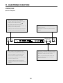
11. ELECTRONIC FUNCTION
1. FR-510P, 540P
1) How to use the panel
• When you press the Time Set button,
"HOUR" blinks, and the time can be set by
pressing the time adjust button( , ).
• By pressing time set button again,
"MINUTE" blinks and the time can be set, by
pressing the time adjust Button.
• Pressing the economic freezing button to
start the function.
• Pressing the time set button again stops the
blinking and clock will begin the operation.
• Press again to revert to the previous temp.
setting.
QUICK
FREEZING
TIME SET
FRZ.
W
N
C
QF
• Quick freeze function operates for 150
minutes to quickly freeze food or make ice.
AM
FM
FRESH
CLEAN
FREEZER TEMP. CONTROL
TIME ADJUSTER
ECONOMIC
FREEZING
• By pressing the Freezer Compartment Temp.
adjust button, you can set the temp; warm,
mid warm, normal, mid-cold or cold.
• The Clock displays "150 minutes" for 8
seconds and then displays time again.
• When you press the time set button and
then the time adjust button HOUR and
MINUTE can be set.
• Press the button again in 8 seconds to stop
the quick freeze function.
• Pressing the button while it shows time,
displays a remaining quick freeze time for 8
seconds.
25
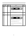
2) Function table
NO.
1
Control
Function
Initial
operation
Control
Objects
Time
Temperature
control
Contents
Remark
1. In the initial operation, the temperature is automatically set at
normal position and the clock is set at 12:00 AM.
QUICK
FREEZING
TIME SET
AM
W
FRZ.
2
Clock
function
LED
TIME SET
W
FRZ.
Quick
freezing
COMP.
F-fan
C-fan
LED
FREEZER TEMP. CONTROL
TIME ADJUSTER
ECONOMIC
FREEZING
1. The time is set at 12:00 AM in initial operation.
2. Time setting (Setting time 1:05 AM)
1) When the time set button is pressed, the hour(12) blinks in
5 sec. interval.
2) Set hour with the time adjust button( , ).
3) When press the time set button again, hour is set and
minute(00) will blink.
4) Set minute with the time adjust button( , ).
5) If press the time set button again, time will be set.
ç If do not set time in 5 seconds after pressing the time
adjust button, the function will be canceled automatically.
QUICK
FREEZING
3
FRESH
CLEAN
N
C
QF
AM
FRESH
CLEAN
FREEZER TEMP. CONTROL
TIME ADJUSTER
ECONOMIC
FREEZING
1. When press the quick freezing button at 1:05 AM, quick
freezing time of 150 min. will display for 8 sec., and then
return to 1:05 AM.
ç Pressing the button again in 8 sec. will cancel the function.
QUICK
FREEZING
TIME SET
QF
FRZ.
AM
FRESH
CLEAN
FREEZER TEMP. CONTROL
TIME ADJUSTER
ECONOMIC
FREEZING
2. The bar LED lights 3 times every 30 min. in a row.
ç The LED displays the irrelevant temperature.
Quick Freeze
is on
C
Q.F
After
30 minutes
C
Q.F
After
an Hour
C
Q.F
3. The COMP. and F-fan is operated 150 min. jointly.
4. If press the quick freezing button in quick freezing mode, the
LED displays remaining time.
4
Freezer
temperature
control
COMP.
F-fan
C-fan LED
1. The freezer compartment temperature level is 5.
button : Cold Ý Mid cold Ý Normal Ý Mid warm Ý Warm
button : Warm Ý Mid warm Ý Normal Ý Mid cold Ý Cold
26
NO.
Control
Function
Control
Objects
Contents
QUICK
FREEZING
Remark
TIME SET
W
FRZ.
N
C
QF
PM
FRESH
CLEAN
FREEZER TEMP. CONTROL
TIME ADJUSTER
ECONOMIC
FREEZING
2. 1) LED displays the temperature set by the temperature control
button, and the bar LED lights in sequence until set
temperature.
2) A single upper bar LED on/off according to the COMP. off/on.
COMP ON
N
COMP OFF
N
3. The COMP. operates when the D-sensor detects above 3.5 ° C in
initial operation.
4. The C-fan starts after 20 sec. of COMP. operation to reduce
noise by separating the COMP. and C-fan operation.
5. F-fan starts after 30 sec. of the COMP. operation to reduce
noise. F-fan stops after 30 sec. of the COMP. suspension to
use the remaining coolness of evaporator.
6. The temperature levels of the COMP. on/off are as follows.
(temperature ° C/Resistance kW )
Classification
5
Refrigerator
temperature
control
COMP
F-fan
C-fan
Damper
E.F
Warm
Mid warm Normal
Mid cold
Cold
COMP. OFF -17.5/19.4 -19.5/21.7
-21/23.6
-22.5/25.6
-24/27.9
-25.5/30.4
COMP.ON -13.5/15.6 -15.5/17.4
-17/18.9
-18.5/20.5
-20/22.3
-20/22.3
1. Control the refrigerator temperature through switching of the
damper.
2. When the refrigerator temperature is same as the graph
shown below.
9° C
R-sensor
Operational
Temp.
Refrigerator
Compartment
Temp.
4° C
R-sensor
inoperable
Temp.
F-fan is operated
connection with the
COMP by the
F-sensor.
F-fan is operated
F-fan is operation
connection with the connection with
COMP. by R-sensor. the COMP by
F-sensor.
ç F-fan and COMP. are forced to operate by R-sensor, when
the tempeature is above 9° C.
27
NO.
6
Control
Function
Economic
freezing
Control
Objects
COMP.
F-fan
C-fan
LED
Contents
Remark
1. When the economic freezing button is pressed the LED lights
and the operation is started.
QUICK
FREEZING
TIME SET
FRESH
CLEAN
AM
EF
FRZ.
FREEZER TEMP. CONTROL
TIME ADJUSTER
ECONOMIC
FREEZING
2. When press the quick freezing button in the economic freezing
mode, quick freezing is operated and returns to previous
temperature setting after completion.
3. Press the economic freezing button again to return to the
previous temperature setting.
4. Press the temperature adjust button( ,
previous temperature setting.
7
Defrost
mode
COMP.
Heater
F-fan
C-fan
) when return to
1. When 9 hours of accumulated time passed, the defrost starts
nuconditionally.
9 hours
start defrost
6 hours
COMP.
accumulated
start time
Minimum
accumulated
time
Maximum
accumulated
time
The defrost will start,
if the door is opened
for more than 10 min.
2. After minimum 6 hours of COMP. accumulated time, the
defrost will start, if the door is opened for more than 10 min.
3. Defrost mode time table is shown below.
Defrost start time
Pre-cool
Heater on
Pause
F-fan delay
7 min.
5 min.
COMP.
F-fan
Heater
C-fan
Time
(Initial defrost
6 min operation)
45 min
delay
(D-sensor failure)
40 min.
Pre-cool step is
canceled, when
D-sensor detects
-27.5° C
The priority order of
the quick freezing
mode in normal
defrost mode.
90 min. heater failure
The heater is off,
when D-sensor
detects above
13° C
The quick freezing Defrost mode is
mode is prior to
prior to quick
Pre-cool step in
freezing mode.
defrost mode.
28
NO.
8
Control
Function
Forced
defrost
Control
Objects
COMP.
F-fan
Contents
Remark
1. Press the quick freezing button 5 times, when press time set
button and then forced defrost mode is started.
QUICK
FREEZING
TIME SET
AM
N
FRZ.
FRESH
CLEAN
FREEZER TEMP. CONTROL
TIME ADJUSTER
ECONOMIC
FREEZING
2. It starts for heater on step without Pre-cool step.
3. After 14 hours of forced defrosting operation, regular
defrosting starts.
(Ignore accumulated COMP. time during forced defrost)
9
Prevent
COMP.
restarting
COMP.
F-fan
C-fan
1. Restart in 6 min. after COMP. off
10
Error
display
LED
1. Press the quick freezing button 5 times, when press both the
freezer temperature button and then each sensors’
temperature and error code is displayed for 8 min.
QUICK
FREEZING
TIME SET
C
FRZ.
FRESH
CLEAN
FREEZER TEMP. CONTROL
TIME ADJUSTER
ECONOMIC
FREEZING
2. Pressing the time set button each time to change display
status.
(D-sensor ➝ R-sensor ➝ F-sensor ➝ Error code ➝ D-sensor)
3. Error code is displayed in the following sequence :
F1 ➝ R1 ➝ D1 ➝ D0 ➝ F3 ➝ C1
➧ Error code is refered to self-diagnosis table.
4. If all errors are removed, error code is automatically reset.
5. Press the quick freezing button 5 times, when press both the
freeaer temperature button again, and then remove the error
display on LED.
29
3) Self-diagnosis table
Code
F1
Content
F-sensor
malfunction
Perception method
Refrigerator operation state
- Short circuit
- The refrigerator is run at 60% power with a
40 minute period.
- Wire disconnection
- When the refrigerator compartment is over
frosted. the operation is forcibly stopped, then
returns to a 40 minute period operation.
R1
D1
R-sensor
malfunction
- Short circuit
D-sensor
malfunction
- Short circuit
- Ignores R-sensor operation
- Wire disconnection
- Heater turns on for 45 minutes irrespective of
D-sensor.
- Wire disconnection
- When the D-sensor
temperature is over -5˚C while
the compressor is off.
D0
Door switch
malfunction
- When the door switch is left
open continually for an hour.
- The F-fan operates irrespective of the door
switch when the compressor is on.
F3
Defrost
malfunction
- When the D-sensor turns off
not by 13˚C but by a 90
minutes period while the
heater is on.
- Normal operation.
C1
Cycle
malfunction
Compressor
malfunction
- When the temperature of the
D-sensor is over -5˚C although
the compressor has been
running for 3 hours non-stop.
- Normal operation.
30
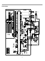
4) circuit and wiring diagram
M - PCB
CN9
5267-14A
R34
5265-13A
1
PK
1
R33
45
R-S
R41
AIN1
KEY INPUT
C29
CN5
R22
4
C14
R3
20K
28
YW
4
R53
29
f2
14
BK
R50
13
12
R21
WHRED
IC4
DATA
13
R43
12
WHPK
12
24
R44
25
4
VASS
11
10
C1 ERROR
R-S
PREVENT OVER
ICE
DATA
11
WHBL
11
R44
26
R-S ON
DATA
R51
10
WHBK
10
R52
37
R-S OFF
DATA
10
P.M.
BA10
BA9
A.M.
e3
d3
e2
d2
e1
9
WH
BA8
LOW
BA6
Economic
BA4
BA7
BA5
c3
c2
FREEZING
ROOM b3
DEODORIZATION
BA3
a3
R54
38
DATA
GY
8
R56
39
12V
34
b2
5
b1
BL
5
C39
IC1
DATA
TWP 47C350N
VCC
a1
5V
11
12
13
10
9
14
8
3
F - PCB
7
8
7805
C2
7
YT
7
R55
GND
C1
9
46
DEFROST
OPTION
R55
R57
C3
7812
C10 C2
C17
0.1µF
0.7
D5
B01
BL
YT
0.1 µF 0.1µF
BL
7806
C1
0.1mf
BK
R79
C13
YFW-800-03
X7
2
X6
5
X5
1
X4
12
X3
15
X2
14
X1
13
X0
YT
DOOR
S/W
RED
5YC581
R75
1
BK
FUSE
1.5A
R77
3
F-FAN
VAR1
RT1
17.8X
R12
14.3K
4
C3202
R14
Q01
23.2K
R15 23.2K
R16 28.6K
BL
R80
1K
4
RED
2
C41
YW
R17 41.2K
R18 24.9K
FAN RELAY
RY3
R
LAMP
F
LAMP
R27
BK
C21
FREQUENCY
INPUT
BK
PCB TRANS
1000µF
IC8
R2
26.3K
11
GY
GY
CN2
6
IC05
470µF
C12
30.1K
C7
a2
IC7
7805
0.1µF
12
c1
B02
C43
5231-04A
12V
5.4V
C22
YW
F-SENSOR
CN3
0.1µF
IC9
30.1K
24.3K
R20
C20
R19
R28
R55
8
MID
9
12V
d1
C40
5V
30.1K
20.5K
R10
R9
R26
8
7812
C3
30.1K
33.2K
R8
C19
1000mf
C44
IC10
37.4K
R7
R25
7
R20
LOW MID
HIGH
R5
R24
C15
R53
Quick
Freezing
12V
C14
6
DATA
R43
5
6
7
8
9
OR
R1
25.5K
C42
2
R43
2
3
C4
1
23
GN
BL
R4
24K
3
VAREF
14
BK
D-SENSOR
CN4
C5
C15
WH
SCAN
R49
1
17
18
f1
F-S
R40
AIN0
C17
R47
12
g1
SCAN
R57
4
8
62783
g2
f3
MID.HIGH
R60
R23
5
R32
i
g3
D-S
R41
AIN2
4051
7
3
R-SENSOR
B-4P-YH
27 SCAN
R30
8
7
2
4
5
7
15
10
13
3
15
16
-
OR
4
14
15
BA2
3
13
13
14
BA1
FRESHNESS
R61
GN
IC3
62308
12
8
4
26
3
7
11
11
24
23
9
17
YFW-800-06
D8
314145
55
P-RELAY
CN1
47 ICE MAKER
OPTION
YW
GN
COMP
R55
C33
50
X-IN
X-TAL
51
20 µF C34
X-OUT
52
HOLD
19
R40
1K
20
21
R41
1K
22
R71
1K
50
C35
X0
C26 C27
WARM/COLD DIFF
X1
COMP ON/OFF DIFF
X2
PRE COOL OFF
X3
SAVE MODE OFF
X4
D-HTR OFF
X8
D1 ERROR
X7
F-S TEMP DISPLAY
R70
IC5
D-TIME
OPTION
(WIN)
51
FAN
OPTION
52
FAN RP4
53
OPTION
R52
48
S8054
R32
D-TIME
OPTION
(DIFF)
RESET
30
C3
31
32
TEST
GND
FAN1
43
5
IC2
34
3
14
COMP 33
HTR 36
41
42
4
13
16
35
2
3
1
6
7
C-FAN
15
PK
D9
COMP RELAY
D10
CN10
YFW-800-01
PK
D4
IN5399
R34
4 IC5
3
PCB
1
2
D6
IN4062
R34
D1
47K
R33
47K
R57
C24
R31
R32
31
R34
GY
TEMP FUSE
70+/-5 Co
RY4
C23
S/C
MTR GLASS
HTR RELAY
C FAN RELAY
DEODORIZATION 18
OPTION
WH
17
20
25
R33
PK
RY2
40
44
53
54
55
57
58
59
POWER 48
15
DOOR
S/W
INPUT
WATER SUPPLY 17
INPUT
GN
12
SN3AC300Y
20 µF
RY1
82304
11
13
7
7
10
IC1
62308
11
2
14
34
2
R59
10
9
3
12
1
5
RED
R31
R07
R04
R03
R02
R01
R06
R05
DD2 SW
DD1 SW
DD5 SW
DD3 SW
DD4 SW
2
IC2
4051
13
POWER CORD
C5
R52
IN4145x5
5273-02A
WH
SN1
AC300Y
Quick Freezing
TIME
ESTABLISHMENT
Economic
R-FAN