1
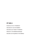
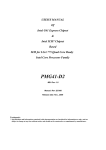
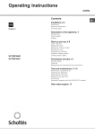
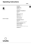
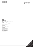
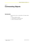
5413143 Issue 1
Oct. 2010
38 cm
GAS HOBS
Models
Covered
Comm.
Code
Single Ring
PMG41DCDRSF
57506
2 Ring
PMG42SF
57507
Service
Information
Scholtès UK
© 2010 Reg. Office: Peterborough PE2 9JB Registered in London: 106725
SAFETY NOTES & GENERAL SERVICING ADVICE
1. All Gas Appliances MUST by law be installed by a competent person. Only use a Gas Safe (Corgi in
Northern Ireland) Registered Engineer. Service or repairs should always be carried out by Scholtès UK
Service personnel.
2. ALWAYS ISOLATE THE APPLIANCE FROM THE GAS, AND WHERE NECESSARY, ELECTRICAL
SUPPLIES BEFORE COMMENCING ANY SERVICE OR REPAIR WORK.
3. Personal safety precautions MUST be taken by engineers to protect against accidents caused by sharp
edges on metal or plastic parts.
4. This Publication is intended for qualified service engineers and all reasonable care has been taken to
ensure that the information contained in the service instructions is correct at the time of printing.
Continued development of products means that specifications and parts are subject to modification and
the information given may not entirely correspond with your appliance.
5. Genuine Scholtès UK spares should always be used when repairing Scholtès UK products.
For UK customers the fitting of non genuine spares could affect your rights under the product liability
section of the Consumer Protection Act 1988.
IF YOU SUSPECT A GAS ESCAPE CARRY OUT THE FOLLOWING
1.
2.
3.
4.
DO turn off the gas supply immediately at the meter.
DO extinguish all sources of ignition.
DO open doors and windows to ventilate the room (s).
DO ensure access can be made to the premises. Where the operation of entry phones or electric security
doors are evident, these MUST NOT BE USED. Access will have to be arranged by another method.
5. If you cannot IMMEDIATELY attend to the gas escape, report the escape to the gas supplier.
Their telephone number can be found in the local telephone directory.
6. DO NOT smoke.
7. DO NOT turn on or off electrical light or power switches.
IF IN DOUBT, EVACUATE THE PREMISES AND IF NECESSARY ADJACENT PROPERTIES.
INDEX
Introduction . . . . . . . . . . . . . . . . . . . . . . . . . . . . . . . . . . . . . . . . . . . . . . . . . . . . . . . . . . 3
Technical Data . . . . . . . . . . . . . . . . . . . . . . . . . . . . . . . . . . . . . . . . . . . . . . . . . . . . . 3 - 5
Disposal . . . . . . . . . . . . . . . . . . . . . . . . . . . . . . . . . . . . . . . . . . . . . . . . . . . . . . . . . . . . . 5
Installation Instructions . . . . . . . . . . . . . . . . . . . . . . . . . . . . . . . . . . . . . . . . . . . . . 6 - 9
Description of the Appliance . . . . . . . . . . . . . . . . . . . . . . . . . . . . . . . . . . . . . . . . . . . 10
Dismantling Procedure . . . . . . . . . . . . . . . . . . . . . . . . . . . . . . . . . . . . . . . . . . . . 11 - 12
Wiring Diagram . . . . . . . . . . . . . . . . . . . . . . . . . . . . . . . . . . . . . . . . . . . . . . . . . . . . . . 13
Service Manual UK
English
2 of 13
INTRODUCTION OF SCHOLTÈS 38cm GAS HOBS MODELS PMG41DCDRSF &
PMG42SF
The above 38 cm Domino Gas Hobs were introduced to the Scholtès range during October 2010.
Model PMG41DCDRSF is a single Double Crown Wok burner gas hob, model PMG42SF is a double
burner gas hob with one Triple Crown burner. Both models have automatic ignition, cast iron pan
supports and FSD fitted on each burner.
Model
Comm. Code
Colour
PMG41DCDRSF
PMG42SF
57506
57507
Stainless Steel
Stainless Steel
TECHNICAL DATA
GENERAL
LPG Conversion Kits are available:
C00090735 model PMG41, C00089138 model PMG42.
COUNTRY OF ORIGIN
Italy
OVERALL DIMENSIONS
Height
54 mm - PMG41, 47 mm - PMG42
Width
380 mm
Depth (front to back)
510 mm
GAS SPECIFICATIONS
Gas Connection
Supply Pressure
Pressure Test Point
Gas Rate Adjustment
Aeration Adjustment
Rp 1/2 (1/2" BSP Male) located on the left hand side of the hob when
viewed from the rear.
Natural Gas Models - G20 @ 20 mbar
Propane (G31) at 37 mbar
Butane (G30) at 28-30 mbar
Burner Injector
None
None
ELECTRICAL SPECIFICATIONS
Electrical Connection
Flexible cord fitted 1.5 m.230/240V AC - 50HZ supply with only a 3 amp
fuse.
Service Manual UK
English
3 of 13
BURNER INPUT RATES & INJECTOR SIZES
Table 1
Liquid gas
Diameter Thermal power
(mm)
kW (H.s.*)
Natural gas
Flow *
g/h
By-pass Injector
1/100
1/100
Injector
1/100
Flow*
l/h
BURNER
Nomin. Reduc.
(mm)
(mm)
G30
G31
(mm)
G20
D. Triple Ring
130
3.25
1.3
57
91
236
232
124
309
A. Auxiliary
55
1.00
0.4
30
50
73
71
71
95
I. Double flame DC DR (internal)
30
0.90
0.4
30
44
65
64
70
86
I. Double Flame DC DR (external)
130
4.10
1.3
57
70
298
293
110
390
28-30
20
35
37
25
45
Nominal
Minimum
Maximum
Supply pressure
*
At 15°C and 1013 mbar - dry gas
**
Propane P.C.S. = 50.37 MJ/Kg
*** Butane
P.C.S. = 49.47 MJ/Kg
Natural
P.C.S. = 37.78 MJ/Kg
20
17
25
The hob can only be installed above built-in ovens with a cooling fan ventilation system.
D
I
A
PMG 42 ...
PMG 41 DCDR ...
Service Manual UK
English
4 of 13
DIRECTIVES
This model conforms with the following European Economic Community directives:
- 2006/95/EEC dated 12/12/06 (Low Voltage) and subsequent amendments;
- 2004/108/EEC dated 15/12/04 (Electromagnetic Compatibility) and subsequent amendments;
- 93/68/EEC dated 22/07/93 and subsequent amendments;
- 2009/142/EEC dated 30/11/09 (Gas) and subsequent amendments;
- 2002/96/EC and subsequent amendments.
DISPOSAL
To minimise the risk of injury to children please dispose of your product carefully and safely.
Remove all doors and lids. Remove the mains cable (where fitted) by cutting off flush with the
appliance and always ensure that no plug is left in a condition where it could be connected to the
electricity supply.
To help the environment, Local Authority instructions should be followed for the disposal of the
product.
Disposal of Old Electrical Appliances
The European Directive 2002/96/EC on Waste Electrical and Electronic Equipment (WEEE), requires
that old household electrical appliances must not be disposed of in the normal unsorted municipal
waste stream. Old appliances must be collected separately in order to optimise the recovery and
recycling of the materials they contain and reduce the impact on human health and the environment.
The crossed out 'wheeled bin' symbol on the product reminds you of your obligation, that when you
dispose of the appliance it must be separately collected.
Consumers should contact their local authority or retailer for information concerning the correct
disposal of their old appliance.
Service Manual UK
English
5 of 13
INSTALLATION INSTRUCTIONS
Prior to installation, ensure that the local distributions (nature of the gas and gas pressure) and the
adjustment conditions are compatible. The adjustment conditions for this appliance are stated on the
data badge which is fitted on the underside of the base panel.
The appliance is not designed to be connected to a combustion products evacuation device.
It must be installed and connected in accordance with current installation regulations.
In particular attention should be given to the relevant requirements regarding ventilation.
The models in this manual are set to burn NATURAL GAS (G20) at 20 mbar. It can be converted for
use on Butane (G30) at 28 - 30 mbar and Propane (G31) at 37 mbar with the use of the conversion kit.
The appliance is supplied with an LPG kit which includes the injectors, together with an LPG label.
The customer is advised to keep the kit in a safe place.
The Conversion Kit for model PMG41 is Part Number C00090735 and for model PMG42 is part
number C00089138.
GAS SAFETY (INSTALLATION & USE) REGULATIONS
It is the law that all gas appliances are installed by competent persons in accordance with the current
edition of the above regulations. It is in your interest and that of safety to ensure compliance with the
law.
In the UK, Gas Safe (CORGI in Northern Ireland) registered installers work to safe standards of
practice.
The hob must also be installed in accordance with BS 6172: 2004.
Failure to install the hob correctly could invalidate the warranty liability claims and could lead to
prosecution.
LOCATION
The hob may be located in a kitchen, kitchen/diner or a bed-sitting room, but not in a room containing
a bath or shower. The hob must not be installed in a bed-sitting room of less than 20m3.
When adjusted for use on Butane (G30) or Propane (G31), this model must not be installed in a room
or internal space below ground level, e.g. in a basement.
PROVISION FOR VENTILATION
The room containing the hob should have an air supply in accordance with BS 5440:Part 2:2009.
The room must have an opening window or equivalent; some rooms may also require a permanent
vent.
If the room has a volume between 5 m3 and 10 m3, it will require an air vent of 50 cm2 effective area
unless it has a door which opens directly to outside.
If the room has a volume of less than 5 m3, it will require an air vent of 100 cm2 effective area.
If there are other fuel burning appliances in the same room, BS5440 Part 2: 2009 should be consulted
to determine air vent requirements.
Service Manual UK
English
6 of 13
SITING THE HOB
All Scholtès hobs are suitable for installation over any Scholtès Built -In Ovens. The hob should be
checked to ensure that the voltage corresponds with the voltage supply, this is stated on the rating
plate which is situated on the base panel.
These hobs are designed to fit into a worktop and base unit(s) with a cut-out as shown in Fig. 1.
Fig. 1
PMG42SF
Gas Inlet
PMG41DCDRSF
Service Manual UK
English
7 of 13
Any obstruction such as supports or side panels, must be removed to allow 15 mm minimum depth
below the base of the gas hob. Any overhead surface of combustible material must not be closer than
650 mm. See Fig. 2 and Fig. 3.
It is recommended that the hob be installed at a distance of at least 55 mm from the rear wall or other
vertical surfaces to ensure that the air circulated properly over the cooking area and to avoid
overheating the surrounding surfaces. See Fig. 3.
Fig. 2
Fig. 3
If a cooker hood is to be installed, refer to the manufacturers instructions regarding fixing heights.
FITTING THE HOB
Unpack the hob from the carton. Remove the bag containing the sealing tape, fixing brackets and
screws. Make sure that the seal adheres properly to the bottom part of the frame of the hob.
The seal must fit properly around the entire hob frame and especially along the corners in order to
create a seal between the work top and the hob itself so as to prevent spills or splashes from leaking
into the cabinet below. The hob must be fixed into the work top using the fixing clamps as shown in Fig.
4 below.
It is essential to install the hob on a totally flat surface. Any damage caused by incorrect fitting may
alter the characteristics or impair performance.
Insert the hob into the hole, pressing firmly around the frame to make it adhere to the counter top.
Connect the hob to the gas supply and check for gas tightness.
Fig. 4
Service Manual UK
English
8 of 13
INSTALLATION - ELECTRICAL REQUIREMENTS
WARNING - REFER TO THE RATING PLATE FOR VOLTAGE AND CHECK THAT THE
APPLIANCE VOLTAGE CORRESPONDS WITH THE SUPPLY VOLTAGE.
THIS APPLIANCE MUST BE EARTHED. CONNECT TO A 230-240V 50Hz SUPPLY ONLY
When connected to a B.S. 1363 fused plug, a 3 amp fuse must be fitted.
IMPORTANT: The wires in the mains lead fitted to this appliance may not correspond with the coloured
marking identifying the terminals in the plug. if this is the case, proceed as follows: The wire which is coloured BLUE must be connected to the terminal which is marked with the N or
coloured BLACK. The wire which is coloured BROWN must be connected to the terminal which is
marked with the letter L or coloured RED.
When wiring the plug, ensure that all strands of wire are securely retained in each terminal. Do not
forget to tighten the mains lead clamp on the plug.
If you are in doubt, consult a qualified electrician.
BLUE
- NEUTRAL
BROWN
- LIVE
GREEN/YELLOW STRIPES
- EARTH
Service Manual UK
English
9 of 13
DESCRIPTION OF THE APPLIANCE
OVERALL VIEW - PMG42 shown
Support Grid for
COOKWARE
GAS BURNERS
Control Knobs for
GAS BURNERS
SAFETY
DEVICES
•
•
•
•
Ignition for
GAS BURNERS
GAS BURNERS differ in size and power. Use the diameter of the cookware to choose the most
appropriate burner to cook with.
CONTROL KNOBS for the gas burners adjust the power and size of the flame.
IGNITION for the gas burner enables a specific burner to be lit automatically.
SAFETY DEVICE stops the flow of gas if the flame is accidentally extinguished.
Service Manual UK
English
10 of 13
DISMANTLING PROCEDURE
WARNING
i) A gas tightness test must be carried out, both before and after completion of any work
involving installation, disconnection, removal, alteration and replacement or
maintenance of any gas appliance, fitting, etc.
ii) Before continuing, ensure that the appliance is disconnected from the electrical supply,
and before servicing any gas carrying component, disconnect the gas supply to the
appliance.
iii) Carry out insulation resistance, Earth continuity and functional tests on the appliance
after service.
iv) Personal safety precautions must be taken to protect against accidents caused by sharp
edges on metal and plastic parts.
1.
a.
b.
c.
d.
e.
f.
TO REMOVE THE HOB TOP
Disconnect the hob from the power supply and the gas supply.
Remove the pan support, burner cap(s), burner ring(s), control knob(s), springs and shrouds.
Remove the 4 screws, 2 per burner, which hold the burners to the hob top.
Remove the 2 screws that secure the 2 control taps to the hob top (1 screw per tap).
Lift the hob top clear.
Reassemble in reverse order.
2.
a.
b.
c.
TO ACCESS THE CONTROLS
Disconnect the hob from the power supply.
Remove the pan support, burner cap(s) and burner rings(s).
Remove the 6 screws on the bottom cover to allow access to the controls.
3.
a.
b.
TO REMOVE THE SPARK GENERATOR
Remove the hob top as in (1).
Remove the Live, Neutral and Earth connections from the spark generator, noting their original
positions.
Remove the 2 electrode leads from the spark generator, noting their original positions.
Remove the 2 screws holding the spark generator to the hob base panel. One of the screws supports
the Earth pin.
Reassemble in reverse order.
c.
d.
e.
4.
a.
b.
c.
d.
e.
TO REMOVE THE BURNER BASE (BASES)
Remove hob top as in (1).
Undo the hexagonal headed nuts holding the bundy tubes onto the burner bases using a
15 mm spanner.
Remove the 2 screws from under the base holding the burner to the base panel. Remove the plate held
by 4 screws and remove the burner.
The small burner has no securing plate - PMG42.
Reassemble in reverse order.
Service Manual UK
English
11 of 13
5.
a.
b.
c.
d.
THERMOCOUPLES
Remove the hob top as in (1).
Undo the 15 mm union nut.
Remove the 2 screws in the burner base. When loose, this will allow access to the 8 mm nut holding
the thermocouple plate.
Reassemble in reverse order.
6.
a.
b
c.
d.
TO REMOVE THE HOB ELECTRODES & LEADS
Remove the hob top as in (1).
Unclip and remove the retaining clip that holds the electrode and lead assembly to the burner base.
Remove the electrode and lead assembly.
Reassemble in reverse order.
7.
a.
b.
c.
d.
TO REMOVE THE CONTROL TAP & MICROSWITCH ASSEMBLIES
Remove the hob top as in (1).
Undo the hexagonal headed nuts securing the bundy tubes to both control taps using a 15 mm spanner.
Remove the screw from under the base holding the gas rail assembly.
Lift clear the gas rail assembly complete with control taps, noting that the Blue leads and microswitches
are still connected.
e. Remove the 2 screws securing the brackets on the gas rail to the control taps. Remove the control tap
assemblies from the gas rail.
f.
Unclip and remove the retaining ring 'C' clip from the spindle of the control tap.
g. Remove the washer.
h. Lift the microswitch assemblies clear, noting the position of all the washers.
i.
Disconnect one Blue lead from the spark generator.
j.
Remove the 2 screws holding the mains terminal block cover plate from the underside of the base.
Remove the cover.
k. Unscrew the Blue microswitch lead from the mains terminal block.
l.
Remove the complete double microswitch assembly from the appliance.
m. Reassemble in reverse order.
NOTES: On reassembly, all gas joints must be checked for leakage.
A new seal is to be used each time the control tap is removed from the gas rail.
8.
a.
b.
TO REMOVE THE BURNER INJECTOR(S)
Remove the pan support, burner cap(s) and burner ring(s).
The injector(s) can be removed by using a 7 mm box spanner.
Service Manual UK
English
12 of 13
WIRING DIAGRAM
Spark Generator
66
Transformer
22
Tf
22
Microswitch
15
Tp
66
66
22 Brown
66 Light Blue
15 Yellow/Green
Terminal Block
N
230V~50Hz
Service Manual UK
L
5413143wd.pdf
PMG41 / PMG42
English
13 of 13