1
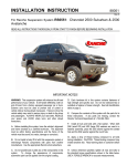
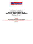
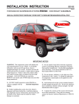
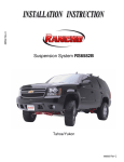
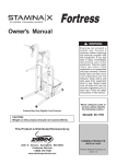
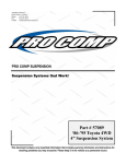
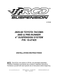
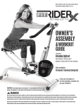
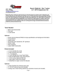
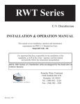
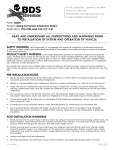
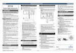
102 S. Michigan Ave., Coldwater, MI 49036
Phone: 517-279-2135
Web/live chat: www.bds-suspension.com
E-mail: [email protected]
Part#: 012511, 012512, 012513
Product: Front Box Kit
Application: Dodge Pickup 4wd
Read and understand all instructions and warnings prior
to installation of system and operation of vehicle.
SAFETY WARNING
BDS Suspension Co. recommends this system be installed by a professional technician.
In addition to these instructions, professional knowledge of disassembly/ reassembly procedures and post installation
checks must be known.
PRODUCT SAFETY WARNING
Certain BDS Suspension products are intended to improve off-road performance. Modifying your vehicle for off-road use may result in the vehicle handling differently than a factory equipped
vehicle. Extreme care must be used to prevent loss of control or vehicle rollover. Failure to drive your modified vehicle
safely may result in serious injury or death. BDS Suspension Co. does not recommend the combined use of suspension
lifts, body lifts, or other lifting devices.
You should never operate your modified vehicle under the influence of alcohol or drugs. Always drive your modified vehicle at reduced speeds to ensure your ability to control your vehicle under all driving conditions. Always wear your seat
belt.
Pre-Installation Notes
1. Special literature required: OE Service Manual for model/year of vehicle. Refer to manual for proper disassembly/
reassembly procedures of OE and related components.
2. Adhere to recommendations when replacement fasteners, retainers and keepers are called out in the OE manual.
3. Larger rim and tire combinations may increase leverage on suspension, steering, and related components. When
selecting combinations larger than OE, consider the additional stress you could be inducing on the OE and related
components.
4. Post suspension system vehicles may experience drive line vibrations. Angles may require tuning, slider on shaft
may require replacement, shafts may need to be lengthened or trued, and U-joints may need to be replaced.
5. Secure and properly block vehicle prior to installation of BDS Suspension components. Always wear safety glasses
when using power tools.
6. If installation is to be performed without a hoist, BDS Suspension Co. recommends rear alterations first.
7. Due to payload options and initial ride height variances, the amount of lift is a base figure. Final ride height
dimensions may vary in accordance to original vehicle attitude. Always measure the attitude prior to beginning
installation.
POST-INSTALLATION WARNINGS
1. Check all fasteners for proper torque. Check to ensure for adequate clearance between all rotating, mobile, fixed, and
heated members. Verify clearance between exhaust and brake lines, fuel lines, fuel tank, floor boards and wiring
harness. Check steering gear for clearance. Test and inspect brake system.
2. Perform steering sweep to ensure front brake hoses have adequate slack and do not contact any rotating, mobile
or heated members. Inspect rear brake hoses at full extension for adequate slack. Failure to perform hose check/
replacement may result in component failure. Longer replacement hoses, if needed can be purchased from a local
parts supplier.
3. Perform head light check and adjustment.
4. Re-torque all fasteners after 500 miles. Always inspect fasteners and components during routine servicing.
rev. 8/7/2014
012511, 012512, 012513 Page 1
PARTS LIST
012511
Part#
02322RB
CTN28
01222
01223
01045
01044
012512
BP123406
QtyDescription
2
1
2
2
1
1
Dodge Blue 5-1/2” Bump Stop
46-7/8”x3”x1” Carton
Lower Control Arm Dodge
Upper Control Arm Dodge
Sway Bar Drop Bracket (PS)
Sway Bar Drop Bracket (DS)
Part#
QtyDescription
082402R
610
1
1
4
16
8
2
10
1
1
1
1
1
1
1
1
1
1
6
12
611
613
6
00-01 Dodge Pitman Arm(DS 200)
Dodge 5 Bolt Pack
1/2” USS washer
1/2” SAE washer
12mm - 1.75mm x 40mm bolt
12mm - 1.75mm x 110mm bolt
12mm - 1.75mm prevailing torque nut
Dodge 5 Bolt Pack
18mm-2.5x70mm bolt
18mm washer
18mm-2.5 torque nut
1/8” x 2” cotter pin
1/2”-13x2-1/2” bolt
1/2” USS washer
1/2” SAE washer
1/2”-13 torque nut
Bolt Pack Dodge 4 Long Arm
9/16” - 12 x 1-1/2” bolt
9/16” SAE flat washer thruhardened
9/16” - 12 prevailing torque nut
Page 2 012511, 012512, 012513
1
Bolt Pack Ford Bump Stop Ext
8
1/4” USS washer
4
1/4” - 20 x 1” bolt
4
1/4” - prevailing torque nut
BP123401 1
Bolt Pack Ford Sway Bar Ext
4
3/8” - 16 x 1-1/4” bolt
4
3/8” - 16 prevailing torque nut
8
3/8” USS thru hardened washer
3522RB
8
Dodge Bushing (BSDG2)
3521RB
8
Dodge Lower 7/8 ID Bushing
516
2
1/4-28 Grease Zert (#60105)
60107
6
90° 1/4-28 Grease Zerk
01257
1
5 Dodge Flat Brake Line Drop
01258
2
Brake Line Drop with Tab
01259
1
Brake Line U Drop Bracket
01262
1
Dodge 5 Track Bar Washer
342701 1Loctite
90-402A8 2
8x10 4mil Poly Bag
Inst Sheet 1
Instruction sheet
Warning CD 1
Warning Card
222780
1
2x6 BDS 2 Color Stickers
CTN36
1
19-1/16”x11-7/8”x6-1/16” Box
A128
1
Sticker Tube
17
2
3/4x.120x2.375 Sleeve-ER W
23
4
3/4x.095x2.25 Sleeve-ER W
24
4
7/8x.120wall x 2.51 Dom Tube
01220
1
Long Arm Bracket Dodge DS
01221
1
Long Arm Bracket Dodge PS
02585
1
Dodge Track Bar Bracket
01251
1
5 Dodge Link Relocate Bracket-D
01252
1
5 Dodge Link Relocate Bracket-P
NOTE: This kit will only fit models manufactured on or after February 9, 1994 due to size of track bar stud.
Installation Instructions
1. Park vehicle on a clean, flat surface and block the rear wheels for safety.
2. Open hood, remove the upper shock nuts and retainers. Remove the three nuts retaining the upper shock tower and
remove the brackets.
3. Raise the front of the vehicle and install jack stands under the frame behind the lower link rear brackets. Support
the front axle with a hydraulic jack.
4. Remove the tires. Remove the brakeline anchor bracket between the upper and lower links behind the coil spring.
Retain mounting bolt.
5. Disconnect the original steering stabilizer from the steering link. Disconnect the track bar from the frame end and
lower down.
6. Disconnect the sway bar at the frame side and lower out of the way. Disconnect the drag link from the pitman arm.
(Fig. 1)
Fig. 1
7. Use a pitman arm puller to remove the pitman arm from the steering sector. Install new BDS drop pitman arm and
retain with original fasteners. Torque to 185 ft-lbs. Do not attach drag link to the pitman arm at this time. (Fig. 2)
Fig. 2
8. Remove lower shock bolts and pull shocks up through the coil spring. Lower the front axle to remove the coil spring,
rubber isolator and 3-bolt shock tower ring.
9. Remove the front bump stops from their pocket by working them back and forth with a large set of channel locks.
10. Mark the lower link adjustment cams and the surrounding reinforcement bracket so you can realign the cams after
installation.
012511, 012512, 012513 Page 3
11. Remove the OE lower control arms from both sides. (Fig. 3)
Fig. 3
12. Remove transfer case skid plate and retain front mounting hardware and rear spacer washers.
13. Place new bracket (01220) on driver’s frame rail with the rear hole aligned with transfer case skid plate bracket
mounting hole (Fig. 4). Place transfer case skid plate washer between new bracket and frame rail. Note: 25-7/8”
center to center distance (old mounting point to new mounting point).
Fig. 4
14. Clamp bracket in place. Ensure that the outside plate is flush against frame rail.
15. Move lines inside frame rail to a position where they will not be damaged when drilling holes
16. Drill 9/16” holes at bracket mounting points, except skid plate mounting hole. Note: Only drill through the outside
portion of the frame rail.
17. Install 9/16”x1-1/2” bolts, washers, and nuts in holes that have just been drilled. Do not crush lines inside of frame.
Torque hardware to110 ft-lbs
18. Repeat for passenger’s side (01221). (Fig. 5)
Page 4 012511, 012512, 012513
Fig. 5
19. Mark a line parallel with the bottom of the frame on the lower control arm pockets and cut old pockets off. (Fig. 6)
Fig. 6
20. Reinstall transfer case skid plate with OE hardware at front mounting location and 1/2” x 1-3/4” hardware at frame
mounting points. Minor grinding required to enlarge hole diameter. Torque hardware to 65 ft-lbs. (Fig. 7)
Fig. 7
21. Grease and install bushings (BSDG1-78) into new control arms.
22.
Follow appropriate step depending on model year:
94-99: Grease and install 24-1 sleeves into non-pitched end, and 42-1 sleeves into pitched end.
00-01: Grease and install sleeves 24-1 into both ends of control arms.
23. Install 90 degree grease zerk into both ends of control arms.
24.
Install new long arm with ‘pitched’ end located in axle pocket, grease zerks facing down. Follow appropriate step
depending on model year: (Fig. 8)
94-99: Use new 5/8” x 4-1/2” bolts, washers, and nuts (#620) in new mounting bracket and OE hardware at axle
pocket
00-01: Use all OE hardware.
012511, 012512, 012513 Page 5
Fig. 8
25. Repeat for driver’s side.
26. Remove the OE upper control arms.
27. Prior to installing the upper link relocation brackets, check the holes on each side of the upper link axle mounts to
ensure that a 12mm bolt fits through them. If not, drill out the holes to 1/2”. (Fig. 9 & 10)
Fig. 10
Fig. 9
28. Install relocation bracket over the original mount (note there is a left/right hand).
Note: The longer lower leg
goes toward the center of the vehicle. Install a 12mm x 110mm (4‑l/2”) bolt using the 3/4 x 2.375” sleeve inside the
original axle mount to maintain spacing.
29. Install the shorter bushings and sleeves into the upper links. Install the upper link by sliding them through the
relocation bracket to the original frame mount. Install original bolts, but do not tighten at this time.
30. Remove the screw retaining the steel vacuum lines to the passenger’s side of the frame at the drop point going to the
vacuum actuator valve. Install the furnished drop bracket (1” wide x 4” long) using the original screw at the frame.
Use the supplied 1/4 x 1” bolt, nut and washer to attach the vacuum line to the new drop bracket.
31. Unplug the electrical line at valve and release the plastic clip at the bracket. If additional slack is needed, remove
wire from top of crossmember and route it under the crossmember.
32. Begin installing track bar drop bracket by first removing the brakeline clamp screw from the crossmember. This is
located next to the original frame mount for the track bar. After removing the screw push the brakeline up approximately 2” for clearance.
33. First, check the track bar frame mount to ensure that it is a smooth surface. Some models have a reinforcement
gusset on the edge of the mounting point. This must be ground off to make a flat mounting point for the new bracket.
It is vital that the new bracket mounts to a flat smooth surface.
34.Apply loctite to end of 18mm bolt. Hold new drop bracket up to OE mount. Insert 18mm bolt through the original
mount and the drop bracket and start the nut with washer. Tighten the nut until it is snug.
Page 6 012511, 012512, 012513
35. Twist the drop bracket until the extension brace hits the back of the crossmember. The brace should sit flat against
the crossmember.
36. Use a 1/2” drill and start through the hole in the supplied brace and drill through the crossmember being sure to
come out just below the weld mount on the front side of the crossmember. It may help to drill a smaller pilot hole and
then open to 1/2”. (Fig. 11)
Fig. 11
37. Install a 1/2 x 2-1/2” bolt with washer through the brace and crossmember. On the front side of the crossmember
install the step washer over the weld mount to create a flat surface. Install the nut and torque to 70-75 ft-lbs. Be
sure not to crush the crossmember. Then torque the 18mm bolt to 200 ft-lbs. (Fig. 12)
Fig. 12
38. Move the brake line clamp back down and drill a new 19/64” hole.
39. Install new poly bumpstops in the original pockets. A jack may be used to force the bumpstops into the original
pocket or use a wood block and a 2x4 for leverage.
40.Insert 3-bolt shock tower ring inside the top of the coil tower. Start a couple of nuts on the ring to hold it up in place.
See dual shock instructions if installing.
41. Install coil springs and place rubber isolators on the tops of the coils. Turn the coils so the end of the bottom wraps
is toward the center of the vehicle. Lift up on jack under the differential to place a small load on the coils to hold
them in place.
42. Remove the nuts that you previously installed on the 3-bolt ring. Install new shocks down through the coils springs
and install bolt at the bottom. Install original shock tower bracket over the 3-bolts of the ring. Install nuts on the 3
bolts and tighten. Install shock to the top of the tower with the shock fasteners per their instructions. (If installing
dual shocks, refer to those instructions at this time.
43. Install the supplied brake line relocation brackets at this time. The brackets are the two with a small 90 degree
bend. Install the bracket with the small leg at the bottom facing toward the front of the vehicle. Install original
metric bolt in the bottom hole on the bracket and tighten. Attach the original brake line anchor bracket to the top
hole of the new bracket with the supplied 1/4 x 1” bolt, nut, and washer supplied and tighten. (Fig. 13)
012511, 012512, 012513 Page 7
Fig. 13
44.Loosen the turn buckle clamps on the drag link and rotate 180 degrees. This will allow the drag link to be connected
with the new pitman arm. Install drag link into pitman arm and Torque OE nut to 80 ft.lbs. Be sure to use a new
cotter pin. Rotate the turn buckle clamps to the top side of the drag link to gain clearance for the steering stabilizer.
Tighten turn buckle clamps to 45ft.lbs.
45. Install new BDS steering stabilizer at this time.
46.Swing sway bar back up to the frame mounts. Install sway bar drop brackets between the sway bar and the frame
with the supplied 3/8 x 1” bolts, nuts, and washers. The solid side of the bracket should be facing out and should
slope toward the bumper. Torque bolts to 35ft.lbs.
47. Install tires and lower vehicle to the ground.
48.Attach the track bar to the track bar relocation bracket with the original fasteners and tighten to the following
specifications. Install new cotter pin. Tighten track bar at axle end.
Ball Stud Nut............... 70 ft. lbs.
Axle Bracket Bolt.......... 130 ft. lbs.
49. Tighten upper and lower link bolts making sure the alignment cams are in line with the original marks.
Lower Arm:
Axle Nut....................... 140 ft. lbs.
Frame Nut.................... 140 ft. lbs.
Upper Arm:
Axle Nut....................... 120 ft. lbs.
Frame Nut.................... 120 ft. lbs.
50. Complete a fu ll steering cycle to ensure that nothing is hitting. Check the clearance between the sway bar end links
and the drag link tie rod assembly. It may be necessary to trim/grind for needed clearance.
Notice to Dealer/Installer
These instructions, the warning card, and included decals must be given to the owner of this BDS Suspension product.
For questions, technical support and warranty issues relating to this BDS Suspension product, please contact your distributor/installer before contacting BDS Suspension directly.
Sold/Installed by:
Page 8 012511, 012512, 012513