1
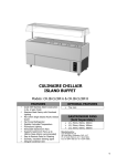
Catalogue 2011/2012
SOLPLUS Inverters and Accessories
Solutronic,
the company
Headquarters
In light of our constant growth
and the increasing size of
our workforce, Solutronic AG
moved on 1 April 2010 to larger
premises just a few miles away
in Köngen. Köngen is located
at the centre of Germany’s
modern industrial heartland in
the south-west of the country
and is very easy to reach by road
(just off the A8 Stuttgart-Munich
motorway) and air, with Stuttgart Airport just 30 miles up the
motorway.
Production
All of our products are made
exclusively in Germany, where
we cooperate with selected
renowned partners. Our strategy
of outsourcing production has
two great advantages: it means
we are exceedingly flexible
with regard to capacity and we
can concentrate on our core
competencies, development and
marketing. For the focus of our
efforts is on our customers and
our product.
Karlsruhe
B 313
Offenburg
Stuttgart
Köngen
0
Ulm
A5
A 81
München
Singen
Schaffhausen
A8
0
The Company
Solutronic AG was founded in
2004 as Solutronic GmbH by
Sibylle and Wieland Scheuerle.
Our goal was to break into
and establish ourselves as a
pioneer and trendsetter in the
regenerative-energy market by
developing a new, state-of-theart generation of grid-connected
solar inverters. Since then, we
have developed and expanded a
range of inverters and add-ons
that have established Solutronic
as an innovative manufacturer
of solar inverters with intelligent
communications functions. We
are constantly working on improving our existing products and
on developing new inverters and
other associated pieces of equipment. Since November 2010 we
are listed on the Frankfurt Stock
Exchange’s Entry Standard.
Lindau
The Team
Our team in Köngen covers the
fields of hardware and software development, laboratory
research, second level service
and test equipment development.
Everyone at Solutronic is working
flat out to continuously optimise
all of our products and to make
them even more efficient.
Our team also includes experts in
domestic and global sales, order
handling, product management,
marketing and PR as well as
customer service and support.
Our staff are always available
to answer any questions and
queries you may have. Thanks to
our flat hierarchy, all decisions
made are implemented quickly
and directly with you in mind.
SOLPLUS Inverters
Catalogue 2011/2012
Index
Page
SOLPLUS 15 inverter
Technical Data
2
3
SOLPLUS 25 – 55 inverters
Accessories
Technical Data
4
6
8
SOLPLUS 100 / 120 inverters
Accessories Technical Data 12
14
16
DE-ICING BOX
Technical Data
Accessories 18
19
19
SOLCOMBOX
Accessories Technical Data
20
20
21
Yield monitoring with master-slave networking 22
Yield monitoring with the aid of the sensor box
Technical Data
23
23
Energy Management with SOLPLUS inverters
24
SOLPLUS+ basic functions and Comfort version
26
SOLPLUS+ Professional and SOLVOLT
28
Communication and network accessories
29
Service 23
Warranty Conditions
24
SOLPLUS Inverters
SOLPLUS 15
SOLPLUS 15
Operating conditions
This inverter is suitable for
installation in small systems. It
stands out thanks to its small
and compact design and the fact
that the number of communication interfaces has been kept to
a minimum. By combining several
inverters in one PV installation,
it‘s also possible to make optimum photovoltaic use of small
roof areas that face in different
directions and have different
shadowing conditions.
Power rating range
The inverter has a rated power
output of 1.5 kW.
Operating principle and
installation planning
The SOLPLUS 15 is a transformerless, single-phase, grid-
connected inverter equipped
with a boost converter. The wide
input voltage range facilitated by
the boost converter allows for a
broad assortment of modules to
be connected.
Grid monitoring
All inverters are equipped with
a software-controlled, grid monitoring function that measures
the grid frequency, impedance
and grid voltage of the inverters
at regular intervals.The requirements differ from country to
country and installation settings
can be adjusted to comply with
national requirements and the
peculiarities of national grid
systems by means of the Setup
menu. The safety-relevant
parameters are protected by
various password levels.
Communications model
All inverters are equipped with
an Ethernet port that offers an
inexpensive and fast way to read
out the data via the internet. Two
M12 plug-in connectors facilitate
communication between the
inverters. In addition, an optional
plug-in AC adapter can be
connected to these connectors
so that communication can also
be continued through the night.
The cheapest method of remotely
monitoring the inverters is to use
their built-in Ethernet port.
Language selection
The language can be selected
from the Setup menu at the start
of installation. The Customer
menu of the inverter supports
English, Germany, French and
Italian.
Approvals/certification
(planned)
CE
VDEW 0126-1-1
ENEL DK5940
AS 4777.2
Availability
Market launch of the inverter is
scheduled for Q4 of 2011.
DC options
To make it easier to connect
the inverters to the connections
on the solar modules, we
currently offer two different DC
connector options: Tyco and
Lumberg (compatible with MC4).
SOLPLUS 15
Technical Data
Security
DC circuit breaker ✓
All-pole-sensitive leakage
✓
current monitoring unit
Earth fault monitoring
✓
Lockable front
✓
Kind of grid monitoring
DC input
single-phase (according to VDE 0126)
Protection class II
IEC 62103 / DIN EN 62109
Max. DC power
1800 W
Max. DC voltage
600 V
DC start voltage
100 V
Display, two-colour LED LCD display*,20 signs, 4-line
Rated input voltage
350 V
Language
Ger / Eng / Spa / Fre / Ita / Tur/ Cze
Max. MPP voltage
500 V
Data logger
integrated, freely programmable
Min. MPP voltage
175 V
Memory size
30 KB / 1MB
Max. input current
8.5 A
Interface
RS485, Ethernet
Number of MPP trackers
1
AC output
Nominal AC output
1500 W
Max. output AC
1650 W
Max. AC output voltage
253 V
Min. AC output voltage
210 V
Nominal output voltage
230V
Max. output current
7A
Distortion factor
<4%
Rated frequency
50 Hz
Min. frequency
47.5 Hz
Max. frequency
52.5 Hz
Rated power factor
> 0.99
Communication
Efficiency
Max. efficiency
> 96.0 %*
Euro ETA > 95.0 %*
Efficiency curve SOLPLUS 15
Mechanical data
250 x 280 x 90*
Weight
5 Kg*
Internal consumption at night
0.01 W
Ambient temperature
-20 °C … +60 °C
Internal consumption at day
<4W
Derating
from +45 °C
Input from
<8W
Topology
transformerless
Cooling concept
free convection
Noise emission
< 35 db(A)
Conformity www.solutronic.de
Max. humidity
90 %
EU conformity ✓
DC-plug in
1
VDEW conformity
in preparation
Protection class
IP 65
ENEL DK5940
in preparation
AC connection
Amphenol ecomate
AS 4777.2
in preparation
DC connection
MC4, Tyco Warranty
6 years
12 years optional
Dimensions in mm
Subject to change without notice. Errors excepted. * preliminary
Efficiency
Conformity and warranty
SOLPLUS Inverters
SOLPLUS 25 – 55
Further
information
is available in:
SOLPLUS 25 – 55 Installation Instruction
SOLPLUS 25 – 55 User and Service Manual
SOLPLUS 25 – 55 IP 21 version
SOLPLUS 25 – 55 IP 54 version
Operating conditions
The SOLPLUS 25 – 55 inverters
are suitable for installing in small,
medium-sized and large systems.
They are available in two different
enclosure variants, compliant
with IP 21 or IP 54, and feature
a fully integrated communication
platform. Our customers get
everything they want from a PV
inverter, and can still connect
optional extras with ease.
Power rating range of the
SOLPLUS inverters
SOLPLUS 25 = 2.5 kW
SOLPLUS 35 = 3.8 kW
SOLPLUS 50 = 4.6 kW
SOLPLUS 55 = 5.5 kW
Operating principle and
installation planning
Solutronic‘s SOLPLUS 25 – 55
inverters are transformerless,
single-phase, grid-connected,
solar inverters. All VDEW regulations that relate to single-phase
inverters must be complied with
in Germany. Thanks to their
capability SOLPLUS 25 - 50
inverters can be operated as
standalone devices.
When SOLPLUS 55 inverters are
being installed, attention must be
paid when configuring the system
to ensure the system phases are
utilised uniformly.
In the case of installations with a
nominal AC power rating >30 kW,
it‘s also necessary to monitor the
phase, this function being implemented in the inverter software.
The function can programmed
once a master-slave network has
been set up.
Grid monitoring
All inverters are equipped with a
software-controlled, grid monitoring function that measures the
grid frequency, impedance and
grid voltage of the inverters at
regular intervals. The requirements differ from country to
country and installation settings
can be adjusted to comply with
national requirements and the
peculiarities of national grid
systems. The safety-relevant
parameters are protected by
various password levels.
In the event of unfavourable
circumstances, utility companies must be able to reduce the
output of installations with a
nominal AC power rating >100
kW. This is done by means of
the master-slave network and a
SOLCOMBOX (see page 20) with
Power Reduction Card.
Approvals/certification
CE
VDEW 0126-1-1
ENEL DK 5940
AS 4777.2
315 mm
303 mm
130 mm
130 mm
450 mm
440 mm
510 mm
70 mm
80 mm
80 mm
50 mm
50 mm
IP 21
appropriate enclosure variant in
order to ensure that the inverters
will enjoy a very long service life.
When planning the entire installation, make sure the inverters are
installed adequately spaced and
with sufficient clearance from
other equipment in the installation area. We recommend a
clearance of 30-50 cm one either
side and min. 20 cm above and
below each unit.
Further detailed information
can be found in the installation
instructions we supply with the
inverters.
The inverters are mounted with
the aid of a mounting bracket
that is fixed to the wall by four
screws.
285 mm
32 mm
Mounting
bracket
20 mm
12 mm
Language selection
Each inverter supports four different languages. When ordering
your units, please choose the
combination of languages (language pack) you want and select
the language you want to use as
your default language. You can
change the language used by
your installation later if you want
(from among the four languages
in the language pack).
IP 54
290 mm
Selecting enclosure variant
The IP 21 enclosure has ventilation slots at the sides to guarantee optimum ventilation and
cooling. All ports and connections on the inverter are easily
accessed. This variant is suitable
for all dust-free indoor areas.
The enclosed and dust-protected
IP 54 variant is fitted with a
temperature-controlled fan for
optimum heat dissipation. The
inverters are splashproof and
suitable for semi-outdoor use.
Selecting DC options
To make it easier to connect the
inverters to the connections on
the solar modules, we currently
offer two different DC connector
options: Tyco and Lumberg 4*
(*compatible with MC4).
Installation instructions
We recommend that you take
very great care when choosing
the installation position and
250 mm
245 mm
20 mm
How to order
Your order should contain the following information:
Power rating/Degree of protection-DC option/No. of strings-Language pack-Default language
Example: SP25/IP54-TYC/2-de/cz/fr/it-1
Note: We are only able to handle an order if you state the power rating and degree of protection you
require. If you fail to include the other specifications in your order, we will supply you with our standard
version inverter (specifications in brackets).
To determine the correct order designation for the inverter you require, please go through each of the
following points and write down the abbreviated order code for the variant you want:
• Select the power rating: SP 25, SP 35, SP 50, SP 55
• Select the degree of protection: IP 21, IP 54
• Select the DC option: LC4, TYC (Standard: TYC)
• Select the no. of strings on the DC side: 2 or 3 (Standard: 2)
• Select the language pack (Standard: de/cz/fr/it)
Language pack de/cz/fr/it = German, Czech, French, Italian
Language pack de/en/es/tr = German, English, Spanish, Turkish
Language pack de/en/fr/it = German, English, French, Italian
Language pack de/en/es/cz= German, English, Spanish, Czech
• Select the default language from the language pack (Standard: 0)
Language
Language
Language
Language
Subject to change without notice. Errors excepted.
pack
pack
pack
pack
de/cz/fr/it
de/en/es/tr
de/en/fr/it
de/en/es/cz 0
German
German
German
German
1
Czech
English
English
English
2
French
Spanish
French
Spanish
3
Italian
Turkish
Italian
Czech
Communication and
installation monitoring
accessories
for SOLPLUS 25 – 55
Patch adapter for X2 for
IP 21 enclosure
Patch adapter for fast setting-up
of the master-slave network via
the X2 RS485 port using patch
cables, for IP 21 enclosure.
Patch adapter for X2 for
IP 54 enclosure
Patch adapter for fast setting-up
of the master-slave network via
the X2 RS485 port using patch
cables, for IP 54 enclosure.
Lumberg DC mating
connector (MC4)
For connecting the solar modules
to the inverter, for MC 4 and
Lumberg 4* (*compatible with
MC4).
Order reference:
PATCHADX2-IP21
Order reference:
PATCHADX2-IP54
Order reference:
STDC-LC
AC mating connector
3-pin AC connection
from Wieland Electric.
Plug-in AC adapter*
Plug-in AC adapter, incl. 1.5 m
cable, for night-time operation.
An AC adapter is needed to
supply power for retrieving data
from the inverter when the photovoltaic generator is inactive:
12 V/300 mA
USB/RS485 adapter for
wiring
USB/RS485 adapter for reading
out the data of an inverter at the
RS485 port via the USB port of
the PC. The set contains a USB
extension cable and a 0.7 m-long
adapter cable: for standard
wiring.
USB/RS485 adapter for
patch adapter
USB/RS485 adapter for reading
out the data of an inverter at the
RS485 port via the USB port of
the PC. The set contains a USB
extension cable and a 0.7 m-long
adapter cable: for connecting
with patch adapters.
Order reference:
NTZ-SP25-55
Order reference:
USB/RS485-D
Order reference:
USB/RS458-P
Order reference:
STAC-SP25-55
*Europlug
Tyco mating connector
For connecting the solar modules
to the inverter, for Tyco.
Order reference:
STDC-TYC
PV module
PV module
Communications model
All SOLPLUS 25 – 55 inverters allow all methods of data retrieval
to be either connected directly
to each individual inverter or be
built into each inverter. Each
inverter is equipped with two
serial ports as well as analogue
and digital inputs and outputs
to enable special functions to
be integrated. The cheapest
method of remote-monitoring the
inverters is to use their built-in
Ethernet port.
PV module
GSMI/GSME
SOLPLUS 50
SOLPLUS 50
SOLPLUS 50
SOLCOMBOX
RS485
TCP/IP
RS232
TCP/IP
TCP/IP
Network cable
DE-ICING BOX
RS485
SOLPLUS
PC
W-LAN
Network cable
Switch
Optional
Power Reduction Card
Analogue
AMOI
(Analogue
modem)
Large display
Sensorbox
SOLPLUS
Connection
to SolarLog,
IP-Lon etc.
Router
E-Mail
RS232
Network cable
SOLVOLT
GSM
TCP/IP
RS485
Telephone line
RS485
PC
Internet
SOLPLUS
Modem
PC
PC: www.solvolt.de
Mobile
phone
RS485 option card
RS485 option card for connecting several communication
interfaces. An additional RS485
option card, for example, must
be used for simultaneous use of
master-slave data communication
and a large display.
Built-in analogue modem
Built-in analogue modem for remote retrieval of data from max.
32 inverters. The built-in modem
card allows remote data retrieval
without additional hardware and
power supply, and with minimal
power consumption.
Order reference:
OKRS485
Order reference:
AMOI
Built-in GSM modem
GSM modem for remote retrieval
of data from max. 32 inverters.
Data retrieval via GSM without
connecting to a telephone line.
Aerial extension cable
for GSM
10 m extension cable for GSM
aerial.
Order reference:
GSMAK-m
Order reference:
GSMI
Subject to change without notice. Errors excepted.
External GSM modem
GSM modem for external and
mobile connection to an inverter
for remote retrieval of data from
max. 32 inverters (incl. adapter
cable and plug-in AC adapter).
Data retrieval via GSM without
connecting to a telephone line.
Order reference:
GSME
Boot dongle
Boot dongle for installing
new firmware with the software
program SOLBoot over RS232.
Order reference:
BD
USB/RS232 adapter
USB/RS232 adapter for reading
out the data of an inverter
connected to the RS232 port via
the USB port of the PC. The set
contains a USB extension cable.
Order reference:
USB/RS232
SOLPLUS 25
Technical Data
Security
DC circuit breaker ✓
All-pole-sensitive leakage current monitoring unit
✓
Earth fault monitoring
✓
Lockable front
–
Kind of grid monitoring
DC input
Protection class II
IEC 62103 / DIN EN 62109
Max. DC power
3000 W
Max. DC voltage
850 V
DC start voltage
380 V
Display
20 signs, 4-line
Rated input voltage
450 V
Language
Ger / Eng / Spa / Fre / Ita / Tur/ Cze
Max. MPP voltage
750 V
Data logger
integrated, freely programmable
Min. MPP voltage
345 V
Memory size
30 KB
Max. input current
8.7 A
Interface
RS485, RS232, Ethernet
Number of MPP trackers
1
AC output
Nominal AC output
2500 W
Max. output AC
2850 W
Max. AC output voltage
253 V
Min. AC output voltage
210 V
Nominal output voltage
230 V
Max. output current
10.9 A
Rated power
2500 W
Distortion factor
2%
Rated frequency
50 Hz
Min. frequency
49.8 Hz
Max. frequency
50.2 Hz
Rated power factor
> 0.99
single-phase (according to VDE 0126)
Mechanical data
Communication
Efficiency
Max. efficiency
97.2 %
Euro ETA 96.6 %
Efficiency curve SOLPLUS 25
Efficiency
Dimensions in mm (W x H x D) IP 21 450 x 303 x 130
Internal consumption at night
0.01 W
Dimensions in mm (W x H x D) IP 54 510 x 315 x 130
Internal consumption at day
<9W
Weight IP 21 / IP 54
18 Kg / 21 Kg
Input from 10 W
Ambient temperature
-20 °C … +60 °C
Derating
+40 °C
Topology
transformerless
Conformity www.solutronic.de
Cooling concept
free convection
EU conformity ✓
VDEW conformity
✓
Noise emission
< 35 db(A)
Conformity and warranty
Max. humidity
90 %
ENEL DK5940
✓
DC-plug in
2 / 3
AS 4777.2
✓
Protection class
IP 21 / IP 54
Warranty
6 years
AC connection
Wieland RST (RST25I3S)
12 years optional
DC connection
Tyco / C4* (*MC4 compatible)
SOLPLUS 35
Technical Data
Security
DC circuit breaker ✓
All-pole-sensitive leakage
✓
current monitoring unit
Earth fault monitoring
✓
Lockable front
–
Kind of grid monitoring
DC input
single-phase (according to VDE 0126)
Protection class II
IEC 62103 / DIN EN 62109
Max. DC power
4350 W
Max. DC voltage
850 V
DC start voltage
380 V
Display
20 signs, 4-line
Rated input voltage
450 V
Language
Ger / Eng / Spa / Fre / Ita / Tur/ Cze
Max. MPP voltage
750 V
Data logger
integrated, freely programmable
Min. MPP voltage
345 V
Memory size
30 KB
Max. input current
12.5 A
Interface
RS485, RS232, Ethernet
Number of MPP trackers
1
AC output
Nominal AC output
3800 W
Max. output AC
4000 W
Max. AC output voltage
253 V
Min. AC output voltage
210 V
Nominal output voltage
230V
Max. output current
16.5 A
Rated power
3800 W
Distortion factor
2%
Rated frequency
50 Hz
Min. frequency
49.8 Hz
Max. frequency
50.2 Hz
Rated power factor
> 0.99
Efficiency
Max. efficiency
97.3 %
Euro ETA 96.8 %
Efficiency curve SOLPLUS 35
Mechanical data
Communication
Efficiency
Dimensions in mm (W x H x D) IP 21 450 x 303 x 130
Internal consumption at night
0.01 W
Dimensions in mm (W x H x D) IP 54 510 x 315 x 130
Internal consumption at day
<9W
Weight IP 21 / IP 54
18 Kg / 21 Kg
Input from
10 W
Ambient temperature
-20 °C … +60 °C
Derating
+40 °C
Topology
transformerless
Conformity www.solutronic.de
Cooling concept
free convection
EU conformity ✓
Noise emission
< 35 db(A)
VDEW conformity
✓
Max. humidity
90 %
ENEL DK5940
✓
DC-plug in
2 / 3
AS 4777.2
✓
Protection class
IP 21 / IP 54
Warranty
6 years
AC connection
Wieland RST (RST25I3S)
12 years optional
DC connection
Tyco / LC4* (* MC4 compatible)
Subject to change without notice. Errors excepted.
Conformity and warranty
SOLPLUS 50
Technical Data
Security
DC circuit breaker ✓
✓
All-pole-sensitive leakage current monitoring unit
Earth fault monitoring
✓
Lockable front
–
Kind of grid monitoring
DC input
Protection class II
IEC 62103 / DIN EN 62109
Max. DC power
6000 W
Max. DC voltage
850 V
DC start voltage
380 V
Display
20 signs, 4-line
Rated input voltage
450 V
Language
Ger / Eng / Spa / Fre / Ita / Tur/ Cze
Max. MPP voltage
750 V
Data logger
integrated, freely programmable
Min. MPP voltage
345 V
Memory size
30 KB
Max. input current
16.2 A
Interface
RS485, RS232, Ethernet
Number of MPP trackers
1
AC output
Nominal AC output
4600 W
Max. output AC
5000 W
Max. AC output voltage
253 V
Min. AC output voltage
210 V
Nominal output voltage
230V
Max. output current
21.7 A
Rated power
4600 W
Distortion factor
2%
Rated frequency
50 Hz
Min. frequency
49.8 Hz
Max. frequency
50.2 Hz
Rated power factor
> 0.99
10
single-phase (according to VDE 0126)
Efficiency
Max. efficiency
97.4 %
Euro ETA 97 %
Efficiency curve SOLPLUS 50
Mechanical data
Communication
Efficiency
Dimensions in mm (W x H x D) IP 21 450 x 303 x 130
Internal consumption at night
0.01 W
Dimensions in mm (W x H x D) IP 54 510 x 315 x 130
Internal consumption at day
<9W
Weight IP 21 / IP 54
19 Kg / 22 Kg
Input from 10 W
Ambient temperature
-20 °C … +60 °C
Derating
+40 °C
Topology
transformerless
Conformity www.solutronic.de
Cooling concept
free convection + aerator
EU conformity ✓
Noise emission
< 35 db(A)
VDEW conformity ✓
Max. humidity
90 %
ENEL DK5940
✓
Max. number of strings 2/3
AS 4777.2
✓
Protection class
IP 21 / IP 54
Warranty
6 years
AC connection
Wieland RST (RST25I3S)
12 years optional
DC connection
Tyco / LC4* (* MC4 compatible)
Conformity and warranty
SOLPLUS 55
Technical Data
Security
DC circuit breaker
✓
All-pole-sensitive leakage
✓
current monitoring unit
Earth fault monitoring
✓
Lockable front
–
Kind of grid monitoring
DC input
single-phase (according to VDE 0126)
Protection class II
IEC 62103 / DIN EN 62109
Max. DC power
6600 W
Max. DC voltage
850 V
DC start voltage
380 V
Display
20 signs, 4-line
Rated input voltage
450 V
Language
Ger / Eng / Spa / Fre / Ita / Tur/ Cze
Max. MPP voltage
750 V
Data logger
integrated, freely programmable
Min. MPP voltage
345 V
Memory size
30 KB
Max. input current
17.4 A
Interface
RS485, RS232, Ethernet
Number of MPP trackers
1
AC output
Nominal AC output
5500 W
Max. output AC
5800 W
Max. AC output voltage
253 V
Min. AC output voltage
210 V
Nominal output voltage
230V
Max. output current
24 A
Rated power
5500 W
Distortion factor
2%
Rated frequency
50 Hz
Min. frequency
49.8 Hz
Max. frequency
50.2 Hz
Rated power factor
Communication
Efficiency
Max. efficiency
97.4 %
Euro ETA 97 %
Efficiency curve SOLPLUS 55
> 0.99
Mechanical data
Efficiency
Dimensions in mm (W x H x D) IP 21 450 x 303 x 130
Internal consumption at night
0.01 W
Dimensions in mm (W x H x D) IP 54 510 x 315 x 130
Internal consumption at day
<9W
Weight IP 21 / IP 54
19 Kg / 22 Kg
Input from 10 W
Ambient temperature
-20 °C … +60 °C
Derating
+40 °C
Topology
transformerless
Conformity www.solutronic.de
Cooling concept
free convection + aerator
EU conformity ✓
VDEW conformity ✓
Noise emission
< 35 db(A)
Conformity and warranty
11
Max. humidity
90 %
ENEL DK5940
✓
Max. number of strings 2/3
AS 4777.2
✓
Protection class
IP 21 / IP 54
Warranty
6 years
AC connection
Wieland RST (RST25I3S)
12 years optional
DC connection
Tyco / LC4* (* MC4 compatible)
Subject to change without notice. Errors excepted.
SOLPLUS Inverters
SOLPLUS 100 / 120
Further
information
is available in:
SOLPLUS 100/120 Installation Instruction
SOLPLUS 100/120 User and Service Manual
SP 100 / 120
12
Operating conditions
These inverters are suitable for
installation in medium-sized and
large-scale systems. Their compact design means that they are
quick to service even when part
of large installations. Such string
inverters enable large-scale systems to be set up cost-effectively, while guaranteeing high yields
and optimised servicing.
Power rating range
These inverters cover the nominal AC power ratings 10.0 kW
and 12.5 kW.
Principle
Solutronic‘s SOLPLUS 100 and
SOLPLUS 120 inverters are
transformerless, three-phase,
grid-connected, solar inverters.
Each phase has its own MPP tracker, so that each MPP tracker
can be assigned individually. This
in turn enables the inverters to
be used in installations in which
the modules are installed on
differently pitched roofs.
Grid monitoring
Monitoring of the grid is performed by monitoring the phases
connected, even in the case of
installations with a nominal AC
power rating >30kW. In the event
of unfavourable circumstances,
utility companies must be able to
reduce the output of installations
with a nominal AC power rating
>100 kW. This is done by means
of the master-slave network and
a SOLCOMBOX (see page 20)
with Power Reduction Card.
Approvals/certification
CE
VDEW 0126-1-1
ENEL DK 5940
Languages
All language versions offered by
Solutronic are integrated in every
inverter. You set the language
you want by means of a selection
menu.
Enclosure
The enclosure of the inverters
is compact. Thanks to their high
level of efficiency, the inverters
are cooled solely by means of
their heat sink. The enclosure
fulfils IP 65 and all connectors
also comply with this degree of
protection when plugged in. To
ensure this level of protection,
suitable dummy plugs must be
fitted if DC options are not used.
We also supply suitable mating
connectors as an option for making an IP 65-compliant Ethernet
connection.
230 mm
620 mm
400 mm
120 mm
110 mm
Selecting DC options
To make it easier to connect the
inverters to the connections on
the solar modules, we currently
offer two different DC connector
options: Tyco and Lumberg 4*
(*compatible with MC4). All inverters are delivered with connectors for two strings per tracker.
Installation instructions
During the development and
design phases, importance was
attached to keeping the enclosure lightweight in order to make
it easier to handle. The actual
inverter weighs 40 kg, far less
than other inverters of the same
power rating. For safety reasons,
we recommend installation be
carried out by two people.
The inverter is mounted to the
wall with the aid of a bracket,
which should be mounted to the
wall first, to simplify installation
of the inverter.
Mounting bracket
620 mm
The inverters can be mounted
without having to ensure a minimum lateral clearance between
them and other inverters because they are cooled by downward
convection from top to bottom.
However, we still recommend
a clearance of 15 cm on either
side of each unit in order to
make servicing the inverter installation easier.
How to order
Your order should contain the following information:
Power rating-DC option
Example: SP120-TYC
Note: We are only able to handle an order if you state the power
rating you require. If you fail to include the specifications of the DC
option in your order, we will supply you with our standard version
inverter (specifications in brackets).
To determine the correct order designation for the inverter you
require, please go through the following two points and write
down the abbreviated order code for the variant you want:
• Select the power rating: SP 100, SP 120
• Select the DC option: LC4, TYC (Standard: TYC)
Subject to change without notice. Errors excepted.
110 mm
85 mm
490 mm
250 mm
400 mm
500 mm
350 mm
14 mm
110 mm
30 mm
52 mm
12 mm
47 mm
13
Communication and
installation monitoring
accessories for SOLPLUS 15
and SOLPLUS 100 / 120
14
Dummy plug for Tyco
connector
To ensure protection in compliance with IP 65, the DC connectors must be sealed with dummy
plugs for Tyco connectors.
Dummy plug for Lumberg
connector (LC4)
To ensure protection in compliance with IP 65, the DC connectors must be sealed with dummy
plugs for Lumberg connectors.
Lumberg DC mating
connector (MC4)
For connecting the solar modules
to the inverter, for MC 4 and
Lumberg 4* (*compatible with
MC4).
Order reference:
BST-TYC
Order reference:
BST-LC
Order reference:
STDC-LC
AC mating connector
5-pin AC mating connector
from Wieland Electric.
Order reference:
STAC-SP100/120
Tyco DC mating connector
For connecting the solar modules
to the inverter, for Tyco.
Order reference:
STDC-TYC
PV module
PV module
Power
Reduction
Card
Connection
to SolarLog,
IP-Lon etc.
GSMI/GSME
SOLPLUS 120
SOLPLUS 120
RS485
RS485
RS485
TCP/IP
RS232
TCP/IP
Network cable
RS485
Switch
AMOI
(Analogue
modem)
Large display
Sensorbox
SOLPLUS
Router
E-Mail
SOLVOLT
GSM
Network cable
PC
Analogue
W-LAN
DE-ICING BOX
SOLPLUS
RS232
Telephone line
Network cable
TCP/IP
PC
Communications model
All inverters are equipped with
an Ethernet port that offers an
inexpensive and fast way to call
up the data of large installations
via the internet. Two M12 plug-in
connectors facilitate communication between the inverters. In
addition, an optional plug-in AC
adapter can be connected to
these connectors so that communication can also be continued
through the night.
All other remote retrieval of
system data, connection of the
sensor-based yield monitoring
feature and integration of
the Power Reduction Card* are
conducted by means of the
SOLCOMBOX (see page 18).
Internet
SOLPLUS
PC
PC: www.solvolt.de
Mobile
phone
M12 connector, bulk
For setting up a master-slave
network via the RS485 port or
connecting the inverters to a
remote data retrieval system.
Order reference:
STM12
Modem
Cable with one M12
connector
For setting up a master-slave network via the RS485 port or connecting the inverters to a remote
data retrieval system. There is a
connector at the one end.
Cable with two M12
connectors
For setting up a master-slave network via the RS485 port or connecting the inverters to a remote
data retrieval system. There is a
connector at each end.
Order reference:
KSTM12/1-1,5m
KSTM12/1-3m
Order reference:
KSTM12/2-1,5m
KSTM12/2-3m
Plug-in AC adapter**
A plug-in AC adapter is needed to
supply power for retrieving data
from the inverter when the photovoltaic generator is inactive:
The AC adapter is capable of
supplying up to three SOLPLUS
120 inverters (connected by
RS485). 12 V/1000 mA.
Order reference:
NTZ-SP100/120
Ethernet mating connector
For making an IP 65-compliant
Ethernet connection.
Order reference:
ETHST
USB/RS485 adapter for
M12
USB/RS485 adapter for reading
out the data of one or more SOLPLUS 120 inverters at the RS485
port via the USB port of the PC.
15
Order reference:
USB/RS485-M12
Subject to change without notice. Errors excepted.
*enables the power reduction of installations
over 100kW, as required in Germany
**Europlug
SOLPLUS 100
Technical Data
DC input
DC circuit breaker ✓
All-pole-sensitive leakage current monitoring unit ✓
Earth fault monitoring
✓
Lockable front
✓
Kind of grid monitoring
3-phase (according to VDE 0126)
Protection class II
IEC 62103 / DIN EN 62109
Max. DC power
12000 W
Max. DC voltage
850 V
DC start voltage
380 V
Display
20 signs, 4-line
Rated input voltage
450 V
Language
Ger/ Eng / Spa / Fre/ Ita / Tur/ Cze
Max. MPP voltage
750 V
Data logger
integrated, freely programmable
Min. MPP voltage
345 V
Memory size
1 MB
Max. input current
3x 11 A
Interface
RS485, Ethernet
Number of MPP trackers
3
AC output
Nominal AC output
10000 W
Max. output AC
11000 W
Max. AC output voltage
253 V
Min. AC output voltage
210 V
Nominal output voltage
3 x 230 V / 400 V
Max. output current
3 x 16 A
Rated power
10000 W
Distortion factor
<4%
Rated frequency
50 Hz
Min. frequency
47.5 Hz
Max. frequency
50.2 Hz
Rated power factor
16
Security
Communication
Efficiency
Max. efficiency
98 %
Euro ETA 97.2 %
Efficiency curve SOLPLUS 100
> 0.99
Mechanical data
Efficiency
Dimensions in mm (W x H x D) 400 x 620 x 230
Internal consumption at night
0.03 W
Weight 40 Kg
Internal consumption at day
<7W
Ambient temperature
-20 °C … +60 °C
Input from 10 W
Derating
+40 °C
Topology
transformerless
Cooling concept
free convection
Conformity www.solutronic.de
Noise emission
< 35 db(A)
EU conformity ✓
Max. humidity
90 %
VDEW conformity
✓
Max. number of strings 2 per tracker
ENEL DK5940
✓
Protection class
IP 65
AS 4777.2
in preparation
AC connection
Wieland RST (RST25I5S)
Warranty
6 years
DC connection
Tyco / LC4* (* MC4 compatible)
12 years optional
Conformity and warranty
SOLPLUS 120
Technical Data
DC input
Security
DC circuit breaker ✓
All-pole-sensitive leakage
current monitoring unit
✓
Earth fault monitoring
✓
Lockable front
✓
Kind of grid monitoring
3-phase (according to VDE 0126)
Protection class II
IEC 62103 / DIN EN 62109
Max. DC power
14400 W
Max. DC voltage
850 V
DC start voltage
380 V
Display
20 signs, 4-line
Rated input voltage
450 V
Language
Ger/ Eng / Spa / Fre/ Ita / Tur/ Cze
Max. MPP voltage
750 V
Data logger
integrated, freely programmable
Min. MPP voltage
345 V
Memory size
1 MB
Max. input current
3x 13.2 A
Interface
RS485, Ethernet
Number of MPP trackers
3
AC output
Nominal AC output
12000 W
Max. output AC
13200 W
Max. AC output voltage
253 V
Min. AC output voltage
210 V
Nominal output voltage
3 x 230 V / 400 V
Max. output current
3 x 17.4 A
Rated power
12000 W
Distortion factor
<4%
Rated frequency
50 Hz
Min. frequency
47.5 Hz
Max. frequency
50.2 Hz
Rated power factor
> 0.99
Mechanical data
Communication
Efficiency
Max. efficiency
98 %
Euro ETA
97.3 %
Efficiency curve SOLPLUS 120
Efficiency
Dimensions in mm (W x H x D)
400 x 620 x 230
Internal consumption at night
0.03 W
Weight 40 Kg
Internal consumption at day
<7W
Ambient temperature
-20 °C … +60 °C
Input from 10 W
Derating
+40 °C
Topology
transformerless
Cooling concept
free convection
Conformity www.solutronic.de
Noise emission
< 35 db(A)
EU conformity ✓
Max. humidity
90 %
VDEW conformity
✓
Max. number of strings
2 per tracker
ENEL DK5940
✓
Protection class
IP 65
AS 4777.2
in preparation
AC connection
Wieland RST (RST25I5S)
Warranty
6 years
DC connection
Tyco / LC4* (* MC4 compatible)
12 years optional
Subject to change without notice. Errors excepted.
Conformity and warranty
17
DE-ICING BOX
Further
information
is available in:
DE-ICING BOX User Manual
Operating principle of DE-ICING
Snow sliding off PV mdule
DE-ICING BOX
18
The DE-ICING BOX is an accessory specifically designed for
SOLPLUS inverters that, when
connected to an inverter and a
PV generator, enables your PV
system to operate “in reverse”.
The DE-ICING BOX initiates
the inverter and controls the
process. The actual process of
converting the energy (from AC
drawn from the grid to DC in the
PV generator) takes place in the
SOLPLUS inverter.
This function is particularly
useful in winter when a period
of snowfall is followed by strong
sunshine and the snow lying on
the solar generator is thawing
only slowly. The topology of the
SOLPLUS inverters is exploited
to heat up the PV generator so
that the snow begins to melt and
slides off. Afterwards, the PV
generator can resume normal
operating feeding into the grid.
How it works
The level of energy fed back into
the grid is controlled by means of
the software to match the solar
generator connected and as a
factor of the voltage and current
levels. The polarity (i.e. positive
and negative) of the PV generator
remain unchanged in DE-ICING
mode. The only change is that
the direction of current flow is
reversed.
It should be pointed out that the
load on the solar generator that
arises when it is being heated
is equivalent to the load during
grid-feed mode: here, too, the
solar generator is heated up by
the energy being output.
Owing to the fact that each
solar cell is actually a largearea semiconductor diode, the
maximum load to which they are
subjected during “reverse operation” is their own rated current.
We recommend that you set
the current level to 80 % of the
generator‘s rated current because this is the level of current that
also flows when the generator
is operating at no load under
normal insolation conditions.
At no load and under standard
test conditions (STC), the entire
rated current generated by
the photoelectric effect of a
cell discharges via the cell‘s
own diode path.
This means that the total load
from a reverse flow generated by
the inverter in de-icing mode is
at most equal to the load on the
module during periods of insolation and no-load. It goes without
saying that any solar cell at no
load is capable of withstanding
this load, irrespective of the
manufacturer or the technology
employed.
DE-ICING BOX
Technical Data
“Reverse operation” in order to
use the generator as a heating
surface is a permissible mode of
application for the PV generator.
Suitability
The DE-ICING BOX is suitable for
use with all SOLPLUS 25 – 55
inverters manufactured as of
calendar week 20 of 2007.
Inverters manufactured prior to
this date must be returned to
Solutronic for updating before
the DE-ICING BOX can integrated
into the installation.
The de-icing function is only suitable for crystalline PV modules
whose open-circuit voltage is less
than 800 V at -10°C, because
otherwise the full heating performance will not be obtained.
The reason for this is that the
maximum possible DC heating
voltage is 835 V and the PV
modules require a higher voltage
in feedback mode.
You can expect the modules to
heat up by approx. 10°C.
Recommendations for use
Whether the modules are completely de-iced depends on the
design (e.g. pitch) of the roof,
how the modules are installed
and the ambient temperature.
Roof pitch: To facilitate effective
functioning of the DE-ICING BOX,
we recommend a roof pitch of 25
degrees or more, but of no less
than 10 degrees.
Roof area: Prerequisite for use
of the DE-ICING BOX is that the
area below the solar modules is
free of obstructions so that the
snow can slide off unhindered.
Grid connection 230 VAC +/-15 %
Grid frequency 50 Hz +/-5 Hz
Max. power input 30W / Standby < 0,5 W
Safety: Owing to the fact that
the DE-ICING BOX, when in use,
leads to snow sliding off the PV
modules and the roof, safety is a
top priority in the area below the
edge of the roof. We recommend
you fence off the danger area in
some manner.
Always switch the DE-ICING
BOX off when it is not
required:
Owing to the way it operates,
an activated DE-ICING BOX
consumes up to 50 W of power
(depending on your PV generator)
if the inverter has not yet been
switched to de-icing mode. Its
typical power consumption is
less than 10 W, and under 0.5 W
when switched off.
The de-icing function can only
properly fulfil its purpose if its
use is carefully thought through
and planned. For this reason,
we recommend that you keep a
detailed log (especially during the
first winter period) of when and
how you use it and of the results
achieved.
Installation instructions
Mount the DE-ICING BOX on
the wall close to the inverter,
keeping a minimum clearance
from the inverter of 20 cm. The
connecting cables supplied with
the unit for connecting it to the
mains and to the SOLPLUS inverter are approx. 2 m long.
Order reference: DI-BOX
The DE-ICING BOX is connected
to a DC string on the inverter.
If all the DC inputs are already assigned, we recommend you use
the following accessories:
Subject to change without notice. Errors excepted.
Input
Output
Short-circuit-proof
Mechanical system
Operating conditions -10 °C to +40 °C
Degree of protection IP 43 (optional IP 54)
Dimensions 64 x 106 x 131 mm
suitable for wall mounting
Weight
approx. 850 g
Customer settings (to be set at the inverter)
Nominal PV generator output
Heating time
Y-adapter, Lumberg
For connecting the DE-ICING
BOX if all DC connections of the
strings are already assigned; for
Lumberg 4* connectors (*compatible with MC4).
Order reference:
YST-LB
Y-adapter, Tyco
For connecting the DE-ICING
BOX if all DC connections of the
strings are already assigned; for
Tyco connectors.
Order reference:
YST-TYC
19
Com m unication and
installation monitoring
SOLCOMBOX
USB/RS232 adapter
USB/RS232 adapter for reading
out the data of an inverter
connected to the RS232 port via
the USB port of the PC. The set
contains a USB extension cable.
Further
information
is available in:
SOLCOMBOX User Manual
Power Reduction Card Instruction
Boot dongle
Boot dongle for installing
new firmware with the software
program SOLBoot over RS232.
Order reference:
BD
Order reference:
USB/RS232
USB/RS485 adapter for
wiring
USB/RS485 adapter for reading
out the data of an inverter at the
RS485 port via the USB port of
the PC. The set contains a USB
extension cable.
Order reference:
USB/RS485-D
M12 connector, bulk
For setting up a master-slave
network via the RS485 port or
connecting the inverters to the
SOLCOMBOX.
Order reference:
STM12
Communications model
In addition to offering space for
the Power Reduction Card, each
SOLCOMBOX also has room for a
further serial option card. Without
the Power Reduction Card and
option card installed, the SOLCOMBOX is used to connect up
sensors or relay functions.
SOLCOMBOX
(delivery contains non-transparent enclosure)
20
The SOLCOMBOX is an accessory specifically designed for
SOLPLUS inverters that, when
connected to the inverters,
allows additional communication
interfaces and grid monitoring
devices to be integrated.
All SOLPLUS inverters are
equipped with two communication ports, one of which in the
SOLPLUS 120 and SOLPLUS
100 models is already used for
internal communication. If it is
not possible to retrieve data
using a remote PC and the Ethernet port that is built into every
inverter, the installation operator
must install a SOLCOMBOX. The
SOLCOMBOX can be used to
connect additional data-retrieval
and control units, such as a GSM
or analogue modem, an external
display or various sensors. It
is also used to incorporate the
power reduction function* into
an installation, if this function is
required.
Installation instructions
The SOLCOMBOX is available in
degree of protection IP 67, i.e.
dust-tight and protected against
power water jets. It should be
installed close to the inverters
and terminate the master-slave
network of the installation.
The cables of the connections
configured and of the integrated
*enables the power reduction of installations
over 100kW, as required in Germany
plug-in AC adapter are 1.5 m
long.
Connections
An M12 connector is attached to
the SOLCOMBOX for connecting
the inverters. Two armoured
conduit thread glands with rubber
seals are provided for connecting
the connecting cables to the
option cards. These can also be
used to integrate a standard-assembled patch cable.
PV module
SOLPLUS 120
TCP/IP
RS485
PV module
TCP/IP
SOLPLUS 50
SOLCOMBOX
Technical Data
250 mm
175 mm
100 mm
Input
Grid connection 230 VAC +/-15 %
Grid frequency 50 Hz +/-1 Hz
Max. power input 15 W / Standby <1 W
Output/Ports
RS232, RS485
Ethernet, Analogue IN, Analogue OUT, Digital IN, Digital OUT
Cable with one M12
connector, 1.5 m long
For setting up a master-slave network via the RS485 port or connecting the inverters to a remote
data retrieval system. There is a
connector at the one end.
Cable with two M12
connectors, 1.5 m long
For setting up a master-slave network via the RS485 port or connecting the inverters to a remote
data retrieval system. There is a
connector at each end.
Order reference:
KSTM12/1-1,5m
KSTM12/1-3m
Order reference:
KSTM12/2-1,5m
KSTM12/2-3m
Power
Reduction
Card
Mechanical system
Operating conditions -10 °C to +40 °C
Degree of protection IP 65
Dimensions
250 x 175 x 100 mm
suitable for wall mounting
Weight
approx. 1 kg
SOLPLUS
GSMI/GSME
PC
Large display
SOLCOMBOX
RS485
RS232
PC
AMOI
(Analogue
modem)
Switch
Network
cable
W-LAN
SOLPLUS
PC
Router
E-Mail
SOLVOLT
GSM
SOLPLUS
Network cable
RS485
Sensorbox
Network cable
RS232
TCP/IP
Telephone line
Analogue
SCB-PRC
•
SCB-PRC-AMOI
•
•
SCB-PRC-GSMI
•
•
SCB-PRC-OKRS485 •
•
21
Internet
SOLPLUS
PC
Mobile
phone
How to order
Each SOLCOMBOX is put together in accordance with the requirements
of the particular installation and must be ordered from Solutronic on the
basis of the table below:
Order code: not fitted PRC AMOI GSMI OKRS485
SCB
•
PC: www.solvolt.de
Subject to change without notice. Errors excepted.
Modem
SCB-AMOI
•
SCB-GSMI
SCB-OKRS485
•
•
Yield monitoring with
master-slave networking
Further
information
is available in:
Yield monitoring within the master-slave network Phase imbalance within the master-slave network
22
This is a software-controlled
monitoring feature that is built
into every SOLPLUS inverter.
Depending on the type of system
and the functions you want to
use, use of these functions
necessitates the setting-up of
a master-slave data network
and setting of the network‘s
parameters.
The yield monitoring function is
based on the comparison of yield
data from an installation comprising at least two inverters that
are networked by means of their
RS485 ports. The SOLPLUS 120
allows you to monitor the yields
of the individual trackers.
Requirements
All inverters must have the same
firmware version installed.
The PV generators connected
to the individual inverters of the
installation must be as homogeneous as possible, i.e. not or
only minimally positioned in the
shadow of a building, tree or
the like, have basically the same
geographical orientation, the
same roof pitch and degree of
back ventilation, and comprise
the same modules or cell types.
Differences in one or more of
these criteria can lead to the
tolerable variation in yield having
to be set to a relatively high
value, which would mean that real
deficits in yield would no longer
be able to be reliably detected.
Additional information would then
have to be evaluated.
Setting of the master-slave
data network
The master-slave data network
must be set up using the RS485
cabling, and an inverter selected
as and configured as the master
inverter.
How it works
The nominal DC output of the
DC modules (in kW DC peak)
connected to each inverter in the
installation must be entered and
a communication master defined.
The master inverter then collects
the data of the slave inverters in
the network, compares them and
outputs an alarm if necessary.
Alarms
If the master inverter detects a
yield variation, it continues to
function but immediately outputs
an alarm both visually and acoustically. The cause of the alarm
and the serial number of the slave concerned are then displayed
in the basic (start) screen. The
LED on the cover of the inverter
flashes red and green alternately.
In addition, the alarm horn emits
a tone for half a second.
Our SOLPLUS+ program allows
you to make a graphical comparison of the yields of the individual
inverters. If you do have and
enter the activation code, an
automatic check takes place and
an alarm is output if necessary.
You can request the code from
Solutronic – it is free of charge.
It is not at present possible to
remotely transfer the alarm. Automated handling and forwarding
by means of SOLPLUS+ Profi and
SOLVolt is currently in preparation.
Installation instructions
The master-slave data network
is set up using the RS485 port
each SOLPLUS inverter is fitted
with as standard. Depending on
the type of inverter, different
hardware solutions are used to
make the connections.
The connection accessories required are listed in the documentation that accompanies each
inverter.
Yield monitoring
with the aid of
the Sensor box
Sensor box
Technical Data
Further
information
is available in:
Sensor box Manual
Input
0 – 5 V via port to inverter
Mechanical system
Operating conditions
-20 to +70°C
Degree of protection
IP 65
Dimensions
145 x 83 x 39 mm
Weight
approx. 0.25 kg
stores the yield for 365 days.
This memory is cyclical, i.e.
after a year, it overwrites the
old values stored.
By comparing the annual sensor
energy logger with the annual
energy logger, you can detect
variations and errors, such as
module failures, string failures,
shadowing or soiling.
This is a software-controlled
monitoring feature that is built
into every SOLPLUS inverter. Use
of the functions of this feature
requires direct connection of a
sensor box or connection of such
a sensor box by means of the
SOLCOMBOX, depending on the
respective inverter type.
The yield monitoring function is
based on the comparison of yield
data from a single inverter or of
the yield data of a master inverter of a system in the masterslave network and a module-temperature and insolation sensor
connected. This sensor can be
connected directly to SOLPLUS
25 – 55 inverters but has to be
connected to SOLPLUS 100/120
inverters via the SOLCOMBOX.
Requirements
- Firmware version higher than
1.2.23
- Suitable installation position and
geographical orientation for the
sensor box (same inclination,
orientation and shadowing as
the modules)
- Activation code (available from
Solutronic free of charge)
Configuring the inverter
Configuring the inverter involves
entering the module efficiency,
the surface area of the PV
modules connected, the module
temperature coefficient and the
number of days. These pieces of
data are then used to determine as of when an alarm is to
triggered.
Owing to the different design and
the cell type of the sensor, it may
be necessary in the initial phase
of use to calibrate by adjusting
the parameters.
How it works
The inverter records the “day
yield” of the sensor for every
day of the year. The inverter is
equipped with a memory that
Subject to change without notice. Errors excepted.
Alarms
If the inverter detects a yield
variation, it continues to function
but immediately outputs an alarm
both visually and acoustically.
The cause of the alarm is displayed in the basic (start) screen.
The LED on the cover of the
inverter flashes red and green
alternately.
In addition, the alarm horn emits
a tone for half a second.
Our SOLPLUS+ program allows
you to make a graphical comparison of the yields of the individual
inverters even if you do not have
the activation code.
If you do have and enter the
activation code (which you can
request for free from Solutronic),
an automatic check takes place
and an alarm is output.
It is not at present possible to
remotely transfer the alarm.
Automated handling and forwarding by means of SOLPLUS+
Profi and SOLVolt is currently in
preparation.
Mounting and installation
instructions of the sensor box
Please follow the mounting instructions included with the box.
There are two different methods
of connecting the sensor to the
inverter or SOLCOMBOX.
The one method is to use a plug
connector for 25-pin D-SUB, with
soldering cups and housings. In
this case, the connections have
to be soldered on by the fitter.
The second option is to use an
adapter with elbow plug (max.
height 25 mm) to fit the connections to the inverter. In this case,
the connections are clipped on.
How to order
Depending on the connector option you want,
please order the sensor box as follows:
Connector variant
Order reference
Sensor box with connector for soldering: SB-SUBD
Sensor box with connector for clipping on: SB-KL
23
Energy management with
SOLPLUS inverters
SOLPLUS inverters offer a costeffective solution to metering and
controlling in-house consumption.
There‘s no need for extra,
elaborate, external equipment
if you‘ve installed SOLPLUS
inverters: all that‘s needed for
installations comprising
SOLPLUS 100/120 inverters
is a SOLCOMBOX.
PV module
PV module
PV module
Connecting PC to
installation via Ethernet/
modem or RS485
SOLPLUS 50
SOLPLUS+
Configuring
relays/
digital outputs
D1
D2
R1 R2 S0
interface
Recording
intrinsic
consumption
Configuring
relays/
digital outputs
Recording
intrinsic
consumption
SOLCOMBOX
D1
D2
R1 R2 S0
interface
S0
meter
Meter cabinet
Electrical
load relay
3-phase
contactor
3-phase
1-phase
contactor
Electrical
load relay
24
Washing
machine
E- car
Hot water
tank
Dishwasher
SOLPLUS 120
RS485
Energy management with
SOLPLUS inverters,
based on equally important
3 components:
1. Metering in-house
consumption
Before a household can control
its own consumption in a responsible way, i.e. manage its energy
usage, the individual consumption behaviour of the household in
which the energy management
system is to be employed has to
be determined first. The energy
consumption of a household
depends on the electrical equipment and appliances in use, how
many of them there are and the
habits of the people who belong
to the household.
In-house consumption is metered
by installing an inexpensive S0
meter in the meter box and
connecting it up to one of the
inverters of the photovoltaic
system. In the case of SOLPLUS
25 – 55 inverters, the meter
is connected directly to the
inverters, whereas a
SOLCOMBOX needs to be
interconnected when connecting
to SOLPLUS 100/120 inverters.
Electricity consumption is
evaluated using Solutronic‘s
analysis tool, SOLPLUS+.
SOLPLUS+ helps you
identify power saving potentials
(power wasters).
2. Comparison – in-house
consumption vs. PV output
The share of self-generated
electricity consumed in-house
and that not used by yourself
can only be calculated by
comparing your consumption
figure with the amount of
power your PV installation has
generated.
SOLPLUS+ helps you
change your consumption
behaviour, for instance,
by installing timers for your
electronic equipment.
3. Controlling the electrical
consumers via the inverter
Each SOLPLUS 25 – 55 inverter
or SOLCOMBOX (for SOLPLUS
100/120 inverters) can have
2 relays and 2 digital outputs
connected to it.
If relays are used, the inverter is
connected to the consumers by
interconnecting either a 3-phase
contactor or a plug-in power
socket switch, depending on the
type of the consumer. If digital
outputs are used to make the
connection, the consumers are
controlled by an interconnected
electronic load cut-off relay. In
either case, a cable connection
(current- or signal-carrying) is
required between the inverter
and the consumers.
Configuration options
Electrical consumers can be
controlled in accordance
with various principles and
by means of simple ON/OFF
control:
•Activation of a consumer at
a preset time and for a fixed
duration.
•Activation of a consumer as
of a preset PV output and with
a specified output-dependent
deactivation threshold.
•Activation of a consumer as of
a preset PV output level, but at
the latest at a preset time and
for a fixed minimum duration.
•Activation of a consumer
as of a preset temperature
threshold and/or as a factor of
the installation‘s power output
level, for a preset duration or
with a temperature-dependent
deactivation threshold.
Configuring the electrical
consumers via the inverter
using SOLPLUS+
Our SOLPLUS+ software enables
you not only to display your own
power consumption in the form
of charts, but also to configure
the relays and digital outputs of
the inverters or the SOLCOMBOX,
respectively.
25
Subject to change without notice. Errors excepted.
SOLPLUS+
basic functions and
Comfort version
SOLPLUS+ is the communication
program for evaluating, receiving
and transmitting data output
by the SOLPLUS family of solar
inverters. Its user-friendly GUI
lets you monitor all kinds of PV
installation quickly and easily.
Not only the entire contents of
the yield memory but those of
the data logger, too, can be
displayed graphically. SOLPLUS+
also allows you to configure all
relevant inverter settings in the
same way as you can via the
display.
SOLPLUS+ can be adapted to
Ethernet (TCP/IP). Solutronic
recommends remote retrieval of
inverter data via TCP/IP. Thanks
to the Ethernet port built into all
our inverters as a standard feature, all that‘s necessary to read
out all the data of an unlimited
number of inverters, as often as
you want and cheaply, is access
to the World Wide Web.
SOLPLUS+
Depending on what the end customer wants to use the software
for, Solutronic offers three
different versions of SOLPLUS+.
PV module
PV module
SOLPLUS 50
GSMI/GSME
SOLPLUS 120
RS485
SOLCOMBOX
RS485
TCP/IP
SOLPLUS 50
TCP/IP
TCP/IP
RS232
RS232
RS232
RS232
AMOI
(Analogue
modem)
Network cable
26
Network
cable
Telephone line
W-LAN
Router
E-Mail
SOLVOLT
Internet
PC
SOLPLUS
Mobile
phone
PC: www.solvolt.de
TCP/IP
Network cable
Modem
GSM
PV module
the requirements of the various
types of user group. And it goes
without saying that SOLPLUS+ integrates all the special functions
Solutronic inverters have to offer.
Evaluation of a sensor integrated
into the system can be displayed
graphically, as too can ownenergy consumption as recorded
by the S0 meter connected. The
program can be used to retrieve
data from installations that are
connected directly by means of
a PC (serial connection with USB
adapter), a RS485 data network,
modem (analogue or GSM) or
SOLPLUS+: The basic
functions
The free version of SOLPLUS+
offers end customers a quick
overview of their installation.
You configure your PV installation
on the administration page just the
once after installing the program,
and all information stored and
data retrieved are saved ready for
access whenever you want.
You initiate reading-out of you
system‘s data when and how you
want.
Yield monitoring
The yield monitoring function of
the program gives you a quick
overview of the yield figures,
displaying the yield of the entire
installation or those of each individual inverter in the form of bar
charts. Yield logger information
is saved to an endless-loop ring
memory and kept stored in the
inverter over a full 12 months. As
a result, it would in principle be
sufficient to call up the yield data
just once a year in order to save
and archive it.
Data logger
Customers can select up to 8
parameters they want the data
logger to record. The data logger
window allows you to choose
which data from which SOLPLUS
inverters are to be displayed. By
opening additional, new windows,
you can also compare inverters at
a glance.
Graphic functions
It goes without saying that SOLPLUS+ incorporates all commonly
available graphics functions. Data
logger charts can be displayed
as line or scatter diagrams.
Zoom functions enable you to
study details. Every graphic can
be exported and printed out.
And a single click takes you back
to the start screen.
Enhanced yield monitoring
This is performed by means
of visualising specific yields in
the master-slave network or by
means of a sensor. By comparing
the specific sensor yield with
the actual yield of the entire installation, you are able to detect
long-term module, installation
and shadowing problems.
Exporting service data
This function enables you to send
all installation data to Solutronic
or your dealer for servicing
purposes.
Software update
SOLPLUS 100/120 series
inverters can be updated with the
latest firmware version simply
and conveniently via the Administration page of SOLPUS+.
By doing so, you ensure that
your inverters can always take
advantage of the latest functions
available. Fast and easy, with
no need for an on-site visit by a
technician.
Purchasing SOLPLUS+
SOLPLUS+ is supplied to every
customer on a CD included with
each inverter.
All updates with the latest functions can be found at www.solutronic.de. And there‘s no need to
worry about having to re-enter
data – all your existing installation data and configurations are
automatically taken over as you
install the update.
Yield Monitoring
SOLPLUS+ Comfort
SOLPLUS+ Standard can also
be upgraded by purchasing the
SOLPLUS+ Comfort package.
SOLPLUS+ Comfort allows you to
manage any number of installations with Solutronic inverters.
SOLPLUS+ Comfort also
incorporates a server function
in order to make management
of several installations as simple
as possible. This then automatically reads out and saves the
data of selected installations at
times stipulated by the customer.
Prerequisite for this function is
that the PC remains switched
on and the program is started
in the background. Solutronic
recommends that customers set
the frequency with which they
retrieve such data in line with the
cost structure of the connections
between the installations.
Purchasing
SOLPLUS+ Standard can be
upgraded to SOLPLUS+ Comfort
simply by purchasing an appropriate key. The installation procedure involves a full reinstallation,
but all configurations already
made are retained.
Order refernce SPP-P
Update functionality
27
Data logger
Subject to change without notice. Errors excepted.
Grouping
SOLPLUS+
Professional and SOLVOLT
SOLPLUS+ Professional
SOLPLUS+ Professional is our
software version for trained
dealers and fitters, in which not
only the monitoring of installations and all SOLPLUS+ Comfort
functions are enabled but
additional service and monitoring
tools, too.
Configuring specific network
adjustments
In addition to configuring specific
network adjustments, retrieval
of the data logger data can be
automatically linked to the retrieval of inverter fault and alarm
messages. A button enables you
to show/hide the fault and alarm
messages which can be displayed in parallel with the logger data
of the inverter.
Data logger with fault and alarm memory display
28
Configuring yield alarms
Automated monitoring
SOLPLUS+ Professional enables
dealers to set up an automated
monitoring system with the aid of
self-configurable status logs. If
you want, messages can be sent
to customers or fitters by e-mail.
A new window in the Administration allows you to select the
monitoring setting (specific yield,
yield failure) with which the installation is monitored and who is to
be sent an e-mail in the event of
a fault.
Then, if wanted and after transfer
of the access password, the yield
data of the installation can then
be transferred to the SOLVOLT
web portal.
Order reference: SPP-P
SOLVOLT
SOLVOLT is a web portal that
enables you to access your
installation from anywhere and
at any time, to read out the very
latest data stored.
The latest and specific yield data
are transferred by means of a
Solutronic-owned server or via
SOLPLUS+ Professional versions
up to twice a day by means of
ftp.
With the aid of a selection
window, you can define not only
the view you want (overall view,
detail view of inverters) but also
the period during which you want
to present the data. The chart
is then displayed in the same
window.
SOLVOLT table with yield data
Communication and
network accessories
Further
information
is available in:
TCP/IP Network Manual
All SOLPLUS inverters are equipped with an Ethernet port that
enables their data to be read out
in two different ways.
Web server: Each inverter is
equipped with a web server that
provides the user with simple
HTML pages with no graphics.
The data of each individual inverter can be retrieved remotely
from anywhere in the world using
a browser installed on a PC. All
that is required is for the inverters to be appropriately parameterised. Files can be downloaded
and settings configured.
However, it is not possible to
evaluate the data and display the
results in the form of graphics.
Data retrieval using SOLPLUS+:
Solutronic‘s own communication program, SOLPLUS+, lets
you retrieve, that is, read out,
the data of inverters that are
connected to the network via
their Ethernet port. SOLPLUS+
evaluates and displays this data
in the form of graphics and
provides a fast and convenient
overview of the yields generated
by the installation.
Inverters whose data are to be
capable of being read out via
their Ethernet port (TCP/IP) must
be parameterised and integrated
in the network. You can choose
either to assign a unique TCP/IP
address to each inverter or use a
switch/UMTS router to integrate
each inverter in the network.
Another option is to set up a
master-slave data network
in which only the master is integrated in the network.
Both communication solutions
require use of the same network
accessories. As part of our ser-
vice package, you can order the
communication accessories for
your installation from Solutronic,
together with the inverters. We
would like to point out that we
offer commercially available
equipment you can also procure
yourself.
Patch cable
For making an RS485 connection
for SOLPLUS 25 - 55 inverters
equipped with patch adapters
and for integrating all inverters.
We offer various lengths of cable.
The samples illustrated are examples. The equipment we supply
may differ with regard to its
exact appearance and colour.
Patch cable/crosslink
cable adapter
For direct access to the inverter
by PC using a patch cable.
Order reference:
STP-Cross
Order reference:
PatchK-1m
PatchK-2m
PatchK-5m
Switch 5
For monitoring a large installation via TCP/IP. Four inverters
and one access unit to external
systems (switch/PC/router) can
be connected.
Switch 8
For monitoring a large installation via TCP/IP. Seven inverters
and one access unit to external
systems (switch/PC/router) can
be connected.
Switch 16
For monitoring a large installation
via TCP/IP. 15 inverters and one
access unit to external systems
(switch/PC/router) can be connected.
Order reference:
Switch-5
Order reference:
Switch-8
Order reference:
Switch-16
Subject to change without notice. Errors excepted.
29
Service
Solutronic offers you more
than just inverters.
Solutronic Service begins as early as in the installation planning
phase. Apart from our software
tool DimenSOL, our sales and
service team will gladly offer
you all the support you need to
dimension and plan your installations. We regularly offer basic
and advanced training courses,
which we also hold on dealers‘
own premises if requested to.
Solutronic provides a customer
telephone hotline that offers you
support for assembly, installation
and setting-up of the communication system. You can reach our
hotline Mondays to Fridays from
8 to 12 a.m. and 1 to 5 p.m. by
dialling +49 7024 96128-20.
Outside our normal office hours,
you can, of course, send an email to [email protected]
On request, we will also help on
site. Once the warranty period
has expired, Solutronic offers its
customers a repair and firmware
update service for its SOLPLUS
inverters.
What‘s more, our team will also
provide you with advertising and
marketing materials, as well as
loan inverters for trade fairs
and other pieces of equipment
that could come in useful at an
exhibition.
catalogues or flyers.
Example: MA-PK2010-Ger
If you require anything else,
please don‘t hesitate to talk
to us.
Please quote the language
code when placing orders for
Here is a selection of items
from our range of service articles:
Order references
Item
Order code
Dummy
MA-D
Inverter stand
MA-WRS
2011/12 product catalogue MA-PK2011-2012
SP 15 Technical Data
MA-DB/SP15
SP 25 – 55 product flyer
MA-F/ SP25-55
SP 100/120 product flyer MA-F/ SP100
Installation Monitoring flyer MA-F/ AK
Product flyer Energy
Management
MA-EM DE-ICING BOX product flyer MA-F/ DIB
30
Languages
available
Ger / Eng
Ger / Eng / Fre / Ita
Ger / Eng / Fre / Ita
Ger / Eng / Fre / Ita
Ger / Eng
Ger / Eng
Ger / Eng
Warranty Conditions for
SOLPLUS Inverters and
Accessories
1.0 Manufacturer’s warranty
SOLUTRONIC AG provides the
following manufacturer’s warranty
on its SOLPLUS inverters and
accessories.
Inverters Warranty
SOLPLUS 25 – 55 6 years
SOLPLUS 100/120 6 years
Accessories 2 years
During this time, Solutronic guarantees proper functioning of the
inverters and accessories. The
manufacturer’s warranty applies
in addition to the legal warranty
claims of the customer vis-à-vis
the vendor/dealer.
These warranty conditions apply
expressly to all SOLUTRONIC
products unless differing conditions have been agreed upon in
writing as a part of an individual
agreement between Solutronic
and the customer.
2.0 Warranty extension
The warranty period of the following products can be extended
(optional) to the following periods
on payment of an additional fee.
The warranty period shall begin
on the date of installation, but no
later than 6 months after delivery
by Solutronic AG.
The warranty extension can be
post-purchased with Solutronic
AG through the respective dealer
who sold the equipment, stating
the serial numbers of the products. Warranty extension is no
longer possible after the abovementioned dates. Upon purchase
of the warranty extension and
once the unit has been delivered,
Solutronic grants the customer
Inverters
SOLPLUS 25 – 55
SOLPLUS 100/120
a warranty certificate for each
inverter confirming the extended
warranty period.
The warranty extension is applicable in the following countries
within Europe (islands included
within Europe):
Germany, Spain, Portugal,
France, Belgium, Austria, Switzerland, Czech Republic, Greece,
Italy
2.1 Procedure in the case of
servicing
Contact your specialist dealer or
installer if your unit exhibits a defect or fault during the warranty
period.
To file warranty claims and for
claim management with Solutronic, you are required to supply
us with the following information
and documentation regarding the
affected inverter:
- Inverter type, product name
(e.g.: SOLPLUS 25, SOLCOMBOX ) and serial number (e.g.:
0101-1234)
- Copy of the invoice and warranty certificate for the inverter
- Copy of the start-up report and
start-up date
- Error message in display (if
available) and additional information regarding the defect/
error
- Detailed information about
the entire system (modules,
circuits, etc.)
- Documentation detailing
previous claims/exchanges (if
applicable)
After the claim has been issued,
Solutronic decides how and
Extension up to 6 years
(Standard)
(Standard)
Subject to change without notice. Errors excepted.
Extension
up to 12 years
•
•
where repairs or replacement
are to take place and determines
whether the defective unit must
be replaced by a replacement
unit. On-site repairs, replacement
units and damages resulting from
drops in yield are not covered by
this warranty.
2.2 Replacement unit
If the unit is to be replaced,
Solutronic immediately sends a
replacement unit or necessary
replacement components which
is/are generally received by the
customer within two working
days. If units must be sent back,
they should be sent in their original packaging if possible or other
comparable packaging if the
original packaging is unavailable.
The replacement unit sent by Solutronic will be no older than the
affected unit and comes refurbished and in excellent condition,
both technically and visually. As
part of the exchange procedure,
the replacement unit becomes
the property of the customer
and the defective unit becomes
the property of Solutronic. The
remaining warranty period of the
affected unit is transferred to the
replacement unit.
2.3 Remaining warranty
period
In the case of replacement or
repair or if the unit is exchanged,
a remaining warranty period of
at least one year is granted,
i.e. should a warranty claim be
made with a remaining warranty
period of less than one year, the
customer is granted an additional warranty on the repaired or
replacement unit for a period
of one year from the date of
service.
2.4. Return
If, after the exchange procedure,
the defective unit has not been
returned to Solutronic within a
period of four weeks after the
replacement unit has been sent,
we will bill the customer for the
current transfer price of the
replacement unit. If the defective
unit is returned to Solutronic within a period of four weeks after
invoicing, Solutronic will issue a
refund or credit voucher.
2.5. Repair time
Repairs on the SOLPLUS inverters and accessories are to be
carried out within five working
days beginning on the day after
the claim has been filed at Solutronic. For claims which have little
to no effect on the energy yield
of the PV system, repairs may
take longer than five working
days.
2.6 Replacement fee
Solutronic will reimburse the
installer a net fixed-rate replacement fee of EUR 80 for a justified
warranty claim regarding an
inverter made within 2 years
after its date of 01.01.2009.
Solutronic will pay the installer a
net fixed-rate replacement fee
of EUR 50 for each additional
inverter that is replaced at the
same time and in the same installation. The fixed-rate replacement
fee will be paid upon receipt of
invoice from the installer and only
after the cause of the defect has
been determined. The fee will be
paid only if the warranty claim is
justifiable and only if the required
information, such as the unit
numbers of the old and new units
as well as the date of replacement, is included on the invoice.
There is not fixed-rate replacement fee for accessories.
31
Warranty Conditions for
SOLPLUS Inverters and
Accessories
3.0 Exclusion of warranty
claims:
Solutronic can only process
warranty claims for which a copy
of the invoice as issued to the
end customer by the dealer or
installer for the affected unit is
provided and for which the type
label is complete and legible.
If these requirements are not
fulfilled, Solutronic reserves the
right to deny warranty services.
32
Warranty claims are generally excluded in the following
cases:
- Use of the unit in ways not
intended
- Installation or operation that is
improper or that does not comply with the relevant standards
- Operating the unit with defective
protective equipment
- Unauthorised modifications to
the unit or repair attempts
- Influence of foreign objects
and force majeure (lightning,
overvoltage, severe weather,
fire)
- Insufficient ventilation of the unit
- Failure to observe the relevant
safety regulations (VDE, etc.)
- Damage resulting from transport or installation
- Damage resulting from faulty
planning and/or installation of
the entire system
- “Grey imports” in countries in
which the unit is not authorised
or intended for use
4.0 Service after warranty
expiration:
After the warranty issued by
Solutronic has expired, the cost
of repairing a SOLPLUS inverter
are as follows:
SP 25/35
max. 350,00 EUR
SP 50/55
max. 450,00€EUR
SP 100/120 max.1000,00 EUR
The inverter must be returned to
Solutronic in suitable packaging.
After Solutronic has completed
repair work, the unit is returned
to the customer immediately.
Unit defects resulting from
one of the warranty exclusions listed above are not
included in this agreement.
If, after the warranty has expired,
the customer requires a replacement unit for the inverter during
the time required for repairs to
be completed, Solutronic can
provide the customer with a rental unit for purchase during the
repair period. The rental unit is
available for a fixed price of EUR
100 which includes the cost of
the unit, the technical inspection
of the unit after it has been used
and transportation insurance for
the unit. The customer is billed
separately for transport costs
calculated based on the cost
of labour. If the unit is returned
damage, the customer is billed
for the cost of labour associated
with any necessary repair work.
If repairs are to take place onsite at the customer’s location,
the customer must be prepared
to assume all costs associated with the Solutronic service
technician in accordance with the
current cost rates as determined
by Solutronic.
Current valid repair cost rates
apply to repairs which take
place outside of the warranty
period as well as to all repairs
that are subject to fees.
The current rates are as
follows (May 2010)
- One hour of repair work with
a technician in the Solutronic
plant (calculated in 15 minute
intervals): EUR 65
- Hour of standby time/travel
-
-
-
time with a technician on a
service call (calculated in 15
minute intervals): EUR 75
Hour of standby time/travel
time with an assistant on a
service call (calculated in 15
minute intervals): EUR 45
Vehicle costs for passenger
car/transporter (calculated per
kilometre): EUR 0.55
Vehicle costs for truck (calculated per kilometre): EUR 1.10
Materials/spare parts: Costdependent
Out-of-pocket expenses and
accommodation costs: Costdependent
How to order
The order code is comprised of
the numbers from the warranty
extension period and the type of
inverter.
Example:
Warranty extension (=GV) 12
years for SOLPLUS 25:
GV-12-SP25/35
If you want to order extended
warranty for a unit that has
already been delivered, please
place your order using the code
format explained above and
append the serial number of the
unit to it.
GV-12-SP25/35-SNo. 0101-1234
5.0 Overview of cost-bearers in specific service cases:
Type of cost
Legal warranty period*
Solutronic AG
warranty period
After expiration of the
warranty period
Installer fixed-rate replacement fee
Solutronic AG
Customer
Customer
Shipping of replacement/spare Solutronic AG
unit to customer
Customer
Customer
Shipping of defective unit to Solutronic AG
Solutronic AG
Customer
Customer
Packaging costs for defective unit
Solutronic AG
Customer
Customer
Repair costs at Solutronic AG location
(work time)
Solutronic AG
Solutronic AG
Spare parts and materials Solutronic AG
Solutronic AG
Customer,
cost-dependent or max.
SP 25/35: EUR 350
SP 50/55: EUR 450
SP 100/120: EUR 1000
On-site repair call Solutronic AG
Solutronic AG
Travel costs
Solutronic AG
Customer
Customer
Troubleshooting/determining the cause of the defect
Solutronic AG
Solutronic AG
Customer
Administrative costs of the servicing procedure
Solutronic AG
Solutronic AG
Customer
Rental (optional) unit fee
Solutronic AG
Solutronic AG
Customer EUR 100,00
*T
he legal warranty applies as regards the relationship between the system operator/end customer
and contract partner with a warranty period of two years.
33
Subject to change without notice. Errors excepted.
Küferstrasse 18 · D -73257 Köngen · Germany · www.solutronic.de · Phone +49 (0) 70 24-9 61 28-0