1
@ Copyright HewlettPackard Company 1995
All Rights Reserved. Reproduction, adaptation, or
translation without prior
written permission is prohibited, except as allowed
under the copyright laws.
Publication number
C3150-90002
First edition, May 1995
Printed in USA
Hewlett-Packard Company
11311 Chinden Boulevard
Boise, Idaho 83714
WARNING
Warranty
Theinformation
contained
inthisdocument is subject
to change without notice.
Hewlett-Packard
makes
no warranty of any kind
with regard to this material, including, but not
limited to, the implied
warranties or merchantability and fitness for a
particular purpose.
Electrical
Shock Hasard
Toavoid electrical shock,
use ordy supplied power
cords and connect only to
properly =ounded (S-hole)
‘all Outlets.
Hewlett-Packard shall not
be liable for errors contained herein or for incidental or consequential
damaged in connection
with the famishing, performance, or use of this material.
a
Conventions
This manual uses the following
Color is used to emphasize
under discussion.
conventions:
items which are important
The names of major printer parts and assemblies
Bold is used for emphasis,
would be confusing.
particularly
to the material
are Capitalized.
in situations where italic type
Italic type is used to indicate related documents
or emphasis.
COMPUTERtype indicates text as seen on a computer monitor.
Notes contain important
the text.
information
set off from
—
—
Caution messages alert you to the possibility
damage to equipment or loss of data.
of
—
Warning messages alert you to the possibility
personal injury.
of
I
Contents
Overview . . . . . . . . . . . . . . . . . . . . . .
Product Information . . . . . . . . . . . . . . .
Key Printer Locations and Parts. . . . . . . . .
Model and Serial Numbers
. . . . . . . . . . .
Product Specifications
. . . . . . . . . . . . .
Documentation
and Software
. . . . . . . . .
Documentation
. . . . . . . . . . . . . . . . . .
Software
. . . . . . . . . . . . . . . . . . . . .
New Product Features . . . . . . . . . . . . . .
The HP LaserJet 5P/5MP Status Panel
. . . .
The GOand RESET Buttons
. . . . . . . . . .
The Status Lights . . . . . . . . . . . . . . . .
Common LEDpatterns
. . . . . . . . . . . . .
Paper Movement Overview
. . . . . . . . . . .
Infrared Communication
. . . . . . . . . . . .
To Print Using the Infrared Port . . . . . . . .
Troubleshooting IR Printing Problems
. . . . .
Interface Connections
. . . . . . . . . . . . . .
The Parallel Printer Interfaces
. . . . . . . . .
Resource Saving . . . . . . . . . . . . . . . . .
I/O Buffering . . . . . . . . . . . . . . . . . . .
Service Mode, PJLDefaults
. . . . . . . . . .
Test Pages and Resets . . . . . . . . . . . . . .
Printing aSelf-Test Page . . . . . . . . . . . .
Life Expectancy of Consumables
. . . . . . .
Removal andlt.eplacement
. . . . . . . . . . .
Overview . . . . . . ...’....
. ., . . . . .
Required Tools . . . . . . . . . . . . . . . . . .
Removing the Power Door....
. . . . . . . .
Removing the I/O Cover . . . . . . . . . . . . .
Removing the Left Side Cover.
. . . . . . . . .
Removing the Top Cover . . . . . . . . . . . . .
Removing the Tray 1 Pickup Assembly . . . . .
Removing the Formatter Board and Shield
. .
Removing the Fusing Assembly . . . . . . . . .
Removing the DC Controller Assemblies . . . .
Troubleshooting
. . . . . . . . . . . . . . . . .
Continuable Data Error Light Patterns
. . . .
Error 53-- Memory/SIMM Errors . . . . . . . .
Fatal/Service Errors . . . . . . . . . . . . . . .
Infrared Port Not Responding.
. . . . . . . . .
Using the Infrared Test Tool . . . . . . .’. . .
Parts and Diagrams
. . . . . . . . . . . . . . .
Ordering Parts
OrderingConsumables’I;IIIl
IIIIJI:ll:II..69
. . . .
. . . .
. . . .
. . . .
. . . .
. . . .
. . . .
. . . .
. . . .
. . . .
. . . .
. . . .
. . . .
. . . .
. . . .
. . . .
. . . .
. . . .
. . . .
. . . .
. . . .
. . . .
. . . .
. . . .
. . . .
. . . .
. . . .
. . . .
. . . .
. . . .
. . . .
.1.....41
. . . .
. . . .
. . . .
. . . .
. . . .
. . . .
. . . .
. . . .
. . . .
. . . .
. . . .
. . .
. . .
. . .
...5
. . .
. . .
...8
...9
. . .
. . .
. . .
. . .
. . .
. . .
. . .
. . .
. . .
...25
. . .
...27
...28
. . .
...32
. . .
. . .
. . .
...37
...38
. . .
...39
. . .
2
3
4
6
8
10
10
10
11
12
16
18
20
22
26
30
33
36
37
39
40
. . . 44
. . . 47
. . . 50
. . . 51
. . . 55
. . . 56
. . . 58
...60
. . . 65
. . . 66
. . . 68
,.68
.
Ill
Accessories
. . . . . . . . . . . . . . . . . . . . . . . . . . .
Index . . . . . . . . . . . . . . . . . . . . . . . . . . . . . . .
iv
86
87
.
0’”
●
m..:
i
HP LaserJet5P’Printer
ServiceSupplement
HP LaserJet 5P Printer Service Supplement
Overview
Overview
The HP LaserJet 5P and 5MP pfinters (HP Product Numbers
C3150A and C3155A) have many service and repair processes in
common with their predecessors, the HP LaserJet 4L/4ML and
4P/4MP printers. These processes are documented in the
Combined Service Manual for the HP LaserJet 4L14ML
(C2003A /C2015A) HP LaserJet 4P14MP (C2006A /C2040A). The
purpose of this appendix is to provide supplemental service
information that is unique to the HP LaserJet 5P and 5MP
printers.
2
e
HP LaserJet 5P Printer Service Supplement
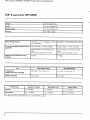
Product Information
●
Product Information
Prinh?r
Features
Features
6 PPM
Print Speed
a
Text & Graphite
~
600 dpi; plus Resolution Enhancement Technology (REt)
Resolution
Printer Lsnguages
HP LaserJet 5P
Enhanced PCL 5
Postscript Level 2’
Enhanced PCL 5
HP LsaerJet 5MP
Monthly Ueage (psgea)
up
Memory:
2MByte on-board standard memoy
Trsy 1 Capacity
100
Trey 2 Cspacity
250
Output Trey capscity
100
Internal Typefaces
HP LaserJet 5P
45 PCL
12,000
45 PCL, 35 PS
LsserJet 5MP
●
to
Standard interfaces
2 Parallel (B connector, C connector)
1 LocalTalk
1 SIR
Power Control
Power switch
NVRAM
Yes
Statua Panel
2 Buttons
5 LEDs
Economode
(toner saving)
yes
Min. Paper Size
(using flat paper path)
‘SIMM includes 1 MByte additional
3 x 5 inch
(76 x 127mm)
,
memory.
0’
3
HP LaserJet 5P Printer Service Supplement
Product Information
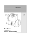
Key Printer Locations
and Parts.
Q
9
Q
9
0
A
Q
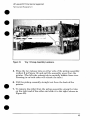
Figure 1
1.
2.
3,
4.
Front View
Status Panel
Top Output Tray
Tray 1- Multi Purpose Tray
Tray 2- 250-sheet Paper Cassette
5.
6.
7.
Infrared Port and Status Light
Removable Side Panel
Interface Cable Door
o
e
o
Q
Q
A
Figure 2
1.
2,
4
Rear View
Top Cover Release Button
Rear Output Tray
3.
4.
5.
Serial Number Label
Power Cable Door
On/Off Button
HP LaserJet 5P Printer Service Supplement
Product Information
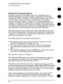
Model and Serial Numbers
The model number and serial numbers are listed on identification
labels located on the rear of the printer. The model number is
alphanumeric, such as C3 150A for the HP LaserJet 5P ~ri nter and
C3 155A for the HP LaserJet 5MP printer.
The serial number contains information about the Country of
Origin, the Revision Level, the Production Code, and production
number of the printer.
The rear labels also contain power rating and regulatory
information as shown in Figure 3.
.,-.. —...
-!,—.’— —
Illltillllllllnlllnlllnlllll
LI 0434A
FCWER Rmltm
W-.O
==~~’&5FZ7Ej
L.
Figure 3
Md 1986
,
%mpk? Mcx-kl and serial Numk)w Labels
5
HP LaserJet 5P Printer Service Supplement
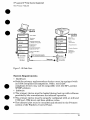
Product Specifications
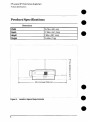
Product Specifications
Dimensions
Width
15.79 in. (401 mm)
Depth
17.38 in. (441 .7mm)
Height
7.92 in. (201.1 mm)
Weight
15,4 Ibs. (7 kg)
I
1-
39.5 inches/1
.. . .. .
Figure 4. Location $pace Requirements
6
000 mm
.
..
HP LaserJet 5P Printer Service Supplement
Product S~ecifications
Electrical S~ecifications
Power Requirements
100/1 20V (+/- 10%) 50/60Hz (+/- 2Hz)
127 Volts NOM
220/240V (+/- 10%)50
Hz (+/-
I
2Hz)
7iiiiEEE3
Power Consumption (typical for HP
LaserJet 5P and HP LaserJet 5MP)
Minimum recommended
capacity
circuit
Environmental
I
Item
Temperature
(printer and toner cartridge)
I Relative humidity
Duing printing -165 W (average)
Duing printing -165 W (average)
During standby - 5W (instant power
During standby - 5W (instant power
4 Amps
1.8 Amps
I
S~ecifications
Storage/Standby
Operating Printing
I
59”
tO 89°
F (15” to 32.5° C)
-4°
to
104° F (-20”
tO 4(1” C)
I
110%,080%
Ilo%to,o%
I
AC.CSLMC
Emissions (Per 1S0 9:296)
*In this mode, the printer is essentially
quiet.
7
HP LaserJet 5P Printer Service Supplement
Documentation and SoMware
Documentation and Software
Documentation
You can order the documents
some documents.
Table 1.
I
listed below. There is a charge for
Related Documentation
Title
The PCUPJL Technical Reference Package contains the following
documents*
I Part Number
5961-0601
PCL5 Printer Language Technical Reference Manual.
Explains the PCL 5 printer language for experienced users and
programmers.
Printer Job Language Technical Reference Manual.
Explains HP’s Printer Job Language (PJL) for experienced users
and programmers.
PCUPJL Technical Quick Reference Guide.
PCL Comparison Guide.
Describes the different implementation of commands and
extensions across the printer family supporting PJL and PCL 5.
HP LaserJet 5P/5MP Printer User’s Manual
C3150-90901
HP LaserJet 5MP Macintosh Notes* (included with HPLaserJet
5MP Printer and optional Adobe PostScript Level 2 SIMM)
C3155-90901
HP LaserJet Printer Family Paper Specification Guide*
5002-1801
* This item must be ordered through HP Parts Direct Ordering, (800) 2278164. Outside the U. S., see the ordering information in “Parts and Diagrams”
later in this chapter.
8
HP LaserJet 5P Printer Service Supplement
Documentation and Software
Software
The following software driver diskettes are shipped with the
C3150A HP LaserJet 5P printer:
The HP LaserJet 5P DOS Utilities and DOS Printer Drivers
diskette. The DOS utilities include a Status Monitor and
Remote Control Panel. The DOS printer drivers include
WordPerfect (versions 5.1, 5.1+, and 6.0) and Lotus 1-2.3
(versions 2.3,2 .4,3.1 and 3.4).
The HP LaserJet Printing Svstem for Microsoft Windows 3.1
and 3.11 contains the PCfi d“tivers ‘and the HP FontSmart
utility for font management.
The following software driver diskettes are shipped with the
C3155A HP LaserJet 5MP printer:
~ The HP LaserJet 5MP Printer Software for Macintosh.
System 6.07 to 7.5.
SUppOrtS
~ The PostScript Printer Software for Windows 3.1 and 3..11
includes the PostScript drivers and the H-P FontSmart utility
for font management.
HP LaserJet 5P Printer Service Supplement
New Product Features
New Product Features
The HP LaserJet 5P/5MP Status Panel
This HP LaserJet printer has been designed to be controlled
mainly by software. However, some simple functions are also
available from the status panel. You also receive status
information about the operation of the IrDA-compatible infrared
(IR) port from the status light just above the port (for more
information, see “To Print Using the Infrared Port,” later in this
appendix).
Figure 5
1.
2.
3.
4,
Status Panel Buttons and Lights
RESET button
ERROR status light
TRAY 1 status light
TRAY 2 status light
5.
6.
7.
8.
DATA status light
READY status light
GO button
IR port status light
The Status Panel consists of two buttons you use to complete
certain tasks and five status lights that indicate the status of the
printer (see Figure 5).
The GO and RESET Buttons
The printer has two buttons: GO and RESET.
10
HP LaserJet 5P Printer Service Supplement
New I’roduct Features
Pressing the GO button
●
●
~ Tells the printer to resume printing.
~ Prints a demo page. The printer must be in Ready Mode (the
green Ready light on steady).
Q Prints a self-test page when pressed simultaneously with the
RESET button. The printer must be in Ready Mode (the green
Ready light on steady).
Pressing the RESET button:
o
Clears
incomplete
0
clears
errors.
print jobs
from the printer’s
memory.
Q Removes all temporary fonts and macros.
Q Returns all printer settings to the default values that you
selected.
The Status Lights
There are five Status Panel lights on the printer:
~ ERROR
@ TRAY 1
Q TRAY 2
~ DATA
~ READY
●
●
These lights indicate the current status of the printer by
displaying an amber or a green hue and flashing individually
sequentially as a group (cascading).
The status light above the IR port indicates tlhe current status of
the IR port by displaying a green hue. This status light comes on
only when the IR port is being used—the Status Panel lights
operate the same for the IR port as they do for any other port on
the printer.
ERROR
●
or
(amber)
Indicates an error condition, such as a paper jam, missing l;oner
cartridge, or the printer’s top cover is open.
11
HP LaserJet 5P Printer Service Supplement
New Product Features
TRAY 1 (amber)
Tray 1 (the MP tray) is empty. Add paper to Tray 1. When the
Tray 1 light is flashing, the printer is waiting for paper to be
manually fed into Tray 1. Once you have inserted the paper, you
must press the GO button to feed the paper.
●
TRAY 2 (amber)
Tray 2 (the Paper Cassette) is empty. Add paper to Tray 2.
●
DATA (green)
When the Data light is on, the printer is printing. When the Ready
light and the Data light are both on, the printer still has unprinted
data in its memory. Either press GO to print the remaining data,
or press RESET to clear the data from the printer’s memory.
READY (green)
The printer is in Ready Mode when the Ready light is on. If the
light is flashing, the printer is currently receiving data or in the
process of printing.
IR Port Status Light (green)
If this light is on, it indicates that an infrared (IR) connection
been established.
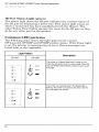
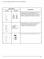
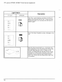
Common LED patterns
The chart following shows the light patterns for normal HP
LaserJet 5P/5MP printer states.
12
has
HP LaserJet 5P Printer Service Supplement
New Product Features
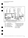
Paper Movement
Overview
The paper feed system picks print media automatically from the
paper cassette or accepts it from the manual feed slot and delivers
it to the image formation system at precisely the right time. The
system then feeds the media to the fusing station, and delivers the
finished product to the output position, either the face-down
output tray on top of the printer, or through the face-up delivery
slot at the rear of the printer. The output path is user-selectable by
opening the rear output tray.
e
●
Figure 6 shows the possible paper paths and locations of the
various solenoids, photosensors and rollers.
●
16
HP LaserJet 5P Printer Service Supplement
New Product Features
DC Controller
I
Fkwc!
Paper Cassette
6
PCA
___
.
.’
HP LaserJet 5P Printer Paper F%M
Psi
Input Paper Sensor
PS2
Tray 2 Paper Out Sensor
Input Paper !3ensor (PSI) Positions:
A = Manual Feed Sense Pcsition
PS3
Exit Paper Sensor
B = Registration Sense Position
PS4
Winding Paper Sensor
C = TOP Sense Position
PS5
Tray 1 Paper Out Sensor
SLI Tray 2 Solenoid
SL2 Tray 1 Solenoid
17
HP LaserJet 5P Printer Service Supplement
New Product Features
Infkared Communication
The HP LaserJet 5P and 5MP printers are equipped with an
Infrared Datalink Association (IrDA) compliant port. The IrDA
specification allows “wireless” transmission of print data between
a wide variety of hosts (primary) and peripheral (secondary)
devices. A primary device -- such as a PC or laptop computer -- is
capable of reading and writing data to another primary device or
writing to a secondary device, such as a printer. Secondary devices
are read-only; they cannot initiate its own communication, and can
only respond to a host command when properly addressed.
The IrDA protocol uses a transceiver chip in both devices to send
and receive data packets. The packets are checked for validity, and
a response is sent by the secondary device indicating whether the
packets were complete or in error.
The IrDA protocol is contained in three layers:
●
●
●
The physical electronics are the hardware elements in each
device for sending and receiving the data.
The Link Access Protocol (LAP) layer controls the physical
layer, packetizes/unpacketizes
data, and sets transmission
rates.
The Link Mana~ement Protocol (LMP) laver routes data to and
from the host o~erating system (DOSfii~dows).
The data flow is shown in Figure 7.
The LAY and LMP layers can reside in either firmware, software,
or a combination of both. There are different LAP and LMP
protocols for primary and secondary devices.
The HP LaserJet 5P printer has the complete secondary protocol,
and any host trying to communicate via the infrared (IR) port must
have the complete primary protocol installed. The prirmwy protocol
software is the responsibility of the host supplier. It is not provided
by Hewlett-Packard Company with the printer.
IrDA communications can be obtained either via an internal IR
port or an external IR accessory. Several manufacturers offer
complete accessory upgrades for both host and peripheral devices.
18
HP LaserJet 5P Printer Service Supplement
New Product Features
Application
ASCII
-%,
. ,
$ffji?y
sec ~e:crg
Data
El Q
GDI
DDI
Windows
System
ASCII to
Raster Data
1/0 Buffer
ASCII
Dot>
Pir DVR
Standard
U Ptinter
IRLMP
IRLMP
IR Redirector
(Software)
UnFack$
IRLAP
IR Driver Packetizes
Data (SW or FW)
IR!AP
Checks
IR Physics
Protocol
De$erla!!zer
IR Chip
IR Physical
Protocol
IR Chip
endows
Driver (SWI
Formatter
Sencwzer
s
Buffer
Data
Packets
d
Transmiitel
Figure 7’, lR Dab Flow.
System Requirements
0 ~ar~ware
. Both the primary and secondary devices must be equipped with
an IrDA-compliant IR component. Older, non-lrDAcompliant devices may not be compatible with the HP LaserJet
5P/MP printers.
~ Software
The primary device must be loaded during boot-up with software
provided by the manufacturer for infrared operation.
. The primary device must be properly configured with an infrared
COM port, IRQ level, and base address value.
● The infrared port must be installed
and selected in the Printers
section of the Windows Control Panel.
●
19
HP LaserJet 5P Printer Service Supplement
New Product Features
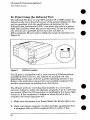
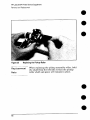
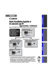
To Print Using the Infrared Port
The infrared (IR) port on your HP LaserJet 5P or 5MP printer is
located on the lower front left corner of the printer (Figure 8). This
port is compliant with the specifications de~ermined by the
infrared Data Association (IrDA). Just above the port is a status
light that indicates when the port is activated. To use the IR port,
you need to use a portable device that also includes an
IrDA-compliant IR port and be within the range of operation (see
Figure 9).
Figure 8
lrDA Port Location
The IR port is compatible with a wide variety of IrDA-cornpliant
portable devices; however, the method for printing will vary
depending on the type of device and the operating system in use.
Refer to the instruction manual for your portable equipment for
specific instructions on printing from that device.
The IR port works by receiving data similarly to a serial port,
however, without a cable and operates at speeds of up to 115 k bits
per second. When the IR connection is established, the status light
comes on. If the connection is broken or when the print j ob is
complete, the status light goes off,
1. Make sure the printer is in Ready Mode (the Ready light is on).
2. Align your laptop computer (or other portable equipment) that
is equipped with an IrDA-compliant IR port within 3 feet
20
HP LaserJet 5P Printer Service Supplement
New I’mduci Features
(1 m) of the IR port on the printer and at an angle of *1 5
degrees to ensure printing (Figure 9).
3.
Send the print job. The status light above the IR port turns on
(printing a complex document or using a software print spooler
on your PC may delay the time it takes for the IR status light to
turn on). If the status light does not turn on, realign the port on
your portable equipment with the port on the printer, resend
the print job and stay within the range of operation during
printing.
4.
If you have to move the device, for example, to add paper, make
sure you stay within the range of operation to maintain the
connection. If the connection is interrupted before your print
job is complete, the IR port status light will turn off. You have
from 3 to 40 seconds (depending on the host implementation)
to
correct the interruption and continue the job. In this case, the
IR port status light turns back on.
5.
The connection can be permanently broken (interruptec[ for
more than 3 to 40 seconds) if the “sendin< IR port is moved out
of the range of operation or if anything passes between the two
ports to b~ock the transmission, such &-a hand or piece of
paper, or even direct sunlight. In this case, the job needs to be
reprinted.
21
HP LaserJet 5P Printer Service Supplement
New Product Features
If you still have problems printing, make sure you are using an
IrDA-compliant device and proper software and have selected the
proper port for printing. See “Infrared Port Not Responding” on
page 65.
Note
The IrDA standard for infrared communications
represents an emerging technology, Older
non-IrDA-compliant
portable devices may not be
compatible with your HP LaserJet 5P/5MP
printer. If you continue to have problems
printing using the IR port, contact the
manufacturer or dealer where you purchased
your portable device to verifj compatibility with
the IrDA standard, and follow the
troubleshooting procedure immediately
following.
Troubleshooting
IR Printing Problems
IR printing problems maybe caused by any of the several system
components or by lack of proper conf@u-ation.
The following
checklist will help determine the source of the problem.
6. Verify the user is operating the printer and PC as described in
the User’s Manual: less than one meter between devices, and
not more than *15 degrees from direct center.
7. Verify the host PC or laptop and the printer are IrDA-compliant
and have the necessary hardware components for IR
communication.
8. Verify the IR software has been loaded on the primary device.
(This is system software and should be available from the PC
manufacturer. )
9. Verify the host PC or laptop is properly configured. Check the
port assignment, the IRQ level, and the base address value.
Check both the DOS AUTOEXEC.BAT
and CONFIG.SYS files,
and the Windows system configuration.
22
HP LaserJet 5P Printer Service Supplement
New Product Features
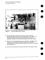
If all these elements are properly installed and configured, use the
IR test tool to test the IrDA protocol transmission and device
operation. This tool for troubleshooting IR communication
problems, shown in Figure 10, has been developed by Genoa
Technology, Inc., in cooperation with Hewlett-Packard.
The part
number is 5062-4661 and can be ordered through HP Parts Direct
Ordering.
The IR test tool can be used with any IrDA-compliant
secondary device, regardless of manufacturer.
1
(R Diodes
Test
primary or
I
cOtItIeCt
P&3SS
‘&ooo
● 0
Per+:&l
Computer
Test
Test Modes
PCL Printer
PostScript
Energy
Test
Figure :10
Wrarc!xi
Printer
Detect
Frame
Tt?st ‘TCml
To test the peripheral
device:
1. Put the HP LaserJet 5P in Ready Mode.
2. Press the “Peripheral Test” button on the test tool. The LEDs
on the test tool will sequence.
23
HP LaserJet 5P Printer Service Supplement
New Product Features
If the “PASS” LED lights, the test was successful, indicating that
communication with the printer’s IR port is functioning nor&ally.
On HP LaserJet printers, a self-test page will be initiated by the
test.
●
If the “TEST’ LED goes out and the “PASS” LED fails to light, the
printer’s IR port is not functioning correctl~ check the operator’s
instructions included with the IR test tool.
@
To test the host computer
1. Place the test tool on a table in front of the PC’s IR port
2.
Press the “Computer
the LEDs.
Test” button. The test tool will sequence
If the “PASS” LED light, the test was successful, indicating that
communication with the printer’s IR port is functioning normally,
If the “TEST’ LED goes out and the “PASS” LED fails to light, the
host’s IR port is not functioning correctly.
●
24
HP LaserJet 5P Printer Service Supplement
New Product Features
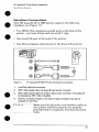
Interface Connections
●
●
Your HP LaserJet 5P or 5MP printer supports the following
interfaces (see Figure 11):
@ ho IEEE.128&omp]iant
parallel ports at the back of the
printer—one large B-type and one small C-type.
@ One LocalTalk
port at the back of the printer.
o One IrDA-compliant
~jg~~[;~j
~p
~~~gi~J~~
infrared
~p/~~~p
port
~~i[~~~f
at
the front of the prirlter.
~~@ff~f-~
~~~~~~~~~n~
1.
LocalTalk cable and connectors,
2.
IEEE-1284 parallel cable and large (B-type) printer connector.
●
3.
IEEE-1284 parallel cable and small (C-type) printer connector. (The cable will
be stamped as IEEE-I 284 compatible.
4.
Host PC connector (A-type) (in the future C-type connectors may also be
available on host PCs).
●
eaufrc)n
Make sure that all power and interface cables on
your printer and host computer are properly
grounded and in compliance with local electrical
codes.
25
HP LaserJet 5P Printer Service Supplement
New Product Features
The Parallel Printer Interfaces
These interfaces are compliant with IEEE-1284 specifications for
“Compatibility Mode” and “Nibble Mode” or “HP Bi-tronics”. To use
advanced interface functions, such as hi-directional
communication, the parallel port on your host PC must also be
IEEE-1284 “Nibble Mode” compatible.
●
The small “C” connector offers IEEE-1284 II (level 2) electrical
interfacing, i.e. support for cables up to 10 meter length. The large
“B” connector supports standard cable lengths up to 3 meters.
a
The parallel interfaces can operate at speeds of up to 2 MBytes per
second. Use a high-quality, shielded IEEE-1284 compliant parallel
interface cable to insure best performance and support of advanced
interface functions such as hi-directional communication.
Compliant cables are marked with “IEEE-1284” on the cable.
Applications such as the Remote Control Panel, Status Monitor, or
the Status Window use the printer’s parallel interface to send
status information back to the computer (hi-directional
communication). This requires a direct connection from the
computer to the printer via a local parallel port (for example,
LPT1:, LPT2:). These applications may not work through a
network or a switching device.
Connecting
to Networks
and Switchboxes
Most devices connected between the printer and the host computer
prevent the printer from sending data back to the computer.
Therefore, the Remote Control Panel, Status Monitor, and Status
Window may not work with networks, most hardware print
spoolers, some software print spoolers, and some switchboxes.
Newer sharing devices are available that fully support status
feedback. Check with your supplier on support for hi-directional
communication.
Automatic
●
I/O Switching
The printer automatically switches between all interfaces (parallel,
infrared, and LocalTalk) when multiple users share the printer.
a
●
26
HP LaserJet 5P Printer Service Supplement
New Product Features
Resource
Saving
Resource Saving gives the printer the ability to save certain
entities such as permanent soft fonts, macros, symbol sets and
user-defined graphics patterns when the printer changes
personalities, resolutions or page protect modes. For example, if a
user switches the printer from PCL mode to PostScript mode, all
PCL soft fonts and macros are lost.
With resource saving, the HP LaserJet 5P/5MlP printer can retain
these in memory. When the user switches back to PCL from
PostScript all of the PCL entities would still be resident in the HP
LaserJet 5P/5MP printer. Resource Saving can be changed via
software, but can only be accessed when the printer has the
PostScript language installed and a minimum memory
configuration of 7 MB.
Resource Saving can be set via software for one of three mocles,
AUTO (default), ON, and OFF. Auto configuration sets the
Resource Saving for PCL and Postscript to a minimum value (400
KBytes) for each personality. Setting Resource Saving to ON
allows the user to determine how much printer memory will be
used for Resource Saving for the PCL personality and the
Postscript personality. The memory can be allocated in 100 KBytes
increments. For example, if the user sets the Resource Saving
memory size to 200 KBytes, a total of 400 KBytes of memory will
be assigned to Resource Saving. 200 KBytes of memory will be
used for Postscript Resource Saving and 200 KBytes of mern.ory
will be used for PCL Resource Saving. Turning Resource Sating
OFF disables the Resource Saving fbnction and no memory is
allocated to Resource Saving.
27
HP LaserJet 5P Printer Service Supplement
New Product Features
I/O Buffering
I/O buffering allows the user to allocate printer memory to hold
the job while it prints, freeing up the host system sooner, like a
print spooler. The standard printer has approximately 10 KBytes
of memory allocated to I/O buffering and an additional 100 IIBytes
of memory is assigned to I/O buffering for each MBytes of memory
added to the printer.
If the printer has a minimum of 6 MBytes of memory installed, the
I/O buffer size can also be adjusted via software. Three settings
exist for the 170 buffer; AUTO (default), ON, and OFF. AUTO sets
the printer’s 1/0 buffer to a minimum value that is determined by
the total amount of memory that is resident in the printer. Setting
I/O buffering to ON allows the user to set the 1/0 buffer size
Setting the I/O buffering to OFF disables )70 buffering.
Note
28
When you change the I/O buffer setting all
downloaded resources are deleted.
●
●
HP LaserJet 5P Printer Service Supplement
New Product Features
THIS PAGE INTENTIONALLY
LEFT BLANK
●
29
HP LaserJet 5P Printer Service Supplement
Service Mode, PJL Defaults
Service Mode, PJL Defaults
The Service Mode should be used only by authorized
personnel. While in Service Mode, you can:
service
●
Print a Service Mode Self Test.
●
Verify and set the Page Count (the page count also is displayed
on the standard self test).
●
Set the Cold Reset Default. (This sets the factory default paper
size to either Letter or A4).
●
Set the Demo Page=True/False.
Used to remove the Demo Page
option from the self test menu.
Set the Diagnostic Functions ON or OFF (for software
developers ;se only).
●
●
Since the HP LaserJet 5P/5MP printer does not have a front
control panel, Service Mode and many configuration tasks are
accessible only through software (PJL commands).
The following example shows how to use PJL commands to enter
Service Mode and perform various Service Mode configuration
tasks.
Note
Text is CASE-sensitive in PJL; enter exactly as
shown. The EC symbol stands for the ASCII
escape character (ESC or /027). When the PJL
code is entered, print the data file (or use the
DOS COPY command to copy it to the printer).
Detailed explanations of PJL commands and their functions can be
found in the Printer Job Larwuage Technical Reference Manual
(HP part number 5961-0704~
-
30
●
HP LaserJet 5P Printer Service Supplement
Service Mode, PJL Defaults
CkwmK9n PJL commands
~=xp’anation
Mode
@PJL SET SERVICEMODE=HPBOISEID
Enter Service
@PJL SET PAGES=O
Set page count [= xxxxx]
@PJL SET CRPAPER=LETTER
Sets cold reset page size [= Letter/A4]
@PJL SET SKIPDEMO=FALSE
Skips demo/PCL type page [= true/false]
@PJL SET DIAGNOSTICS=OFF
Sets diagnostics [= OFF/ON] (fol’ ISV use)
@PJL SET SERVICEMODE=EXIT
Exits Service Mode
@PJL DEFAULT PAPER= LETTER
Selects user paper size default
@PJL RESET
Performs PJL reset
Ec%-1 2345X
Exits PJL mode
ECZ
Prints Self-Test page
ECE
Resets the printer.
Other PJL Command examples:
@PJL INITIALIZE
Sets user environment to factory defaults.
@PJL SET ECONOMODE=ON
Sets Economode
@PJL SET PAGEPROTECT=LEGAL
Sets the memory size for page protection
to LEGAL paper size.
@PJL SET MANUALFEED=ON
Sets manual feed mode.
@PJL SET LANG=
Sets the default display languagel
FRENCH,
1 Do not confuse this command with @PJL ENTER LANGUAGE,
the printer language to PCL or PostScript.
which sets
31
HP LaserJet 5P Printer Service Supplement
Service Mode, PJL Defaults
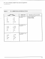
Test Pages and Resets
Test pages, resets, and NVRAM initialization can all be performed
by using the GO and RESET buttons on the HP LaserJet 5P/5MP
printer status panel. Table 2 shows how to perform these tests and
diagnostic functions.
Table 2.
FUNCTION
Button Functions
ACTION
I
RESULT
Self Test
Press GO and RESET buttons
simultaneously.
Prints a Self Test page.
Continuous
Self Test
Hold GO button more than 20
seconds after powering on
pinter
Prints continuous self test
pages. Press the button to stop
printing.
Reset (all 1/0)
Press RESET button.
Clears ail data from memory,
including unprinted data,
downloaded fonts and macros.
rF
Continue
Cold Reset
I
Allows the printer to recover and
(Waiting for paper, or
continuable error.) Press the GO continue printing the job.
Press the GO button,
Hold RESET button less than 20 Clears all data from memory,
seconds after turning power on. including unprinted data,
downloaded fonts and macros.
Resets printer to factory default
NVRAM
Initialization
Hold RESET button more than
20 seconds after turning power
on.
Service Error
Codes
Press GO and RESET buttons
to display additional code.
32
lPrint remaining data imprinter
Clears all 1/0 and print
configuration information from
NVRAM.
See “Troubleshooting” to
determine the problem and
I solution.
HP LaserJet 5P Printer Service Supplement
Service Mode, PJL Defaults
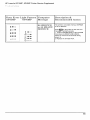
Printing a Self-Test Page
You can print a self-test page to get information about your
printe~s current settings, options, and print quality. You can use
this page to troubleshoot print quality problems and to view
current print density and Resolution Enhancement settings so you
can adjust them.
You can also print the demo, or demonstration,
check that the printer is operational.
page to quickly
To print a self-test page:
Simultaneously press the GO and RESET buttons on the printer’s
Status Panel while the printer is in Ready Mod[e.
Or using the HP LaserJet PCL Windows Printer Driver, unc[er
“Device Option”, select the “Configure Printer” button and choose
“PCL Self-Test Page”.
Or using the Remote Control Panel (in DOS], under “Options”
select “Print Test Page” and choose “PCL Self-Test Page”.
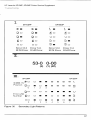
Figure 12 shows a sample self-test page. Numbers in the sample
self-test page match numbers in the Key to Figure 12, which
follows the illustration. The appearance of the self-test page vanes
depending on the options currently installed in your printer.
Note
The factory default for the self-test page is
English. A PJL command is required to change
the self-test language to appear in a language
other than English. Refer to the discussion of
PJL commands on page 31
33
HP LaserJet 5P Printer Service Supplement
Service Mode, PJL Defaults
Gb[
T!%
I ‘“-----”
Figure 12. HP LaserJet 5P Self-Test Page
34
HP LaserJet 5P Printer Service Supplement
Servir;e Mode, PJL Defaults
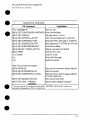
Keyto Figure12. self-l-w
Item I
Page
Explanation
1
Printer Options: Ustspfinter options youcanadjust
“Software Procedures”).
using yourptinter soMare(see
Appenclix F,
2
Test Pages: Shows testpages youcanptint
3
PCLMemory information:
available memory for PGL
4
LocalTalk Name/Node ID/Network Number: lfyourptinter isconnected toa LocalTalk nefwork, shows
the network name, node ID for your ptinter, and the network number.
fromyourprinter,
Shows thetotal amount ofinstalled memoW. Alsoindcates
theamountof
applications.
1
5
Formatter Number:
6
RAMsize:
7
Page Count:
8
Ffrmware Datecode:
Shows setialnumber
ofinternal e[ectronlcsboard,
Shows total installed printer memory,
Shows number ofpagesthe
printer hasprinted.
Eight-dgit date (YYYYMMDD) of formatter fimjware.
Resolution Enhancementi When resolution issetto 600dpi, the Rf?solution Enhancement t,?chnology
(REt) block appears here. The REt block illustrates current resolution enhancement (see “Hne-Tuning Print
Quaky,” in Chapter 2, “Printing”).
+-
l/O Buffering and Resource Saving: information about thecurrent configuration appears here.lfthe
ptinter does not have enough memory installed to enable l/O Buffeting or Resource Saving, the amount of
addtional memory needed appears here,
11
Print Pattern:
Illustrates print density andquality
12
Insfailed Peraonafities:
Shows which printer languages (personalities) are installed.
35
HP LaserJet 5P Printer Service Supplement
Life Expectancy of Consumables
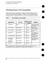
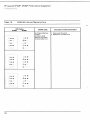
Life Expectancy of Consumables
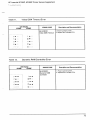
Always inspect the components listed in the following table for
wear when servicing the printer. Replace these components as
needed, based on printer failures or wear, not strictly on usage.
Table 3.
Life Expectancy of Consumables
PART NO.
DESCRIPTION
QTY EST. LIFE
(pages)
REMARKS
1.
Toner Cartridge
C3903A
1
40001
When print becomes faint,
shake cartridge to diatributa
remaining toner.
2.
Tray 1 Pickup Roller
RG5-2205-OOOCN
1
100,000
Replace roller and
separation pad together.
s.
Tray 2 Pickup Roller
RBI-6332-OOOCN
1
100,000
Look for glazing end
cracks.
4.,
swara~onPad
RF5.0343-OOOCN
1
100,000
Look for glazing and
groovas. Replace together
with Pickup Roller.
s.
Transfer Charging Roller
RF5-I 287-OOOCN
1
100,000
May affecl print quality
and/or paper jams
6.
Fuser Assembly
(115 V, 50/60 Hz)
RG5-I 700-OOOCN
1
100,000
May affect print quality
and/or paper jams. Look for
marks on rollers.
Fuser Assembly
(220 V, 50 Hz)
RG5-1701-OOOCN
1
100,000
Exhaust Fan
RG5-I
1
25,000 hrs.
7-
801-OOOCN
‘The estimated Toner Cartridge life is based on A4 or letter eize prints with
an average of 570 toner coverage, and with the density setting at 3.
36
HP LaserJet 5P Printer Service Supplement
Removal and Replacement
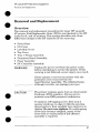
Removal and Replacement
Overview
The removal and replacement procedures for many HP LaserJet
5P printer Field Replaceable Units (FRUS) are identical to the HP
LaserJet 4L and 4P printers. This section describes only those
differences unique to the HP LaserJet 5P for removing:
Power Door
1/0 Cover
Left Side Cover
Top Cover
Tray 1 Pickup Assembly
Formatter Board Assembly
Fuser Assembly
DC Controller Assembly
WARNING!
Unplug the power cord from the power outlet
before attempting to service the printer. If this
warning is not followed, severe injury may result.
Never operate or service the printer with the
protective cover removed from the
Laser/Scanner Assembly. The reflected beam,
although invisible, can darnage your eyes.
CAUTION
The printer contains parts that are electrostatic
discharge (ESD) sensitive. Always service
printers at an ESD protected workstation.
To install a self-tapping screw, first turn it
counter-clockwise
to align it with the existing
thread pattern, then carefully turn clockwise to
tighten. Do not over-tighten. If a self-tapping
screw-hole becomes stripped, repair of the
screw-hole or replacement of the affected
assembly is required.
37
HP LaserJet 5P Printer Service Supplement
Removal and Replacement
Note
Always remove the toner cartridge and the
paper cassette from the printer before removing
or replacing printer parts.
●
Required Tools
Refer to page 6-3 of the Combined
A TORX T-10 head screwdriver
shield.
Service Manual.
@
is needed to remove the formatter
o
38
HP LaserJet 5P Printer Service Supplement
Removal and Replacement
Removing
the Power Door
The Power Door is located on the right rear of the printer.
1. Ensure the power to the printer is turned OFF.
2. Grasp the power door by the finger slot directly above the
power cord, and swing the rear of the door out and forward.
The door easily tilts and lifts out.
3. Unplug the power cord from the printer power socket.
Removing
the 1/0 Cover
The 170 Cover is located to the left rear of the printer.
1. Locate the two release tabs shown in Figure 13.
Press the tabs
39
HP LaserJet 5P Printer Service Supplement
Removal and Replacement
Removing
the Left Side Cover
1. Disconnect
all I/O cables.
2.
Press the Top Cover Release button on the right side of the
printer, and open the top cover.
3.
Press the removable
Figure 14.
4.
Slide the cover forward and pull straight away from the side of
40
side panel release latch shown in
HP LaserJet 5P Printer Service Supplement
Removal and Replacement
Removing
the Top Cover
1. Remove the toner cartridge and paper cassette if they have not
:.-.:>
~,:
/
Figure 15
Removing the Top Cover Screws
3. Grasp the lower left front corner of the top cover, and lift it
forward and up.
4. Grasp the lower portion of the right front cover, and pull
forward and up.
5. At the rear of the printer, lower the face-up output tray.
—
41
HP LaserJet 5P Printer Service Supplement
Removal and Replacement
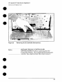
6. Lift the rear of the printer slightly. Grasp the lower right back
corner. With your thumbs, flex the plastic toward you, up, and
out. Figure 16 shows this process for the rear right corner.
Repeat the process for the left rear corner.
—
Note
Note the position of the tabs and the catches
carefully. This step may require considerable
twisting and flexing of the plastic in order to free
the release tabs.
●
●
—
Figure 16
Releasing the Back Corner of the Top Cover.
●
7. Lift the printer cover straight up.
●
42
HP LaserJet 5P Printer Service Supplement
Removal and Replacement
When reseating the top cover onto the p:rinter
frame, ensure the black paper-out flag in front
of Tray 1 is seated in the groove of the Tray 1 lift
plate. If not in the groove, it can easily break
when the cover is forced into place. Refer to
Figure 17
43
HP LaserJet 5P Printer Service Supplement
Removal and Replacement
Removing
the Tray 1 Pickup Assembly
1. Remove Tray 1 by opening the tray at a 45° angle and pulling
up on the tray (Figure 18).
Figure 18
Removing Tray 1.
2.
Urmhw the two cables (Callout 2 in Fi~re 19) by grasping the
cables ‘where they attach to the plug a-ridpulling straight back.
3.
Route the cables through the right side of the printer chassis
and bring them to the front.
4.
Remove the 5 screws (callout 1 in Figure 19) from the front of
the pickup assembly. (TWO screws are adjacent in the lower left
corner.)
44
HP LaserJet 5P Printer Service Supplement
Removal and Redacement
Figure 19
Tray 1 Pickup Assembly
Locations,
!5. Press the two release tabs on either side o:f the pickup assembly
(callout 3 in Figure 19) and pull the assembly away from the
view.
printer. (The left side release tab is partially hidden hom
Pressing in on both sides will release the tabs.)
6. Pull the pickup assembly straight out from the back of the
printer.
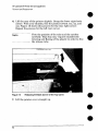
7. To remove the roller from the pickup assembly, grasp the tabs
on the right end of the roller and slide it to th~ ‘~ght’(shown
Figure 20).
in
45
HP LaserJet 5P Printer Service Supplement
Removal and Replacement
Figure
20
Replacement
Note
46
Replacing the Pickup Roller
When replacing the pickup assembly roller, hold
the shaft from the left side so that the pickup
roller shaft and gears will remain in place.
HP LaserJet 5P Printer Service Supplement
Removal and Replacement
Removing
●
the Formatter Board and Shield
1. Remove any installed SIMMS.
Nott?
a
There are two TORX screws holding the 1/0
connector in ~osition (Callout 1 in Figure 21).
These are th~ only two TORX screws-in the HP
LaserJet 5P printer. Note also the location of
the test print button hole (Callout 2) on the side
of the formatter board cover.
.—
Figure 21
TORX Screw Locations.
47
HP LaserJet 5P Printer Service Supplement
Removal and Replacement
Figure 22
Removing the formatter screws.
2. Remove the (7) screws shown in Figure 22.
3. Pull the formatter board straight from the side of the chassis.
(There will be a slight resistance
interconnect. )
from the DC Controller
4. Pull the DC controller interconnect
out (Figure 23).
5. To separate the formatter PCA from its shield, remove the two
screws (refer to callout 1 in Figure 21).
48
HP LaserJet 5P Printer Service Supplement
Removal and Replacement
Figure 23
NO16?
Removing Me DC Contrcdler Interconnect.
RETAIN THE DC CONTROLLER
INTERCONNECT
when replacing the DC
Controller Board. The replacement board part
number does not include this interconnect.
49
HP LaserJet 5P Printer Service Supplement
Removal and Replacement
Removing
the Fusing Assembly
1. Remove the top cover assemblies.
2. Locate the black plastic fuser cover at the back of the printer.
Press the release tab (callout 1 in Figure 24).
3. Slide the cover all the way to the right.
4. Pull the left end of the strip toward you at a 45° angle.
5. Slide the cover to the left and out of the printer.
6. Remove the four screws (2 self-tapping
screws, two machine
screws with washers) directly below the fuser assembly.
7. Grasp the fuser by the green plastic handle and pull out from
the printer.
‘Figure 24
50
Removing the fuser cover.
a
HP LaserJet 5P Printer Service Supplement
Removal and Replacement
Removing
the DC Controller Assemblies
The DC Controller Assembly is located on the bottom of th e
printer. The PCA is protected by a metal shield assembly, and is
mounted to a plastic base. The Formatter PCA and Fusin,g
Assemblies are connected directly into the DC Controller and must
be removed prior to removal of the DC Controller Assembl y.
Cauiiai’1
Failure to remove these components befme
removing the DC Controller will result in
printer ~amage.
1. Remove the printer covers (page 39), Formatter
(page 48), and Fusing Assemblies (page 50).
2.
PCA and Shield
On the right side, remove the machine screw and washer
(Figure 25) holding the grounding spring in place. (Callout 1 in
Figure 25).
3. Disconnect the two cables to the tray 1 assembly (callout 2 in
Figure 25).
●
51
HP LaserJet 5P Printer Service Supplement
Removal and Replacement
,
I
Figure 25
4.
Grounding Spring screw location.
On the left side, remove the (2) screws that attach the
grounding strap to the Gear Train Assembly (see callout 1 in
Figure 6-36 of the Combined Service Manual). Turn the
assembly upside-down before proceeding with further steps.
5. Remove the (5) self-tapping screws and the (1) machine screw
with star washer from the bottom of the DC Controller
Assembly. (See callouts 2 and 3 in Figure 6-36 in the Combined
Service Manual.)
6. Lift the DC Controller Assembly
52
away from the printer frame.
HP LaserJet 5P Printer Service Supplement
Removal and Replacement
The PS1 Input Sensor Arm may come loose and
fall out when you remove the DC Controller
Assembly. See Figure 6-51 in the Combined
Service Manual for re-installation.
7. Remove the metal backing plate from the DC Controller
Assembly (see pages 6-43-and 6-44 in the Combined
Manual for this procedure.)
Service
8. Disconnect Tray 1 Interconnect
PCA (callout 2 in Figure 26)
and cable 302 (callout 1 in Fimwe 26) from the DC Controller
PCA.
Remove the Tray 1 Interconnect PCA carefully;
it can easily be broken when separating it from
the black plastic cover.
Note
The Tray 1 Interconnect PCA and cable must
also be retained when replacing the DC
Controller Board. The part number for the DC
Controller Board does not include a replacement
PCA and cable. This cable can be directly pulled
from the connector no releases are necessary.
53
HP LaserJet 5P Printer Service Supplement
Removal and Replacement
Figure 26
Tray 1 Interconnect
PCA and Cable 302
a
a
54
HP LaserJet 5P Printer Service Supplement
Troubleshooting
Infrared Port Not Responding
Situation
[he connection cannot be established or the transmission seems
o be taking longer than usual.
Solution
Make sure the device you are using is lrDAcompliant; look for an lrDA symbol on the
device or refer to the manual for the device for
kDA specifications.
Make sure that the operating system on your
computer includes arl IR driver and yol.u
application uses a HP LaserJet 5P/5MP
compatible printer driver.
Make sure you have positioned the device
within the range of operation and that no
objects, such as a finger, paper, books, or
bright light, are interff?ring with the connection.
Also make sure the two IR ports are clean (free
from dirt and grease).
Bright light of any kind (sunlight, incandescent
light, fluorescent light, or light from an nfrared
remote control, such as those used for TVs and
VCRs) shining directly into one of the IR ports
may cause interference.
Position the device closer to the IR poll on the
printer.
[he printer prints only part of a
)age or document.
The connection has been broken during
transmission. If you move the portable device
during transmission, the connection can be
broken. kDA-compliant devices are designed to
recover from temporary connection
interruptions. Re-establish the connection
(depending on the device you are using, you
can have anywhere from 3 to 40 seconds to reestablish the connection).
65
HP LaserJet 5P Printer Service Supplement
,,,
,.
Solution
Situation
The print job has been properly
sent to the printer, but the printer
will not print,
If the connection is broken before the entire
print job has been transmitted to the printer
(printing has not yet started), the printer may
not print any of the job, If the Data light is on,
press the RESET button to clear the printer’s
memory. Then, position the device within the
range of operation, and print the job again.
The IR status light turns off during
transmission.
The connection may have been broken. If the
Data light is on, press the RESET button to
clear the printer’s memory, Then, position the
device within the range of operation, and print
the job again.
Using the Infrared Test Tool
A special infrared troubleshooting test tool manufactured by
Genoa Technology, Inc. in cooperation with Hewlett-Packard is
available through HP Direct Ordering (part number 5062-4461).
Refer to the discussion beginning on page 22 for more information.
66
HP LaserJet 5P Printer Service Supplement
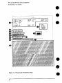
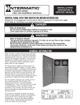
Troubleshooting
1/0
=00000=
lUEM: rEml
L-–--,
FORMAITER
=W
PCA
~
MEMORY
I
II
.,
l_l
1
-
.-
—--1--,
w
1,-
r————
I 11111
r
Ill
1111
T,,” 1
Wil
Figure 28
Main Wiring Diagram
67
HP LaserJet 5P Printer Service Supplement
Parts and Diagrams
Parts and Diagrams
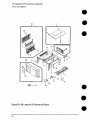
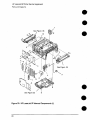
The figures in this section illustrate the major subassemblies in
the printer and their component parts. A table (material list)
follows each exploded assembly diagram. Each table lists the
reference designator (item number) for each part, the associated
part number for the item, the quantity, and a description of the
part.
While looking for a part number, pay careful attention to the
voltage listed in the description column to ensure that the part
number selected is for the correct model of printer.
Ordering Parts
All standard part numbers listed are stocked and may be ordered
from HP’s Parts Direct Ordering, or Parts Center Europe (PCE).
Hewlett-Packard
Co.
Support Materials Organization
8050 Foothills Blvd.
Roseville, CA 95678
Parts Direct Ordering:
1-800-227-8164
(U.S. Only)
Hewlett-Packard
Co.
Parts Center, Europe
Wolf -Hirth Strasse 33
D-7030 Boeblingen,
Germany
(49 7031) 14-2253
Contact your local HP Parts Coordinator
numbers.
68
for other local phone
HP LaserJet 5P Printer Service Supplement
Parts ;and Diagrams
Ordering Consumables
●
Consumables and accessories such as those listed on page 8-5, and
in Table 4-1, Chapter 4, maybe ordered direct fkom
Hewlett-Packard.
The phone numbers are:
U. S.: 1-800-538-8787
Canada:
1-800-387-3154
(Toronto) 416-671-8383
United Kingdom: 0734-441212
Germany:
0130-3322
Contact your local HP Parts Coordinator
numbers.
NC)!(?
for other local phone
Parts that have no reference designator cm-part
number are not field replaceable parts aad
cannot be ordered through SMO.
69
HP LaserJet 5P Printer Sewice Supplement
Parts and Diagrams
19
I
-
18
K&3-l,
13
Figure 29. HP LaserJet 5P Covers and Doors
70
HP LaserJet 5P Printer Service Supplement
Parts and Diagrams
●
●
●
●
Table 12.
Covers and Doors
DESCRIPTION
REF
PART NO.
QTY
1
RG5-I 709-OOOCN
1
Top Door Assembly
2
RG5-1699-OOOCN
1
Power Connector Cover ASSY
3
RBI -5931 -OOOCN
1
Cover, Main
4
RB1 -5935-OOOCN
1
Button, Lock
5
RS5-2228-OOOCN
1
Spring, Compression
Guide, Lock Button
6
RBI -5936-OOOCN
1
7
RG5-1697-OOOCN
1
Paper Feed Tray Assembly
8
RBI-5939-OOOCN
1
Arm, Tray 1 Sensor
9
C31 50-00004
C31 55-00001
1
Nameplate (HP LaserJet 5P)
Nameplate (HP LaserJet 5MP)
10
RS5-2418-OOOCN
1
Spring, “Torsion
11
RBI-5937-OOOCN
1
Stopper, Hinge, Right
12
RBI -5938-OOOCN
1
Stopper, Hinge, Left
13
RS5-2419-OOOCN
1
Spring, Torsion
14
RF5-0593-OOOCN
1
Brush, Mirror
15
RBI-5934-OOOCN
1
Cover, Interface Connector
16
RG5-171 O-OOOCN
1
Side Cover Assembly
17
RB1-5927-OOOCN
1
Bushing
18
RB1-5924-OOOCN
1
Tray, Sub-assy, Face-Up
19
RG5-1707-OOOCN
1
Face-Up Tray Assembly
71
HP LaserJet 5P Printer Service Supplement
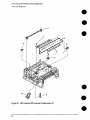
Parts and Diagrams
1
See Figure 33
4
Figure 30. HP LaserJet 5P Internal Components
72
(1)
HP LaserJet 5P Printer Service Supplement
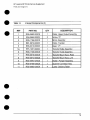
Parts and Diagrams
Table 13.
Internal Components
(1)
PART NO,
1
RG5-I 801 -OOOCN
1
Fan Assembly
2
RB1-6006-OOOCN
1
Arm, Sensor
3
RB1 -6332-OOOCN
1
M
4
RG5-1692-OOOCN
5
RG5-1799-OOOCN
1
MAssv
(tray 2)
Motor A:jsembly
6
C3150-00005
1
Formath?r Shield
7
C3152-69001
1
Postscript SIMM (exch.)
8
C3151 -67901
C3151 -69001
1
Formatt{?r PCA (new)
Formatt~?r PCA (exch,)
9
0515-2701
2
TORX screws
1
Leaf Spring
10
RBI -5971 -OOOCN
I
DESCRIPTIONI
REF
QTY
Roller (fray 2)
11
RG5-171 3-OOOCN
1
Gear train Assembly
12
RBI-5999-OOOCN
1
Plate, Groundino, Left
13
RBI-5998-OOOCN
1
Plate, Grounding, Right
73
HP LaserJet 5P Printer Service Supplement
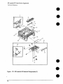
Parts and Diagrams
Figure 31. HP LaserJet 5P Internal Components (2)
74
HP LaserJet 5P Printer Service Supplement
Park and Diagrams
●
InternalComponents
Table 14.
REF
I
PART NO.
(2)
I
QTY
DESCRIPTION
I
1
RG5-0683-020CN
1
Roller, Upper Output Assembly
2
XA9-0666-OOOCN
2
Screw, TP
3
RG5-I 786-OOOCN
1
Mirror Assembly
4
RB1-5873-OOOCN
1
Roller, Transfer
5
RS5-0313-OOOCN
1
Gear,”1 7T
5a
RF5-1287-OOOCN
1
Transf~?r Roller Assembly
6
RG5-1706-OOOCN
1
Transff?r Guide Assemb~
7
RG5-0675-OOOCN
1
Transf[?r Mount Assy, Riqht
8
RG5-0674-OOOCN
1
Transft?r Mount Assy, Left
9
RG5-0694-020CN
1
Switch, Plunger Assembly
10
RG5-0766-030CN
1
Scanner Connector Assy
11
RG5-0682-030CN
4
Lower Delivery Roller
75
HP LaserJet 5P Printer Service Supplement
Parts and Diagrams
Figure -32.
76
HP LaserJet 5P Internal Components
(3)
HP LaserJet 5P Printer Service Supplement
Parts and Diagrams
●
Internal
Table 15.
I
REF
I
(3)
Ccwmpw-lenki
PART NO.
1
RG5-1780-OOOCN
C31 50-69005
I
QTY
I
DESCRIPTION
I
1
Laser Scanner Assembly (new)
Laser Scanner Assembly (exch.)
2
RG5-1698-OOOCN
1
TOP Oblique
3
RBI-3002-040CN
1
Plunger
4
RS5-2232-OOOCN
1
Spring, Compression
Roller Assy
Lock, Door
5
RB1 -6003-OOOCN
1
Plate, Cartridge
6
RBI -6002-OOOCN
1
Plate, Cartridge
7
RF5-I 286-OOOCN
1
Plate, MP Grounding,
8
RBI -6001 -OOOCN
1
Arm, Input Paper Sensor
Grounding
Right
9
RBI -2987-020CN
1
Shield, HVT
10
RG5-0584-OOOCN
1
Feeder Guide Assembly
11
RF5-1283-OOOCN
1
Eliminator, Static CharG[?
12
RG5-I814-OOOCN
1
Roller Assembly, Small Media
13
RBI-6007-OOOCN
4
Foot, Chassis
14
RBI-6008-OOOCN
6
Damper, Rubber
15
RBI -3681 -OOOCN
1
Cap, Laser Shutter
77
HP LaserJet 5P Printer Service Supplement
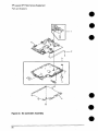
Parts and Diagrams
Flow
—1
—2
I
I
C@
/’”.
,0
@
Figure 33. DC Controller Assembly
78
/“
.
\,
HP LaserJet 5P Printer Service Supplement
Parts arid Diagrams
Table “16.
DC Controller Assembly
REF
PART NO.
QTY
DESCRIPTION
1
RG5-I719-OOOCN
1
HVT Controller Assembly
2
RH2-5259-OOOCN
1
Cable, Flat
3
RG5-171 2-OOOCN
1
DC Controller Case Assy
4
RG5-I 808-OOOCN
1
Tray 1 Connector PCA Assy
5
RBI -5987-OOOCN
1
Shield, Case
1
DC Controller
(new)
(exchange)
PCA (1 OCI-I20V)
RG5-1798-OOOCN
C3150-69001
DC Controller
PCA (220-240V)
RG5-1809-OOOCN
C31 50-69002
(new)
(exchange)
6
79
HP LaserJet 5P Printer Service Supplement
Parts and Diagrams
A
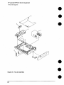
Figure 34, Tray 2 Assembly
80
HP LaserJet 5P Printer Service Supplement
Parts and Diagrams
Table “17’.
Tray2 Assembly
REF
PART NO.
QTY
R75-4000-OOOCN
1
Complete Tray 2 Assemol
RF5-0673-OOOCN
1
Plate, Side
1
DESCRIPTION
2
RS5-2458-OOOCN
1
Spring, Compression
3
RBI-3426-OOOCN
1
Claw, Separation
4
RB1-6378-OOOCN
1
Tray, Legal
5
RBI-3338-OOOCN
1
Plate, E%d
3
81
HP LaserJet 5P Printer Service Supplement
Parts and Diagrams
\
&’
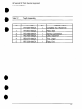
Figure 35. Tray 1 Assembly
82
/’
HP LaserJet 5P Printer Service Supplement
Parts and Diagrams
●
-r?dbk? 18,
REF
a
Tray 1 Assembly
DESC
PART NO.
QTY
RG5-I 695-OOOCN
1
Complete Tray 1 Pickup Ass
1
RG5-I 804-OOOCN
1
Tray 1 Sensor Cable
2
RG5-1694-OOOCN
1
Paper guide Plate Ass
3
RS5-2415-OOOCN
1
Sprina, Compression
4
RH7-1258-OOOCN
1
Solenoid SL2
5
RG5-1693-OOOCN
1
Tray 1 F)ickup Roller Ass
6
RBI -2205-OOOCN
1
Roller, Tray 1 Picku
7
RF5-0343-OOOCN
1
Pad, Se~aration
8
WG8-521O-OOOCN
1
Photosensor
PS5
s
83
HP LaserJet 5P Printer Service Supplement
Parts and Diagrams
@
●
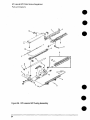
Figure 36. HP LaserJet 5P Fusing Assembly
●
84
HP LaserJet 5P Printer Service Supplement
Parts and Diagrams
●
‘-ram? 19.
REF
FM-Q
Assembly
PART NO.
DESCRIPTION
QTY
1
Complete FuserAssy(100-120V)
(new)
(exchange)
1
Complete Fuser Assy (’220-240V)
(new)
RG5-I 700-OOOCN
C31 50-69003
RG5-1 701 -OOOCN
C3150-69004
1
RBI -5918-OOOCN
1
(.f@2Ne)
Cover, Delivery
2
RBI -3097-OOOCN
1
Flao, Exit Sensor
RG5-0681-OOOCN
4
Fuser Delivery Assembly
RG5-I813-OOOCN
1
Guide, Fuser Entrance
5
XB2-8300-809CN
2
Screw, VV/Star, M3X8
6
RS5-2421-OOOCN
1
Sprinq, Tension
7
RS5-0637-OOOCN
1
Gear, 24T
8
9
RB1 -3109-OOOCN
1
Rubber, Continuity
RS5-2421-OOOCN
1
Spring, Fuser Hook
10
RB1 -591 O-OOOCN
1
Roller, Fuser Pressure
11
RG5-1702-OOOCN
RG5-I 703-OOOCN
1
Fuser Film Assembly (100-1 20v)
Fuser Film Assembly (220-240V)
12
RBI -5917-OOOCN
1
Roller, Fuser Delivery
RB1-5906-OOOCN
1
Tab, Fuser Release
3
d
13
85
HP LaserJet 5P Printer Service Supplement
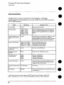
Accessories
Accessories
Listed below are the accessories and supplies, including
supplemental documentation you can order for your HP LaserJet
5P or 5MP printer.
Pari Number
Option
Toner Cartridge
Memory upgrades
C3903A
1 MByte-C3130A
~2 MByte-C3131A
4 MByte-C3132A
8 MByte-C3133A
t6MByte-C3148A
Descriptionor Use
Replacement toner cartridge.
Adds up to 48 MBytes of memory to the HP LaserJet 5P
printer, for a total of 50 MBytes. Adds up to 32 MBytee of
memory to the HP LaserJet 5MP printer, for a total of 35
MByles.
Adobe’s PostScript Level 2
SIMM for the HP LaserJet
5P
C3152A
Adds PostScript Level 2 language and 1 MByte of memory
to the HP LaserJet 5P printer includes software for
Macintosh, VVindowe 3.1 and 3.1 t, and “HP LaserJet 5MP
Macintosh Notes” (factory-installed in the 5MP printer).
IEEE-1284 Parallel Cable
2 Meter A to B-C2950A
3 Meter A to e-C2951A
3 Meter A to C-C2946A
10 Meter A to CGC2947A
lEEE-t 284-compliant cables, where:
A=host computer connector (A-type)
B=large prhrter connector (B-type)
C=small printer connector (C-type)
LocalTalk Network cable
for Macintosh
92215N
Connect to a LocalTalk Network.
Serial printer cable for
Macintosh
922t
HP JetDirect EX ptint
servers (external)
J2382B
J2383B
J2593A
J2594A
Ethernet (1 parallel ports)
TokenRing (1 parallel ports)
Ethernet (3 parallel ports)
TokenRing (3 parallel fMrts)
HP Printer Pal (externel)
C2971 A
Printer fax aueeeory. Allows faxes to be printed by the
printer; faxes can also be sent electronically from the PC.
AvailabWy outside the US may vary.
Extra Paper Cassette (Tray
2)’
R75-4000-OOOCN
Universal tray.
lrDA Test Tool
5062-4661
Infrared communications test tool manufactured by Genoa
Technologies, Inc.
5s
Directly connect to a Macintosh computer.
* This item must be ordered through HP Parts Direct Ordering, (800) 2278164. Outside the U. S., eee “Parts and Diagrams earlier in this appendix.
86
Index
DC controller 78
fusing assembly 84
internal components
printer parts 4
tray 1 assembly 82
tray 2 assembly 80
wiring 67
DMO 69
documentation
8-9
drivers 9
20 MEM OVERFLOW
56
21 PRINT OVERRUN
56
22 IO ERROR 56
40 ERROR 57
41 ERROR 57
50 FUSER ERROR 60
51 ERROR 57
52 ERROR 57
55 ERROR 57
57/58 MOTOR ERROR 61
61.x SIMM ERROR 62
62 MEMORY ERROR 63
62.x SIMM ERROR 62
63 MEMORY ERROR 63
64 ERROR 64
64 SCANNER ERROR 63
65 ERROR 64
68 SERVICE ERROR 57
M
Economode
3
erasing memory with RESET
error
clearing with RESET 11
continuable
56
data 14
fatal
15,60
hardware-related
infrared
65
A
accessories
86
automatic I/O switching
26
B
hi-directional communication
books available 8-9
buttons
GO 10
power 4
RESET 10
status panel 10
26
11
11
IR port 15
light patterns 56
memory 58
14
recoverable
secondary 56
service 60
SIMM .14,58
error light 11, 14
F
c
cables
IEEE-1284 compliant 26
clearing memory with RESET
cold reset 30
connections
network 26
consumables
life 36
ordering 69
72, 74, 76
10
D
data light 12
DC controller 78
interconnect
49
removal and replacement
51
default settings, returning to 11
demo page 10,30,33
diagnostic 30
diagrams
covers and doors 70
fax accessory 86
features 10-29
product information 3
flashing lights 11
fonts 3
temporary, removing with RESET
formatter
removal and replacement
47
fusing assembly 84
removal and replacement
50
11
G
GO button
grounding
10,32,56
25
I
I/O buffering 28
I/O cover
removal and replacement
1/0 switching 26
IEEE-1284
B-Type, C-Type 25,26
39
1
cables, compliant 26
parallel ports 25-26
specifications
26
infrared
communication
18
interface 3
operation 21
port 4, 10
printing 20
software 18
status light 4, 10, 12, 15, 20
test tool 22,23, 66,86
troubleshooting
22, 65,66
using ta print 20
interface cables 25-26
interfaces 25
I/O switching 26
internal components
72, 74, 76
IrDA, print using 20
J
JetDirect
86
L
LED
patterns 58
LED
patterns 56
LED patterns 13
LEDs, status 11
left side cover
removal and replacement
light
patterns 13,56,58
lights on status panel
described 11
lights, status 11
LocalTalk interface 3
LocalTalk port 25
40
M
Macintoeh
reference manual available
macros, temporary
11
main wiring diagram 67
media path 16-17
memory 3
and 1/0 buffering 28
and resource saving 27
clearing with RESET 11
error 58, 62
ordering 86
SIMM removal 39
model number 5
monthly usage
3
2
8-9
N
network, connecting to
networks 26
NVR.AM 32
26
0
ordering
books 8-9
consumables
69
LocalTalk
86
parts 68
Postscript
86
P
pages, self-test 10,33
panel
See status panel
paper
jams 11
movement, overview (theory)
path 16-17
size 3
specifications
8-9
trays 3,4, 86
paper-out flag 43
parallel cable 26
parallel interface 3
parallel ports 25
parts
ordering 68, 86
Parts Center Europe (PCE) 68
parts and diagrams 68-85
parts, location 4, 17
PCE 68
PCL
self-test page 33
phone numbers
DMO 69
ordering consumables
69
PCE 68
SMO 68
PJL commands 30-35
port
infrared 19
POrtS
25
PostScript, SIMM removal 39
power door
removal and replacement
39
power switch 4
print speed 3
print spoolers 26
printer
diagram 4
lights 11
parts diagram 4
serial number 5
printer configuration
30
printer languages 3
printer settings
returning to defaults 11
16
protocol
infrared
0
●
T
18
R
ready light 12
reference guides 8-9
regulato~- information
5
removal and replacement
37
DC Controller 51
formatter 47
fusing assembly 50
1/0 cover 39
left side cover 40
power door 39
tools 38
top cover 41
Tray 1 assembly 44
removing fonts, macros 11
required tools 38
requirements
for infrared 19
RESET button 10, 32, 56
resetting your printer 11
resolution 3
resource Saving 27
modes 27
resuming printing 10
s
●
m
temporary fonts, macros I 1
test pages 10,32-33
test tool 66,86
infrared 23
toner, ordering 86
tools, required 38
top cover
removal and replacement
41
tray
empty :13-14
tray 1
assembly 82
removal and replacement
44
light 12,
tray 2
empty indicator
12
assembIy 80
light 12
troubleshooting
55-67
infrared 22
troubleshooting, IR port 22
turning on your printer 4
typefaces see fonts 3
w
wireless printing
See see infrared
wiring diagram 67
self test 30, 33
self-test
explained 35
pages 10, 33
serial number 4, 5
service mode 30-35
settings
rekning
to defaults 11
SIMM
error 14, 58, 62
removal 39
SMO 68
software 19
shipped with printer 9, 18
space requirements
6
specifications
acoustic 7
dimensions
6-7
electrical 7
environmental
7
IrDA 18
spoolers 26
status panel 3,4, 10
GO button 10-11
Iights 11
RESET button 10
supplementary documents 8-9
Support Materials Organization
(SMO) 68
switchboxes
26
switching, 1/0 26
3