1
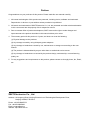
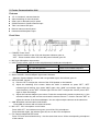
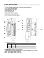
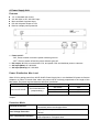
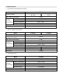
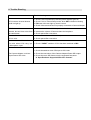
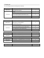
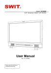
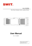
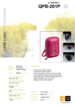
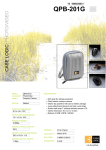
Optical Fiber Camera System
Center Communication Unit
Power Supply Unit
E-1040P
E-2010P
User Manual
Ver: V1.0.0V00
Please read this User Manual
throughout before using.
Camera Adaptor
E-4020A/S
Preface
Congratulations on your purchase of this product. Please read this user manual carefully.
1
. All internal technologies of this product are protected, including device, software and trademark.
Reproduction in whole or in part without written permission is prohibited.
2
. All brands and trademarks of SWIT Electronics Co., Ltd. are protected and other relative trademarks
in this user manual are the property of their respective owners.
3
. Due to constant effort of product development, SWIT reserves the right to make changes and
improvements to the product described in this manual without prior notice.
4
. The warranty period of this product is 2 years, and does not cover the following:
(1) Physical damage to the products.
(2) Any damage caused by using third-party power adaptors.
(3) Any damage or breakdown caused by use, maintenance or storage not according to the user
manual.
(4) The product is disassembled by anyone other than an authorized service center.
(5) Any damage or breakdown not caused by the product design, workmanship, or manufacturing
quality, etc.
5
. For any suggestions and requirements on this product, please contact us through phone, fax, Email,
etc.
SWIT Electronics Co., Ltd.
Address: 10 Hengtong Road, Nanjing Economic and Technological Development Zone,
Nanjing 210038, P.R.China
Phone: +86-25-85805753
Fax: +86-25-85805296
Email: [email protected]
Website: http://www.swit.cc
1. System Connection
Note:
(1) Only CCU, Camera Adapter and Power Supply Unit are included in this user manual.
(2) LEMO (3K.93C) or NEUTRIK (NO2-4FDW-A) cable socket is optional and NEUTRIK cable socket is
compatible with Pure fiber cable connection.
2. Center Communication Unit
Features
◆ 19” 1U includes 4 camera channels
◆ Allow cascading for more channels
◆ Offer Lemo or Neutrik input for option
◆ SONY/Panasonic Camera Remote input
◆ TALLY and return SDI input
◆ Build-in Intercom control panel
◆ Headset and Microphone input
Front View
⑴
⑵ ⑶ ⑷
⑴ POWER: Power on/off
⑵
⑶
⑷
⑸
⑹
⑺
⑻
⑼
⑸
⑹⑺⑻⑼
⑽
⑾
“ON”: Press to switch on the CCU and the power indicator goes on,
“OFF” : Press to switch off the CCU and the power indicator goes off.
MIC:3-pin Microphone input socket
INPUT: Audio switch, used for audio switch between headset and microphone.
Switch to CCU intercom audio input from:
Camera intercom audio output via:
MIC
Only 3-pin Microphone
Speaker and Headset earpiece
HEADSET Only Headset Microphone
Only Headset earpiece
HEADSET: 5-pin headset input socket
Status Indicator: Camera Adaptor signal status indicator.
When the Camera Adaptor connect with recognizable signal, the indicator goes on.
SET/VOLUME: Volume +/a) Revolve “SET” to adjust the volume of the CCU Speaker or the Headset.
b) Adjust the cascading CCU volume: When the “ANN” is switched on, press “SET”, “SET”
indicator light is blinking, then press “ANN” again, then “ANN” red indicator light is blink the
same frequency as the “SET” indicator light. Revolve “SET” to adjust the volume, press “SET”
again to save the settings.
c) Adjust the Camera Adaptor input volume: Press the corresponding camera number key1-4, the
selected number key will turn red to activate the camera volume +/- function. Revolve “SET” to
adjust the volume of the Camera Adaptor. You can adjust multiple cameras at the same time.
ANN: Broadcast communication mode button.
Press ANN to intercom with all camera channels
MIC OFF: CCU microphone mute button
Press “MIC OFF”, the indicator turns green, turn off the CCU microphone.
Press the button again, the indicator goes off, turn on the CCU microphone.
FN: Camera Adaptor MUTE button
Press “FN” and camera Number Key 1-4 at the same time to turn off the corresponding microphone
of the camera.
⑽ Number Key 1-4: Channel select button
⑾
Press the button, the indicator turns yellow, the communication between CCU and Camera Adaptor
is established. Support multiple camera channels simultaneous operation.
Speaker
Rear View
⑴ ⑶⑷
⑵
⑹
⑸
⑺
⑼
⑻
⑽
⑿
⑾
⒀
⒂
⒁
⒃
⑴ VOICE LINK: 4-pin audio cascading socket, connect when cascading another CCU.
⑵ TALLY IN: Switcher TALLY signal input socket (DB9).
⒄ ⒅
Through CCU and fiber cable, TALLY signal transmit to each Camera Adaptor which has build-in
TALLY signal display and output to each monitor’s TALLY display.
RETURN SDI IN: Switcher return SDI input socket. (BNC)
Through CCU and fiber cable, Switcher returned SDI video signal transmits to substation and returns
to camera mounted monitor.
RETURN SDI LOOP: (3) RETURN SDI IN loop output socket, for CCU cascading
OPT FIBER: fiber cable socket, LEMO (3K.93C) or NEUTRIK (NO2-4FDW-A) optional.
NEUTRIK NO2-4FDW-A socket is compatible with Pure fiber socket.
SDI OUT: CH1~CH4 SDI output, every optical channel converts 2 SDI output
The camera video signal will be compiled to the optical signal by Camera Adaptor to CCU through
fiber cable, then CCU will parse the optical signal to SDI signal and output to switcher and monitors.
RCU: 10-pin RCU socket.
Through CCU, fiber cable and Camera Adaptor, RCU output signal will be transmitted to camera to
adjust camera shooting parameters. This socket is compatible with Panasonic 10-pin RCU and
support Sony RCU with the provided 10-pin to 8-pin conversion cable.
DC 12V 4A: Power input socket, only for providing power to CCU.
DC 48V 9A: Power input socket, to connect with power station E-2010 to provide power to CCU, and
through fiber cable to supply power to cameras.
⑶
⑷
⑸⑻⑾⒁
(
⑹⑼⑿⒂
)
⑺⑽⒀⒃
⒄
⒅
Supported SDI video formats:
SMPTE-425M
SMPTE-274M
SDI
1080P (60 / 59.94 / 50)
1080i (60 / 59.94 / 50)
1080p (30 / 29.97 / 25 / 24 / 23.98)
SMPTE-RP211
1080psf (30 / 29.97 / 25 / 24 / 23.98)
SMPTE-296M
720p (60 / 59.94 / 50)
SMPTE-125M
480i (59.94)
ITU-R BT.656
576i (50)
3. Camera Optical Fiber Adaptor
Features
◆ Convert Camera SDI and control signal to Optical and interconnect with CCU
◆ Lemo / Neutrik connection optional
◆ Camera SDI input and loop output
◆ Switcher Return SDI output
◆ Return SDI on/off control
◆ TALLY display and output to monitor
◆ Headset input, Volume +/- adjustment
◆ Sony / Panasonic camera remote input
◆ V-mount or Gold mount camera installation
⑴ STATUS A/B: Status indictor
Status A
on
off
on
Status B
on
on
off
Description
Bi-directional intercom is setup with CCU
CCU has turned off his Microphone
CCU has turned off my channel’s voice
⑵ CHANNEL/VOL: Channel or Volume value display.
The LED displays the volume value when adjust, and other time it displays the channel number.
⑶ VOL+: Camera adaptor headset volume up.
⑷ VOL-: Camera adaptor headset volume down.
⑸ RETURN: When work with SWIT S-1071F(EFP) monitor, press RETURN to switch on/off the return
SDI window on the monitor.
⑹ Headset socket: 5-pin XLR socket, for intercom with the CCU.
⑺ Fiber Cable socket: Transmit power, video, intercom, control signal and Tally. LEMO (3K.93C) or
NEUTRIK (NO2-4FDW-A) is optional, of which NEUTRIK (NO2-4FDW-A) can be directly input with
pure optical fiber cables.
Battery Plate: V-mount or Gold mount battery plate optional.
Fix the camera adaptor on camera battery mount position, and attached with V-mount or Gold mount
battery, so that the battery can power the camera adaptor and camera simultaneously.
TALLY: TALLY light display.
SDI IN: SDI input socket, connected with camera SDI to output signal.
SDI LOOP: SDI loop output socket loop signal output from input
SDI IN, for on-camera monitor.
RETURN OUT: Switcher returned SDI output socket. Output the RETURN IN input signal of CCU.
CAM REMOTE*: 10-pin camera remote input.
Directly connect to Panasonic camera “REMOTE” socket. By the provided 10-pin to 8-pin conversion
cable, you can connect to SONY camera “REMOTE” socket. The camera remote control signal will be
transmit to CCU by Optical Fiber cable.
TALLY: TALLY and DC power output socket. (7-pin)
Work together with SWIT S-1071F(EFP) monitor and provided 7-pin to DB9 cable, the Camera
Adaptor can output TALLY signal and DC power to S-1071F(EFP) monitor.
RETURN BUTTON: External Return SDI on/off button connection (4-pin)
When work with SWIT S-1071F(EFP) monitor, you can switch on/off the return SDI window on the
monitor by pressing the provided external Return SDI on/off button .
⑻⒃
⑼
⑽
⑾
⑿
⒀
⒁
⒂
,
⑽
* Remote Control Protocol Setting:
The Camera Adaptor supports SONY, Panasonic and JVC camera remote protocol.
For the V-mount plate installed Camera adaptor, the default Remote protocol is SONY’s;
For the Gold mount plate installed Camera adaptor, the default Remote protocol is Panasonic’s;
To change the remote Protocol, please press the button by the following sequence:
VOL , VOL , VOL , VOL , VOL , VOL , VOL , VOL
to enter setting, and then press VOL to switch between "P"-Panasonic, "S"-Sony and “J”-JVC,
and press VOL to save and quit.
+
+ -
-
-
+
+
-
+
-
4. Power Supply Unit
Features
◆ 19” 1U standard rack mount
◆ AC 100-240V or DC 120-370V input
◆ Main and Back Up power input
◆ DC 48V 9A power output to CCU
◆ Build-in multiple power protection
⑴
⑴ Power on/off :
⑵
⑶
⑷
⑵
⑶
⑷
;
“ON”, Press to switch on and the power indicator goes on
“OFF”: Press to switch off and the power indicator goes off.
DC output: 48V/9A, to connect with CCU, and power CCU and distribute power to cameras
AC input (Main): AC 100-240V.
AC input (Backup): AC 100-240V.
Power Distribution Max Load
When CCU is getting power from 48V E-2010P Power Supply Unit, it can distribute DC power to Camera
Adaptors via Lemo or Neutrik fiber cable; the power load is inversely proportional to the length of the
fiber cable. The power load and distance reference is as below:
CCU Power Input
Transmission channel
48V from E-2010P
CH1/CH2/CH3/CH4
(Independently)
Transmission Distance
Max Load
100 meters
90W
200 meters
80W
300 meters
55W
If the distance is too far to supply enough power, please take spare battery to power the Camera
Adaptor.
Protection Mode
Overload Protection
Switched to limited current mode, and will recover to normal
automatically when load dropped down.
Over Voltage Protection
Stopped power output, and will recover to normal when restart
E-2010P.
Over Temperature Protection
Stopped power output, and will recover to normal automatically
when temperature is dropped down.
5. Specifications
⑴ The Center Communication Unit (CCU)
Model
Working Voltage
E-1040P
Main power
30
Backup power
~48V
7~17V
Max. Power Consumption
13.0W
~
10%~90%RH
-20°C~+55°C
10%~90%RH
Working Temperature
Working
Environment
0°C +40°C
Working Humidity
Storage Temperature
Storage Humidity
Dimension
483×297×45mm
Net Weight
2.992Kg
⑵ Camera Optical Fiber Adaptor
Model
Working Voltage
Output Voltage / Current
(to power the camera)
Max. Power Consumption
Working Temperature
Working Humidity
Working
Environment Storage Temperature
Storage Humidity
Battery Plate
Dimension
Net Weight
E-4020A
E-4020S
48V DC fiber cable / 11-15V battery
15V / 6A
4.0W
~
10%~90%RH
-20°C~+55°C
10%~90%RH
0°C +40°C
Gold mount
V-mount
157×65×212mm
157×63×212mm
1.068Kg
⑶ Power Supply Unit
Model
Input Voltage
Output Voltage / Current
Working Temperature
Working
Environment
Working Humidity
Storage Temperature
Storage Humidity
E-2010P
AC 85-264V or DC 120-370V
48V / 9A
-40°C +70°C
20 90%RH, non-condensing
~
~
~
-40°C +85°C
10
~90%RH
Dimension
483×292×45mm
Net Weight
2.534Kg
6. Trouble-Shooting
Problems
Trouble shooting
CCU Intercom channel buttons
could not light up
1. Check if CCU is powered up and the power indicator goes on
2. Check if it is in Volume Setup mode, when SET indicator is blinking
3. FN button will never light up, that is normal.
4. Check if the camera channel is properly connected to Camera Adaptor
CCU Selected the camera
channel, but can’t hear voice from
the cameraman.
1. Increase the volume of CCU speaker or headset.
2. Increase the volume of Camera channel microphone.
3. Check optical fiber connection
Camera side can’t hear the
CCU’s voice.
1. Increase the volume of CCU Microphone.
2. Check optical fiber connection
Camera side can’t hear the CC
U’s voice when CCU using 3-pi
n Microphone input.
1. Check if “INPUT” switcher of CCU has been switched to MIC.
The Camera Adaptor could not
output Return SDI video
1. Check the switcher return SDI input at CCU side
2. Check the connection of the Camera Adaptor Return SDI output
3. Check the return SDI format; see the supported formats at
“6. Specifications- Supported SDI video formats”
7. Packing List
The 4-ch Package includes the following items in package:
CCU
Main Device
Accessories
Description
E-1040P 4-channel CCU
(LEMO/NEUTRIK optional)
1
Headset
1
Gooseneck microphone
1
10-pin to 8-pin(SONY) RCU cable (1.5m) or
10-pin to 10-pin (Panasonic) RCU cable (1.5m)
4
Intercom cascading cable
1
AC-DC adaptor + AC cable
1
Camera Adaptor
Main Device
Accessories
Description
Accessories
4
BNC cable (30cm)
12
10-pin to 8-pin(SONY) remote cable (30cm) or
10-pin to 10-pin (Panasonic) remote cable (30cm)
4
7-pin to DB9 power +TALLY cable (60cm)
4
4-pin external return SDI on/off button (1m)
4
Headset
4
Description
Accessories
1
AC cable
1
DC cable (connected to the CCU)
1
Description
Quantity
S-1071F(EFP) 7” Local/Return SDI Pic-in-Pic monitor
4
Sun hood
4
Cold shoe / Screw ball head
4
Carrying Case
Main Device
Quantity
E-2010P Power Supply Unit
Return SDI Monitor
Main Device
Quantity
E-4020 Camera Adaptor
(Gold mount or V-mount optional,
LEMO/NEUTRIK optional)
Power Supply Unit
Main Device
Quantity
Description
19” 6U fiber case
Quantity
1
Product Registration Link