1
Assembly
Twin Disc, Incorporated
4a.
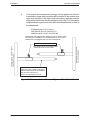
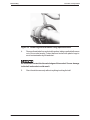
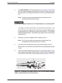
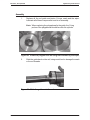
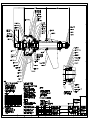
Remove two of the drive unit’s mounting bolts. Bolts to remove will be
directly across from each other (180o apart) at approximately the 3 o’clock
and 9 o’clock positions.
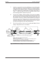
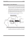
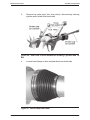
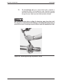
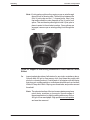
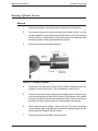
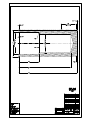
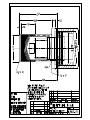
Install the threaded rods of press apparatus, special tool T-21092, into
each hole and attach nuts to the inside of transom to secure rods.
Place the plate of the press apparatus over the propeller shaft to rest
against the aft end of the thrust tube. The threaded rods should pass
through the 1 inch holes on either side of the center hole of the plate.
Secure the plate with nuts. Go to Step 5.
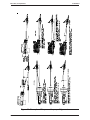
If the socket has been removed from the transom:
2b.
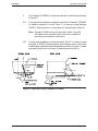
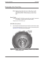
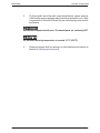
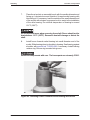
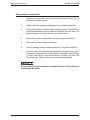
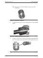
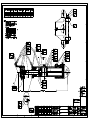
Position the socket in socket bench with larger diameter end facing up.
Coat U-joint yoke splines with lubricating oil to assist in installation of
yoke onto propeller shaft. Place approximately 4mm (0.15 in.) shims in
socket on top of packing.
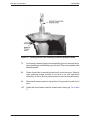
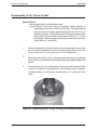
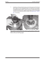
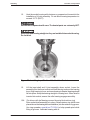
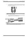
Lift thrust tube and position above thrust socket. Slowly lower thrust tube
into socket.
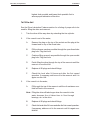
3b.
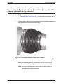
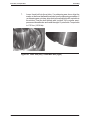
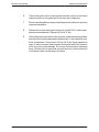
Inspect spherical surface of aft retainer for any nicks, scratches or burrs.
Smooth with 400 grit or finer emery cloth, and clean thoroughly with
alcohol or cleaning solvent. Coat threads of aft retainer with anti-seize
that does not contain graphite or molbdenum disulfide such as Loctite®
White HI-Temp Anti-Seize. Slip ring over thrust tube, and position around
thrust ball.
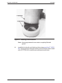
Note: The spherical surface of the two bronze retainers may have
minor dents, scratches or low spots. Smooth edges of
these imperfections by lightly sanding with emery cloth or
400 grit or finer sand paper. High spots are not acceptable
and must be removed.
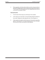
4b.
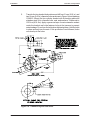
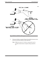
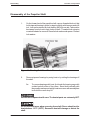
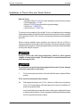
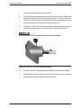
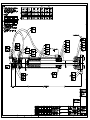
Place the unit horizontally in the assembly stand. Position the socket so
the flat end of its mounting flange is facing the same direction as the fin
mount on the thrust tube.
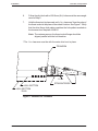
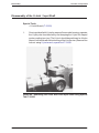
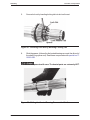
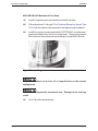
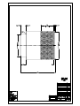
Install the threaded rods of press apparatus, special tool T-21092,
through the mounting plate bolt holes in the 3 o’clock and 9 o’clock
positions. Attach nuts on the forward end of the threaded rods.
Pass the threaded rods through the 1-inch bolt holes in the press
apparatus plate. Attach nuts to the aft end of the threaded rod. Go to
Step 5.
Arneson Surface Drive Service Manual #1015710
131