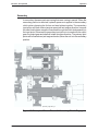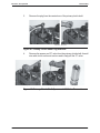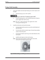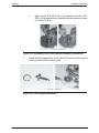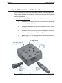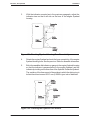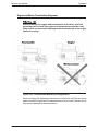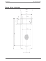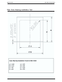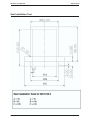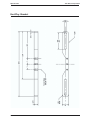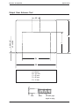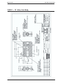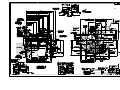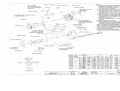
1
TWIN DISC
INCORPORA
TED
INCORPORATED
Ser vice
Manual
Marine
Transmission
Components:
MGX-5135SC
Document Number: 1022127
NOTICE
Twin Disc, Incorporated makes no warranty or guaranty of any
kind, expressed, implied or otherwise, with regard to the
information contained within this manual. Twin Disc, Incorporated
has developed this manual through research and testing of the
information contained therein. Twin Disc, Incorporated assumes
no responsibility for any errors that may appear in this manual
and shall not be liable under any circumstances for incidental,
consequential or punitive damages in connection with, or arising
out of, the use of this manual. The information contained within
this manual is subject to change without notice.
Document Number
1022127
July, 2005
Marine Transmission
Service Manual
TWIN DISC, INCORPORATED
EXCLUSIVE LIMITED WARRANTY
MARINE PLEASURE CRAFT TRANSMISSION
A. Twin Disc, Incorporated warrants all assembled products and parts, (except component products or parts on which written warranties
issued by the respective manufacturers thereof are furnished to the original customer, as to which Twin Disc, Incorporated makes no
warranty and assumes no liability) against defective materials or workmanship for a period of thirty six (36) months from the date of
original shipment by Twin Disc, Incorporated to the original customer, but not to exceed twenty four (24) months of service, whichever
occurs first. This is the only warranty made by Twin Disc, Incorporated and is in lieu of any and all other warranties, express
or implied, including the warranties of merchantability or fitness for a particular purpose and no other warranties are implied
or intended to be given by Twin Disc, Incorporated. This warranty applies only to private, non commercial (non revenue
earning) marine pleasure craft applications delivered by Twin Disc, Incorporated to the original customer on or after May 1,
1995.
The original customer does not rely upon any tests or inspections by Twin Disc, Incorporated or on Twin Disc,
Incorporated's application engineering. Twin Disc, Incorporated is not responsible for any specific application, installation of
performance standard. Any analysis program by Twin Disc, Incorporated based upon customer supplied information is done solely as
an accommodation to the customer and is not to be interpreted or construed as an approval for specific application or a guarantee of
performance. Twin Disc, Incorporated cannot be held liable or responsible for incorrect information supplied or deviations from
specifications provided by customer..
B. The exclusive remedy provided by Twin Disc, Incorporated whether arising out of warranty within the applicable warranty
period as specified, or otherwise (including tort liability), shall at the sole option of Twin Disc, Incorporated be either the
repair or replacement of any Twin Disc, Incorporated part or product found by Twin Disc, Incorporated to be defective. For
all models except MG340 and MG360 this include the labor to perform that work and to remove and reinstall (or equivalent
credit). In this context, labor is defined as the flat rate labor hours established by Twin Disc, Incorporated in the published
Twin Disc Flat Rate Schedule, required to remove, disassemble, inspect, repair, reassemble, reinstall and test the Twin Disc,
Incorporated product only. Authorized reasonable travel and living expenses will be considered for payment in all model
except MG340 and MG360. Under no circumstances, including a failure of the exclusive remedy, shall Twin Disc,
Incorporated be liable for economic loss, consequential, incidental or punitive damages..
The above warranty and remedy are subject to the following terms and conditions:
1. Complete parts or products upon request must be returned transportation prepaid and also the claims submitted to Twin Disc,
Incorporated within sixty (60) days after completion of the in warranty repair.
2. The warranty is void if, in the opinion of Twin Disc, Incorporated, the failure of the part or product resulted from abuse, neglect,
improper maintenance or accident.
3. The warranty is void if any modifications are made to any product or part without the prior written consent of Twin Disc,
Incorporated.
4. The warranty is void unless the product or part is properly transported, stored and cared for from the date of shipment to the date
placed in service.
5. The warranty is void unless the product or part is properly installed and maintained within the rated capacity of the product or part
with installations properly engineered and in accordance with the practices, methods and instructions approved or provided by Twin
Disc, Incorporated.
6. The warranty is void unless all required replacement parts or products are of Twin Disc origin or equal, and otherwise identical with
components of the original equipment. Replacement parts or products not of Twin Disc origin are not warranted by Twin Disc,
Incorporated.
C. As consideration for this warranty, the original customer and subsequent purchaser agree to indemnify and hold Twin Disc,
Incorporated harmless from and against all and any loss, liability, damages or expenses for injury to persons or property, including
without limitation, the original customer's and subsequent purchaser's employees and property, due to their acts or omissions or the
acts or omissions of their agents, and employees in the installation, transportation, maintenance, use and operation of said equipment.
D. Only a Twin Disc, Incorporated authorized factory representative shall have authority to assume any cost or expense in the service,
repair or replacement of any part or product within the warranty period, except when such cost or expense is authorized in advance in
writing by Twin Disc, Incorporated.
E. Twin Disc, Incorporated reserves the right to improve the product through changes in design or materials without being obligated to
incorporate such changes in products of prior manufacture. The original customer and subsequent purchasers will not use any such
changes as evidence of insufficiency or inadequacy of prior designs or materials.
F. If failure occurs within the warranty period, and constitutes a breach of warranty, repair or replacement parts will be furnished on a no
charge basis and these parts will be covered by the remainder of the unexpired warranty which remains in effect on the complete unit.
July 1, 2004
TDWP2004 rev 2004
TWIN DISC, INCORPORATED
FLAT RATE HOUR ALLOWANCE
MARINE PLEASURE CRAFT TRANSMISSION
(Hourly Labor Rates Must Be Acceptable to Twin Disc, Incorporated)
MODEL SERIES
R&R
UNIT REBUILD
•
•
MG340, MG360…………………………………………….0.0
MG502, MG5005, MG5010, MG5011,
MG5012, MG5015, MG5020…………………………… 10.0
•
MG506, MG5061, MG5061, MG5061, MG5062,
MG5065, MG5050, MG5055…………………………… 10.0
11.0
•
MG507, MG5081, MG5085, MG5090
MG5075, MG5091……………………………………… 10.0
12.0
MG5112, MG5113, MG5085, MG5091, MG5090,
MG509, MG 5111, MG5114, MGX5114………………. 10.0
17.0
MG514C, MG514M, MG5141, MG514CHP
MGX5135, MGX5145, MGX5147………………………. 10.0
25.0
•
•
•
MG516, MG5161, MG5170…………………………….. 10.0
28.0
MG518-1………………………………………………….. 10.0
32.0
MG520-1, MG 5202, MG5203, MG5204,
MG5205, MG6449, MG6557…………………………… 10.0
32.0
•
MG530, MG530M, MG5301,MG6650, MG6690,
MG6848, MG6598, MG6600, MG6619, MG6620,
MG6984, MG61242, MGX6650, MGX6690,
MGX6848…………………………………………………. 12.0
32.0
•
MGN80, MGN232, MGN233, MGN272, MGN273,
MGN332, MGN334, MGN335, MGN432, MGN433,
MGN472, MGN493………………………………………. 10.0
32.0
•
MGN650, MGN800, MGN1000, MGN1400,
MGN1600………………………………………………… 20.0
62.0
•
•
PUMP (ALL MODELS EXCEPT MG340 & MG360) .… 1.0
-
•
•
VALVE (ALL MODELS EXCEPT MG340 & MG360)… 1.0
July 1, 2004
0.0
8.0
.5
TDWP2004A rev 2004
Twin Disc, Incorporated
Table of Contents
Table of Contents
Introduction ......................................................... 11
General Information .......................................................................... 11
Safety and General Precautions ..................................................... 11
Preventative Maintenance ................................................................ 13
Towing................................................................................................. 13
Ordering Parts and Obtaining Services ......................................... 14
Source of Service Information......................................................... 15
Warranty .............................................................................................. 15
Description and Specifications .........................17
General................................................................................................ 17
Power Ratings .................................................................................... 19
Changing Rotation ............................................................................. 19
Direction of Drive ............................................................................... 19
Construction Features ...................................................................... 20
Lubrication Features......................................................................... 21
Heat Exchanger ................................................................................. 23
Specifications and Maintenance ..................................................... 25
Oil Pressures ..................................................................................... 27
Optional Equipment .......................................................................... 28
Torque Values for Fasteners ........................................................... 31
Clutch Plate Wear Limits ................................................................... 34
Operation ..............................................................35
General................................................................................................ 35
General Overview of GP Control Valve with Electronic Interface36
Hydraulic System with GP Control Valve ....................................... 43
Power Take-off (Optional) ................................................................. 47
Power Flow ......................................................................................... 48
Preventative Maintenance ..................................53
In-boat Maintenance and Repair ..................................................... 53
General Maintenance ........................................................................ 54
Periodic Visual Inspection ............................................................... 56
Marine Transmission Service Manual 1022127
7
Table of Contents
Twin Disc, Incorporated
Troubleshooting ..................................................59
Troubleshooting of Electric Control Valve .................................... 59
Pressure Test Kit ............................................................................... 60
Troubleshooting of GP Control Valve with Electronic Interface. 61
Disassembly ........................................................65
Prepare Transmission for Disassembly ........................................ 65
Prior to Removal ................................................................................ 67
Remove External Parts ..................................................................... 68
Remove Internal Parts....................................................................... 77
Remove Output Gear and Shaft ....................................................... 88
Primary Clutch Shaft Disassembly ................................................. 95
Secondary Clutch Shaft Disassembly .......................................... 100
Disassembly of GP Control Valve with Electronic Interface ..... 105
Disassembly ..................................................................................... 106
Cleaning and Inspection .................................. 113
Cleaning ............................................................................................ 113
Inspection ......................................................................................... 115
Assembly ............................................................ 119
General .............................................................................................. 119
Prior to Assembly - Output End Bearings .................................... 121
Primary Shaft Assembly ................................................................. 122
Secondary Shaft Assembly ............................................................ 127
Main Housing Assembly ................................................................. 132
Output Gear and Output Shaft Assembly ..................................... 133
Bearing Preload Measurement and Shimming ........................... 141
Rear Bearing Cups .......................................................................... 144
Install External Components .......................................................... 154
Assembly of GP Control Valve with Electronic Interface ........... 162
Adjustment of Main Pressure ........................................................ 166
Installation ..........................................................169
Prior to Installation .......................................................................... 169
Alignment (also reference SAE J-1033 and J-617) ..................... 170
Alignment .......................................................................................... 173
Electrical Controls Installation....................................................... 179
Wiring Connections ......................................................................... 181
8
Marine Transmission Service Manual 1022127
Twin Disc, Incorporated
Table of Contents
Special Tools .....................................................185
List of Special Tools ........................................................................ 185
Recommended Pump Set and Fluids ........................................... 186
Release Spring Compressor ......................................................... 188
Special Bearing Races .................................................................... 189
Front Outer Bearing Race Installation Tool ................................. 190
Inner Bearing Race Installation Tool............................................. 191
Rear Outer Bearing Installation Tool ............................................ 192
Seal Installation Tool ....................................................................... 193
End-Play Bracket ............................................................................. 194
Output Gear Advance Tool ............................................................. 195
1020117 - “S” Valve Test Body ...................................................... 196
B2408AL “S” Valve Test Procedure ............................................. 197
Engineering Drawings ......................................199
List of Engineering Drawings ........................................................ 199
Marine Transmission Service Manual 1022127
9
Table of Contents
Twin Disc, Incorporated
NOTES
10
Marine Transmission Service Manual 1022127
Twin Disc, Incorporated
Introduction
Introduction
General Information
This publication provides service information for the Twin Disc MGX-5135SC
marine transmission. Specific engineering details and performance
characteristics can be obtained from the Product Service Department of Twin
Disc, Incorporated, Racine, Wisconsin, USA.
Operation and maintenance personnel responsible for this equipment should
be familiar with this publication and have it at their disposal. A thorough
understanding and application of the material in this manual will result in
consistent performance from the unit and help reduce downtime.
Safety and General Precautions
General
All personnel servicing this equipment should employ safe operating practices.
Twin Disc, Inc. will not be responsible for personal injury resulting from careless
use of hand tools, lifting equipment, power tools, or unacceptable maintenance/
working practices.
Marine Transmission Service Manual 1022127
11
Introduction
Twin Disc, Incorporated
Important Safety Notice
Proper installation, maintenance, and operation procedures must be followed
due to the possible danger to person(s) or property from accidents that may
result from the use of machinery. Twin Disc, Inc. will not be responsible for
personal injury resulting from careless maintenance/working practices.
Inspect as necessary to assure safe operations under prevailing conditions.
Proper guards and other safety devices that may be specified in safety codes
should be provided. These devices are neither provided by, nor are they the
responsibility of Twin Disc, Inc.
Selecting NEUTRAL disengages transmission clutches but does not
prevent propeller shaft rotation. If you require positive neutral (propeller
shaft locked), a shaft brake or other shaft-locking device must be used.
To prevent accidental starting of the engine when performing routine
transmission maintenance, disconnect the battery cables from the
battery and remove ignition key from the switch.
Most Twin Disc products have provisions for attaching lifting bolts. The
holes provided are always of adequate size and number to safely lift
the Twin Disc product. These lifting points must not be used to lift the
complete power unit. Lifting excessive loads at these points could cause
failure at the lift point (or points) and result in damage or personal injury.
Select lifting eyebolts to obtain maximum thread engagement with bolt
shoulder tight against housing. Bolts should be near but should not
contact bottom of bolt hole.
12
Marine Transmission Service Manual 1022127
Introduction
Twin Disc, Incorporated
Preventative Maintenance
Frequent reference to the information provided in the Marine Transmission
Owner’s Manual, 1016313, regarding daily operation and limitations of this
equipment will assist in obtaining trouble-free operation. Schedules are provided
for recommended maintenance of the equipment.
Towing
Under the conditiions described below, the prop shaft must be locked
in place to prevent backdriving. Failure to do this can damage the marine
transmission due to lack of component lubrication
Backdriving (also called windmilling) occurs when an engine is shut down and
the propeller shaft is being driven by the flow of water across the propeller,
which, in turn, rotates the components in the marine transmission. During
backdriving conditions, the transmission does not receive proper lubrication.
Conditions where backdriving may occur:
!
Vessel is being towed.
!
One or more engines on a multiple-transmission vessel are shut down
while under way.
!
Sailboat under sail with auxiliary engine shut down.
!
Vessel tied up or docked in a heavy current.
Any of the following solutions are applicable if any of the above
conditions are present:
!
Lock the propeller shaft to prevent rotation.
!
Add an optional trailing oil pump into the lubrication circuit.
Refer to the hydraulic system schematics for more details on the optional trailing
pump specifications for the applicable transmission, or contact your Twin Disc
Authorized Distributor.
Marine Transmission Service Manual 1022127
13
Introduction
Twin Disc, Incorporated
Ordering Parts and Obtaining Services
All replacement parts or products (including hoses and fittings) must
be of Twin Disc origin or equal, and otherwise identical with components
of the original equipment. Use of any other parts or products will void
the warranty and may result in malfunction or accident, causing injury
to personnel and/or serious damage to the equipment.
Ordering Service Parts
Renewal parts, service parts kits, optional equipment and product service
assistance may be obtained from any authorized Twin Disc distributor or service
dealer. Contact Twin Disc for the distributor or service dealer near you.
Note: Do not order parts using the part numbers on the crosssectional drawings. These numbers may be referenced
for part identification; however, they should be verified on
the bill of material (BOM) before an order is placed. BOM
numbers are stamped on the unit nameplate.
Twin Disc, having stipulated the bill of material number on the unit’s nameplate,
absolves itself of any responsibility resulting from any external, internal, or
installation changes made in the field without the express written approval of
Twin Disc. All returned parts, new or old, resulting from any of the above stated
changes will not be accepted for credit. Furthermore, any equipment that has
been subjected to such changes will not be covered by a Twin Disc warranty.
14
Marine Transmission Service Manual 1022127
Twin Disc, Incorporated
Introduction
Source of Service Information
For the latest service information on Twin Disc products, contact any Twin Disc
distributor or service dealer. This can be done on the Twin Disc corporate web
site found at [http://www.twindisc.com]. Provide your model number, serial
number and bill of material number to obtain information on your unit. If
necessary, contact the Product Service Department, Twin Disc, Incorporated,
Racine, Wisconsin 53405-3698, USA by e-mail at [email protected].
Warranty
Equipment for which this manual was written has a limited warranty. For details
of the warranty, refer to the warranty statement at the front of this manual. For
details of the warranty, contact any Twin Disc Authorized Distributor, service
dealer, or the Warranty Administration Department, Twin Disc, Inc., Racine,
Wisconsin, U.S.A.
Marine Transmission Service Manual 1022127
15
Introduction
Twin Disc, Incorporated
NOTES
16
Marine Transmission Service Manual 1022127
Description and Specifications
Twin Disc, Incorporated
Description and Specifications
General
The MGX-5135SC is a reverse and reduction transmission with the additional
Quickshift™ feature. The output shaft is parallel ot the input shaft. The MGX5135SC offers conical gearing for quieter operation and is available in the
rollowing ratios: 1.00:1, 1:10:1, 1.28:1, 1.48:1, 1.73:1, 2.04:1, 2.57:1, and 2.90:1.
The MGX-5135SC transmission is controlled by hydraulics. Both the primary
and secondary clutches are operated by main pressure oil supply. The bearings,
clutches and gears are lubricated and cooled with low pressure oil.
Drawing PX-11840 identifies the installation information for the MXG-5135SC
marine transmission.
Marine Transmission Service Manual 1022127
17
Description and Specifications
Twin Disc, Incorporated
Nameplate
The nameplate identifies the model, bill of material (BOM) and the serial number
of the unit. These numbers are necessary to identify the correct parts for your
transmission.
TM
BOM
NO.
MARINE TRANSMISSION
SERIAL
NO.
LUBRICATION:
EVERY 10 SERVICE HOURS OR DAILY:
CHECK OIL LEVEL
WITH ENGINE RUNNING AND MARINE TRANSMISSION IN NEUTRAL.
RATIO
CUSTOMER
NO.
DRAIN AND REFILL HOUSING WITH CLEAN OIL. REMOVE AND REPLACE
FILTER ELEMENT.REMOVE, CLEAN AND REPLACE SUCTION SCREEN
IN REAR COVER.
IMPORTANT:
WARRANTY IS VOID UNLESS TRANSMISSION IS
LUBRICATED AND MAINTAINED AS SPECIFIED IN THE SERVICE MANUAL
AVAILABLE ON REQUEST. REFER TO "MARINE TRANSMISSION LUBRICANT"
PLATE SHIPPED WITH UNIT. BILL OF MATERIAL NO. MUST BE GIVEN
WHEN ORDERING PARTS.
MADE IN BELGIUM.
MIN. OIL PRESSURE
AT RATED RPM
psi
BAR
OIL CAPACITY
gal
L
P11954
EVERY 1000 SERVICE HOURS OR 6 MONTHS,
WHICHEVER COMES FIRST:
TWIN DISC INCORPORATED RACINE, WI 53403
MODEL
NO.
U.S. PATENT NO. 6,443,286
EUR. PATENT NO.
P11954
Figure 1. Example of MGX-5135SC Nameplate
18
Marine Transmission Service Manual 1022127
Twin Disc, Incorporated
Description and Specifications
Power Ratings
The MGX-5135SC transmission can be operated through either the primary
shaft or secondary shaft at its full rated horsepower when driven by a standard
right hand rotation engine (counterclockwise flywheel rotation direction when
viewing rear of engine).
Always reference the Bill of Materials (BOM) or Specification number when
ordering service parts.
Changing Rotation
When shipped form the factory, each unit is designated for use with a particular
engine rotation. Within their rated capacities, these units may be operated
continuously in either forward or reverse.
The unit can be adapted to either left or right-hand engine rotation. To adapt to
opposite engine rotation, remove the heat exchanger hose from the rear end of
the pump. Remove the pump, turn it 180° and reinstall it. Remove the plug from
the rear of the pump and install where the heat exchanger hose was. Install the
heat exchanger hose where the plug was. When changing from RH rotation to
LH rotation install an engine rotation plate (Arrow) to indicate the new direction
of rotation.
Direction of Drive
The primary (input) clutch shaft and driving transfer gear always rotates in engine
direction. The secondary clutch shaft and driven transfer gear always rotate in
anti-engine direction because the driven transfer gear is meshed with the driving
transfer gear on the primary clutch shaft. When the primary clutch is engaged,
the primary input pinion rotates in engine direction. The output gear, which is
secured to the output shaft, is meshed with the primary input pinion and so the
output gear and shaft are driven in anti-engine direction. When the secondary
clutch is engaged, the secondary input pinion rotates in anti-engine direction.
The output gear is meshed with the secondary input pinion and, therefore, the
output gear and shaft are driven in engine direction.
Marine Transmission Service Manual 1022127
19
Description and Specifications
Twin Disc, Incorporated
Construction Features
Housings
The MGX-5135SC transmission has a one piece main housing with a bolt on
SAE #1 or SAE #0 engine housing adapter. A manifold and a top cover, sealed
with gaskets, bolts onto the housing. An end cover is located on the primary
shaft and a pump located on the secondary shaft completes the housing
enclosure.
Taper Roller Bearings
The primary and secondary clutch shafts are supported and located by tapered
roller bearings. The pinions are supported on bushings and the end movement
limited by thrust washers. Bearing clearances for each clutch shaft are set by
use of a single shim pack at the rear-tapered roller bearing on each shaft.
Tapered roller bearings support the output shaft and have bearing clearance
adjusted by use of shims.
Oil Pump Drive
The oil pump is tang-connected and driven by the secondary clutch shaft.
20
Marine Transmission Service Manual 1022127
Twin Disc, Incorporated
Description and Specifications
Lubrication Features
The MGX-5135SC transmission bearings and clutches on the primary and
secondary shafts are lubricated through oil passages drilled in the shafts. The
output shaft bearing, transfer gears, primary and secondary pinions and their
bearings are gravity and splash lubricated.
Suction Strainer
The marine transmission has a serviceable suction strainer located below the
oil pump. The strainer is between the sump and the oil pump in the hydraulic
circuit. The strainer can be replaced if necessary.
Oil Filter Assembly
A spin-on oil filter is a standard feature on MGX-5135SC transmissions. The
filter is located between the heat exchanger outlet and the selector valve in the
hydraulic circuit. The replacement element should be replaced at 1000 hours
or six-month intervals, whichever comes first. The replacement filter part number
is PM11652.
Gears
All gears are helical, carburized, hardened and ground for smooth quiet
operation. All gears are in constant mesh. The primary and secondary transfer
gears and the output gear are mounted on keyless tapers.
Marine Transmission Service Manual 1022127
21
Description and Specifications
Twin Disc, Incorporated
Flexible Torsional Input Coupling
The purpose of the torsional coupling is to transmit power from the engine to
the marine transmission through a rubber or silicone element that will:
!
Dampen torsional vibrations
!
Change the natural frequencies of a system to move critical frequencies
out of the operating speed range
!
Accommodate a certain amount of misalignment
!
Absorb shock and reduce noise
!
Minimize gear “rattle”
Several couplings are available from Twin Disc, and are selected based on the
customer supplied engine information. Final coupling selection must be
confirmed by the packager based on the torque/rpm ratings and the results of
the system torsional vibration analysis (TVA), and on engine rotation. Care
must be taken when servicing that replacement couplings are matched to this
criteria.
22
Marine Transmission Service Manual 1022127
Twin Disc, Incorporated
Description and Specifications
Heat Exchanger
The heat exchanger is designed to maintain the oil in the hydraulic system of
the marine transmission at the proper temperature by passing coolant from the
engine through the heat exchanger. The heat exchanger is mounted on a special
bracket bolted on the live PTO face. The special brackets allow either live PTO
connection or clutchable PTO and no PTO as well. In case of remote mounting,
the heat exchanger should be installed in a location convenient to both engine
coolant and marine transmission oil.
Figure 2. Heat Exchanger
Marine Transmission Service Manual 1022127
23
Description and Specifications
Twin Disc, Incorporated
Table 1. Heat Exchanger Requirements
HEAT EXCHANGER (H.E.) REQUIREMENTS
PERMISSIBLE OIL TEMPERATURE INTO HEAT EXCHANGER
RATIO
MAX.
OIL VISCOSITY
MIN.
ALL RATIOS
SAE 30
85˚C(185˚F)
65˚C(150˚F)
ALL RATIOS
SAE 40
99˚C(210˚F)
80˚C(175˚F)
MIN. HEAT TRANSFER CAPACITY
APPLY APPROPRIATE SERVICE FACTOR
FOR FRESH AND RAW WATER
APPROX. OIL FLOW TO H.E.
KW(BTU/MIN) PER ENGINE RTD. H.P.
CONTINUOUS DUTY
.026(1.484)
P.C. & INT. DUTY
.022(1.272)
2.3 L/MIN(.61 GPM) PER 100 ENGINE R.P.M.
PEAK OIL PRESSURE AT H.E. (PROOF TEST H.E. AT 1,5 X KPa(PSI)
1965 KPa(285 PSI)
MAX. ALLOWABLE OIL PRESSURE DROP ACROSS H.E. WITH
6 6 m m 2/ s e c ( 3 0 0 S U S ) O I L A T R A T E D E N G I N E R . P . M
207 KPa
(30 PSI)
WATER FLOW TO H.E. - USE 1.5 TO 3.0 TIMES OIL - L/MIN.(GPM)
H.E. WATER PRESSURE RATING, MIN., = 1.5 X H.E. INLET WATER KPa(PSI)
DATA H.E. PURCHASER MUST ALSO TELL VENDOR
STATE IF RAW (OPEN CHANNEL & SEA) OR FRESH (CLOSED
ENGINE JACKET * AND/OR KEEL COOLER) WATER WILL COOL H.E.
STATE MAX. WATER TEMP. INTO H.E. -- TYPICAL: RAW WATER - 29˚C-32˚C (85˚F-90˚F), KEEL
C O O L E R W A T E R 4 6 ˚ C - 6 0 ˚ C ( 1 1 5 ˚ F - 1 4 0 ˚ F ) , E N G I N E J A C K E T W A T E R* 7 4 ˚ C - 8 5 ˚ C ( 1 6 5 ˚ F - 1 8 5 ˚ F ) .
STATE MIN., ALSO MAX. L/MIN. (GPM) OF WATER FLOW TO H.E.
H.E. INSTALLATION & SERVICE REQUIREMENTS
OIL LINES, TRANSMISSION TO H.E. AND RETURN ---(1) MAX. VELOCITY IN FITTINGS,PIPE,HOSE AND TUBES-7,6m/sec (25FT./SEC.)
(2) BURST PRESSURE, MIN., = 10 x PEAK OIL PRESSURE AT H.E.
(3) HOSE - SAE J517 100R1 MEETING USCG 46CFR 56.60-25(C),135˚C
(275˚F) TEMP. RATING
(4) PROTECT LINES FROM MECHANICAL DAMAGE. ZINC ANODES PROTECT
H.E. RAW WATER PASSAGES FROM CORROSION. CHECK & REPLACE
T H E M F R E Q. U E N T L Y .
B3649H
24
Marine Transmission Service Manual 1022127
Description and Specifications
Twin Disc, Incorporated
Specifications and Maintenance
Frequent reference to this data and application of the information will result in
better service from the transmission.
Oil Capacity
15.1 Liters (4.0 US Gal.) less hoses and heat exchanger.
The transmission should be warmed to operating temperature when oil is
checked.
Oil Pump Capacity
14.1 GPM @ 1800 RPM.
Minimum Oil Pressure When Cruising
Check your unit’s identification plate. MGX-5135SC has a minimum oil pressure
at rated engine RPM, located on the name plate, of 1860 kPa (270 psi) non
trolling mode.
Maximum Input Speed
2500 RPM.
Dry Weight
Approximately 300 Kg (661 lbs).
Type of Oil and Oil Viscosity
Note: Multi-viscosity oils (i.e. 10W-20 etc.) should not be used
in Twin Disc MarineTransmissions.
The recommended oil is mentioned on the lubricant nameplate located on the
housing of your Marine Gear.
Marine Transmission Service Manual 1022127
25
Description and Specifications
Twin Disc, Incorporated
Table 2. Marine Transmission Lubricant
MARINE TRANSMISSION LUBRICANT
OIL SERVICE CLASS- USE S.A.E. -API SERVICE CLASS
CD ENGINE OIL CERTIFIED BY VENDOR TO PASS TO-2
OIL TEST. ALSO APPROVED ARE S.A.E.-API SERVICE
CLASS CC ENGINE OIL, MIL-L-2104B, AND
TRANSMISSION FLUID TYPE C-3.
VISCOSITY- BASE SELECTION ON SUMP OIL TEMP.
CONDITIONS TABULATED BELOW.
START-UP
32 F MIN.
(0 C MIN.)
32 F MIN.
(0 C MIN.)
STEADY OPERATION
150 -150 F
(65 -85 C)
175 -210 F
(80 -99 C)
VISCOSITY
S.A.E. NO. 30
S.A.E. NO. 40
STEADY OPERATION BELOW 150 F (65 C) OR ABOVE
210 F (99 C) IS NOT RECOMMENDED.
INCORPORATED
RACINE, WI. 65403 U.S.A.
B2411D
B2411D
26
Marine Transmission Service Manual 1022127
Description and Specifications
Twin Disc, Incorporated
Oil Pressures
The following tables give oil pressures at different speeds and ranges. Check
your unit’s identification plate for the “Minimum Oil Pressure When Cruising”.
Use this value to determine which table applies to your unit. See MGX-5135SC
rear view for location of oil pressure checkpoints.
Table 3. 2414 kPa (350 psi) Transmission Oil Pressure Specifications
Lim its for Ma rine Tra nsm ission Equippe d w ith 2414 kPa (350 psi) Proportiona l Va lve s
Input
Speed
Shift
Position
Main Pressure at
Valve Inlet
Prim ary
Clutch Min.
Secondary
Clutch Min.
kPa
psi
kPa
psi
kPa
psi
kPa
psi
600
Neutral
1759-1897
255-275
0
0
0
0
21-69
3-10
600
Prim ary
1759-1897
255-275
1724
250
0
0
14-55
2-8
600
Secondary
1759-1897
255-275
0
0
1724
250
14-55
2-8
1800
Neutral
1862-2000
270-290
0
0
0
0
124-276
18-40
1800
Prim ary
1862-2000
270-290
1828
265
0
0
124-241
18-35
1800
Secondary
1862-2000
270-290
0
0
1828
265
124-241
18-35
Lube
Note: Cooling temperature range: Delvac 1110 oil at 29-35°C
(85-95°F) or Mobilkote 501 at 32-38°C (90-100°F).
Required: Primary lube pressure = secondary lube
pressure within 21 kPa (3 psi).
Primary and secondary clutches must be within 21 kPa (3
psi) of each other.
ALL SHIFTS MUST BE DONE AT OR BELOW 1800 RPM.
Table 4. Limits for Marine Transmission Equipped with Hydraulic Clutched PTO
Limits for Marine Transmission Equipped with Hydraulic Clutched PTO
Input
rpm
PTO Control Valve
Disengaged
Actual
kPa
psi
PTO Control Valve
Engaged
kPa
psi
kPa
psi
600
0
0
1793-1931
260-280
1800
0
0
1896-2000
275-290
600
0
0
1759-1862
255-270
1800
0
0
1827-1966
265-285
Actual
kPa
psi
Transmission
Control Valve
Engaged
Transmission
Control Valve
Disengaged
Note: Transmission control valve is the right valve and the PTO
valve is the left valve, when viewed the rear of the
transmission.
Marine Transmission Service Manual 1022127
27
Description and Specifications
Twin Disc, Incorporated
Optional Equipment
The following optional equipment is available for the MGX-5135SC marine
transmission (except where noted) through the nearest authorized Twin Disc
distributor.
Power Take-off
A live pump-mount power take-off is available in sizes SAE J-744 No. 127-4
and SAE J-744 No. 32-4 (SAE “C”, 4-bolt).
A clutchable pump mount power take-off is available in sizes SAE J-744
No. 127-4 and SAE J744 No. 32-4.
A clutchable shaft drive power take-off is available.
PTO adapter from SAE J-744 size 127-4 to 101-4 (SAE “C” to SAE “B”).
Mounting Brackets
Steel fabricated mounting brackets for rigid mounting are available.
Torsional Input Coupling
Several models of torsional input couplings are available, including Silicon
Vulkan (VKE) and Centa (CF-R).
Heat Exchanger
A heat exchanger is available, shipped loose or mounted.
Companion Flange Assembly
The companion flange assembly consists of the companion flange
and mounting hardware.
Trolling Valve
An electronic E-troll module is available.
28
Marine Transmission Service Manual 1022127
Description and Specifications
Twin Disc, Incorporated
Table 5. Bearing Preload Specifications
Transmission Primary and Secondary Shaft Tapered Roller Bearing Preload
Assembly No.
Minimum
Ma ximum
All
0.00 mm (0.000 in.)
+0.05 mm (+0.002 in.)
Transmission Ouptut Shaft Bearing Preload
Assembly No.
Minimum
Maximum
All
+0.13 mm (+0.005 in.)
+0.18 mm (+0.007 in.)
Note: A negative endplay indicates a pre-load condition.
Table 6. Maximum Allowable Total Indicator Runout
Maximum Allowable Total
Indicator Reading
Feature
Face of SAE #0 cover adapter from input spline
0.30 mm (0.012 in.)
Face of SAE #1 cover adapter from input spline
0.25 mm (0.010 in.)
Pilot of SAE #0, SAE #1 cover adapter from input spline
0.20 mm (0.008 in.)
Face of output flange near OD from housing
0.10 mm (0.004 in.)
Pilot of output flange from housing
0.10 mm (0.004 in.)
Table 7. Ouput Gear Advance
Minimum
Actual
Maximum
3.81 mm (0.150 in.)
5.33 mm (0.210 in.)
Table 8. Transfer Gear Advance
Shaft
Minimum
Prim ary
5.33 m m (0.210 in.)
6.86 m m (0.270 in.)
Secondary
5.33 m m (0.210 in.)
6.86 m m (0.270 in.)
Marine Transmission Service Manual 1022127
Actual
Maximum
29
Description and Specifications
Twin Disc, Incorporated
Table 9. Clutch Pack Clearance
Clutch Pa ck Endpla y
Sha ft
Minim um
Actua l
Ma x im um
P rim ary
2.30 mm (0.019 in.)
3.20 m m (0.126 in.)
Secondary
2.30 mm (0.019 in.)
3.20 m m (0.126 in.)
Table 10. Sequence Valve Adjustment
Sequence Valve Adjustment
30
Shaft
Minimum
Actual
Maximum
Primary
1379 kPa (200 psi)
1517 kPa (220 psi)
Secondary
1379 kPa (200 psi)
1517 kPa (220 psi)
Marine Transmission Service Manual 1022127
Description and Specifications
Twin Disc, Incorporated
Torque Values for Fasteners
Note: Lubricate all threads and bearing face with light oil film
prior to assembly.
Note: Use grade 5 and Property Class 8.8 specs when threading
into aluminum.
Table 11. Metric Coarse Thread Capscrews, Bolts, and Nuts
Thre a d
Size
Prope rty Cla ss 8.8
Prope rty Cla ss 10.9
Prope rty Cla ss 12.9
lb•ft
N•m
lb•ft
N•m
lb•ft
N•m
M6
6.5 - 7.5
9-10
9 - 10
12 - 14
10 - 12
14 - 16
M8
16 - 18
21 - 25
23 - 26
31 - 35
25 - 29
34 - 40
M10
32 - 36
43 - 49
44 - 51
60 - 68
51 - 59
70 - 80
M12
55 - 63
74 - 86
77 - 88
104 - 120
89 - 103
121 - 139
M16
132 - 151
179 - 205
189 - 217
256 - 294
219 - 253
298 - 342
M20
257 - 295
348 - 400
364 - 418
493 - 567
429 - 493
581 - 669
M24
445 - 511
603 - 693
626 - 720
848 - 976
737 - 848
1000 - 1150
M30
714 - 820
987 - 1113
1235 - 1421
1674 - 1926
1475 - 1697
2000 - 2301
Table 12. Metric Stainless Steel Capscrews, Bolts, and Nuts
Note: The use of nickel anti-seize compound is required to
prevent corrosion due to galvanic action. Apply nickel
anti-seize compound to the threads of these stainless steel
fasteners before torquing to specification. See Standard
Sheet S574B for a more complete listing of stainless steel
fastener torque values.
Me tric Coa rse Thre a d
Sta inle ss Ste e l Ca pscre w s, Bolts a nd Nuts
Re com m e nde d Torque
Thre a d Size
N•M (lb•ft)
M8
12 (8.5)
M10
24 (18)
M12
40 (30)
M14
63 (46)
M16
97 (72)
Marine Transmission Service Manual 1022127
31
Description and Specifications
Twin Disc, Incorporated
Table 13. Straight Threaded Tube Fittings, Hose Fittings, and O-ring Plugs
32
Nom ina l
Thre a d
Dia m e te r
Nm
+ or - 5%
lb•ft
+ or - 5%
Nom ina l
Thre a d
Dia m e te r
Nm
+ or - 5%
lb•ft
+ or - 5%
5/16
5
3.5
1 5/8
108
80
3/8
11.5
8.5
1 7/8
108
80
7/16
16
12
2 1/2
108
80
1/2
20
15
M10x1.0
12
9
9/16
24
18
M12X1.5
16
12
5/8
24
18
M14X1.5
20
15
11/16
34
25
M16X1.5
24
18
7/8
54
40
M18X1.5
34
25
1 1/16
75
55
M22X1.5
54
40
1 3/16
88
65
M27X2.0
75
55
1 1/4
88
65
M33X2.0
88
65
1 5/16
108
80
M42X2.0
108
80
1 3/8
108
80
M48X2.0
108
80
Marine Transmission Service Manual 1022127
Description and Specifications
Twin Disc, Incorporated
Table 14. Tapered Pipe Plugs (with thread lubricant)
Torque Values for Lubricated Pipe Plugs
Recommended Torque in N•m (lb•ft)
PT Size
NPTF Size
Installed in Cast Iron or Steel
Installed in Aluminum
1/16 - 28
1/16 - 27
11.5 ± 1.3 (8.5 ± 1.0)
7.5 ± 0.9 (5.5 ± 0.7)
1/8 - 28
1/8 - 27
14.2 ± 1.8 (10.5 ± 1.3)
8.8 ± 1.1 (6.5 ± 0.8)
1/4 - 19
1/4 - 18
34 ± 4 (25 ± 3)
22 ± 3 (16 ± 2)
3//8 - 19
3/8 - 18
37 ± 4 (27 ± 3)
23 ± 3 (17 ± 2)
1/2 - 14
1/2 - 14
68 ± 8 (50 ± 6)
41 ± 5 (30 ± 4)
3/4 - 14
3/4 - 14
73 ± 10 (54 ± 7)
46 ± 5 (34 ± 4)
1 -11
1 - 1-1/2
109 ± 13 (80 ± 10)
68 ± 8 (50 ± 6)
1-1/4 - 11
1-1/4 - 11-1/2
115 ± 13 (85 ± 10)
75 ± 9 (55 ± 7)
1-1/2 - 11
1-1/2 - 11-1/2
115 ± 13 (85 ± 10)
75 ± 9 (55 ± 7)
Note: The lubricant is to be John Crane insoluble plastic lead
seal No. 2 (or equivalent) or Loctite® No. 92 (or equivalent)
and plugs are to be capable of removal with out damage.
Overtightening may cause initial leakage plus potential
removal damage.
An option of a maximum of two full turns after finger
tightening the plug may be used if required and if removal
conditions are met.
Marine Transmission Service Manual 1022127
33
Description and Specifications
Twin Disc, Incorporated
Table 15. Tubing Nuts
Torque Values for Tubing Nuts
Nominal Tube Size
Recommended Torque
N•m (lb•ft)
8 mm
39 (29)
10 mm
52 (38)
12 mm
62 (46)
15 mm
103 (76)
21.7 mm
118 (87)
Table 16. Banjo Fittings & Sealing Plugs with Copper Washers
Torque Values for Banjo Fittings & Sealing Plugs with
Copper Washers
Recommended Torque
Thread Size
N•m (lb•ft)
M14X1.5
64 (47)
M16X1.5
83 (61)
M24X1.5
186 (137)
Clutch Plate Wear Limits
Clutch steel plates:
Minimum thickness: 2.34 mm (0.092 in.)
Clutch friction plates:
Minimum thickness: 3.07 mm (0.121 in.)
34
Marine Transmission Service Manual 1022127
Twin Disc, Incorporated
Operation
Operation
General
The GP Control Valve with its Electronic Interface is used to obtain neutral and
primary clutch engagement and secondary clutch engagement in this
transmission. When these positions are selected, the control valve directs highpressure oil through internal passages to instantaneously and smoothly engage
the clutches. The pressure-rate of rise, controlled by the Profile Generator,
provides a rapid, smooth, clutch engagement.
Marine Transmission Service Manual 1022127
35
Operation
Twin Disc, Incorporated
General Overview of GP Control Valve with Electronic Interface
The General Purpose (GP) control valve is a hydraulic valve assembly for use
with Twin Disc Marine Transmissions, that may include an integral electronic
interface control module. The valve assembly contains current controlled
proportional cartridges.
Figure 3. GP Valve Assembly mounted on Marine Transmission.
36
Marine Transmission Service Manual 1022127
Operation
Twin Disc, Incorporated
GP Control Valve Hydraulic Portion
The hydraulic portion of the GP Control Valve is made up of two blocks, a lower
main regulator valve body, and an upper valve body. The upper valve body
contains two electrically actuated proportional valves, and a manual direction
control cartridge valve. The lower valve body contains the hydraulic pressure
regulating valve and a temperature sensor if the application requires it. There
are two different versions of the lower valve assembly. The hydraulic pressure
regulating valve in earlier versions (Assembly 1020729) consist of two cartridge
assemblies, a pilot relief cartridge assembly and a main spool cartridge
assembly. The hydraulic pressure regulating valve in later versions (Assembly
1021658) is not a cartridge assembly, but is comprised of a spring and spool,
with an adjustment cover. The regulating valve body contains a ball check valve
assembly in parallel with an orifice with a filter that provides rapid fill and damping
for the rear cavity of the regulator valve. A kit is available to upgrade the earlier
version to the later version. The manual direction control cartridge valve contains
a switch that is closed when the valve is in the neutral position. Separate identical
proportional cartridges are used for the primary and secondary clutch actuation.
When the primary or secondary clutch is selected by the operator, the control
valve directs high-pressure oil through internal passages to operate the clutches.
The pressure-rate of rise (profile) is controlled electronically by the GP Control
Valve Electronic Interface (Profile or E-Troll Module) to provide a rapid, smooth,
oil pressure increase in the clutch hydraulic passages during engagement.
The proportional valve coils are low resistance devices that are current
driven. The use of an uncontrolled power source may supply too much
current and damage the proportional valve.
Note: Installations with this valve must include an oil filter with
the proper filtering characteristics. This valve requires a
filtration level of 16 micron at an efficiency of 98% (beta
ratio = 75) or better. Besides the valve's requirement on
filtration, the filter must meet the requirements of the
transmission (operating pressure, flow, etc.)
Marine Transmission Service Manual 1022127
37
Operation
Twin Disc, Incorporated
Figure 4. Hydraulic Schematic (GP control valve)- Assembly 1020729
38
Marine Transmission Service Manual 1022127
Twin Disc, Incorporated
Operation
Figure 5. Hydraulic Schematic (GP control valve) - Assy 1021658
Marine Transmission Service Manual 1022127
39
Operation
Twin Disc, Incorporated
8561201
Figure 6. Top Hydraulic Valve Body Assembly
Figure 7. Main Regulator Hydraulic Valve Assembly (1020729)
Figure 8. Main Regulator Assembly (1021658)
40
Marine Transmission Service Manual 1022127
Operation
Twin Disc, Incorporated
GP Control Valve Electronic Control Interface (Profile or E-Troll Module)
Note: Some installations will consist of the hydraulic portion of
this valve, and the Electronic Control Interface will be
replaced by an appropriate electronic control system.
The electronic portion of the GP Control Valve fastens to the hydraulic portion
of the GP Control Valve, and is located on the top surface.
If the ambient temperature of this mounting location exceeds 180oF, the
Electronic Control Interface must be relocated to a cooler area. Contact
Twin Disc for proper harnessing instructions.
This module contains the electronic circuitry to control the proportional cartridges
that are used to engage the clutches based on the commands from the operator.
Clutch apply pressure rate of rise (profile) is factory set with the use of internal
circuitry. The initial fill level is factory set with an adjustment screw that is
embedded in the bottom surface of the Profile or E-Troll Module and sealed.
This can be field adjusted if necessary by authorized personnel with the proper
instrumentation. There are different control module types for Quickshift marine
transmissions (MGX), both with and without the trolling (E-Troll) feature. All
electrical wiring for the marine transmission system controls are routed through
this interface module. The vessel battery power (12 vdc or 24 vdc) is supplied
to the electronic interface only, and never directly to the hydraulic proportional
valves. Two red led lights are used to identify the proportional cartridge valve
that is energized, and a green led is used to identify when power is provided to
energize one of the clutches. Flashing lights are used in troubleshooting. Signals
are provided to power a customer supplied relay to allow engine starting only
when in neutral. A Transmission oil temperature sensor is not required for the
Quickshift marine transmission (MGX) models. Engine speed and propeller
speed sensors are required for transmissions with E-Troll. The following figures
show the various versions of Electronic Profile or E-Troll Module.
Do not connect valve coils directly to battery power supply voltage.
Use an approved Twin Disc Control System.
Marine Transmission Service Manual 1022127
41
Operation
Twin Disc, Incorporated
Figure 9. Electronic Profile Module (MGX non-troll)
Figure 10. Electronic E-Troll Module (MGX E-Troll)
42
Marine Transmission Service Manual 1022127
Twin Disc, Incorporated
Operation
Hydraulic System with GP Control Valve
The oil pump draws oil through the strainer from the oil sump and discharges it
through the heat exchanger to the oil filter. Filtered oil enters the control valve
through the inlet port. The incoming oil (Assembly 1020729) is supplied to the
main pressure regulating relief pilot cartridge and the main regulating valve
cartridge, satisfying the main pressure requirements of the transmission,
cascading all remaining oil flow into the lubrication circuit. The incoming oil
(Assembly 1021658) is supplied to the main pressure regulating valve and is
supplied in parallel paths through a ball check valve and an orifice with filter to
quickly regulate and dampen pressure oscillations, satisfying the main pressure
requirements of the transmission, cascading all remaining oil flow into the
lubrication circuit. Oil not used for clutch engagement flows past the regulator
piston to become lubrication oil. Lubrication oil flows through the lubrication oil
circuit in the transmission to lubricate and cool the clutches and bearings.
Main pressure is supplied to the inlet of each proportional valve, and to the inlet
of the manual direction control valve. In Neutral, the inlet port of both clutches is
connected to the sump. Since the area behind the clutch pistons is open to
sump, the clutches are disengaged.
When one of the clutches is commanded to engage, the proportional valve
directs main pressure to a passage in the clutch shaft. The oil is directed to a
small area chamber behind the clutch apply piston and also against the sequence
(“S”) valve that is located in the clutch shaft. The pressure on the small area of
the clutch apply piston quickly moves the piston to engage the clutch at a low
capacity level. The pressure rises until the “S” valve opens, allowing the high
pressure oil to be supplied to the large area of the clutch apply piston, providing
a rapid increase in the clutch capacity. The rate-of-rise is controlled electronically
and prefills the engaging clutch at a predetermined level and then increases to
full pressure, following a predetermined timing sequence. The initial prefill level
is factory adjustable by means of an adjustment screw embedded in the bottom
surface of the electronic interface. Field adjustment of this feature should never
be attempted without special equipment and knowledge of its use to prevent
serious mechanical damage to the marine transmission or vessel.
Clutch release occurs when the proportional valve is de-energized and the oil
from the small area of the clutch apply piston is allowed to flow to sump through
the control valve and the oil from the large area of the clutch apply piston is
allowed to flow to sump through a dump ball in the clutch housing, and through
the “S” valve through a passage in the shaft into the transmission sump.
The electronic interface portion of the control valve allows only one proportional
valve to be energized at a time, thus, only one clutch can be engaged at a time,
Marine Transmission Service Manual 1022127
43
Operation
Twin Disc, Incorporated
and the oil from the disengaged clutch is vented to sump (atmospheric pressure).
The clutch return springs move the disengaged clutch’s piston to the disengaged
position minimizing clutch plate drag.
Note: Installations with this valve include an oil filter with the proper
filtering characteristics. This valve requires a filtration level
of 16 micron at an efficiency of 98% (beta ratio = 75) or
better.
Figure 11. Hydraulic Schematic (MGX-5135A)
44
Marine Transmission Service Manual 1022127
Twin Disc, Incorporated
Operation
Figure 12. Hydraulic Schematic JIC Symbols
Marine Transmission Service Manual 1022127
45
Operation
Twin Disc, Incorporated
Manual Direction Control Valve Operation
The manual direction control valve is locked in the NEUTRAL (center) position
during normal operation. There are three possible positions of the manual
direction control valve stem. If conditions exist that the operator wishes to
manually operate the transmission for any reason, the operator can remove the
locking pin from the direction control valve, and push the stem into the valve for
the engagement of clutch A, or pull it out of the valve for the engagement of
clutch B. The manual direction control valve has an integral switch with contacts
that are closed only when the manual direction control valve is in the NEUTRAL
position. This switch must be wired such that the engine cannot be started
while clutch A or clutch B is engaged.
Engagement of a clutch with the Manual Direction Control Valve should
only be done with the engine at idle speed.
Figure 13. Manual Direction Control Valve
46
Marine Transmission Service Manual 1022127
Twin Disc, Incorporated
Operation
Power Take-off (Optional)
There is a separate manual (part number 1020075) which describes the
operation, installation, troubleshooting, and service of the optional Power
Takeoffs (PTO) for this marine transmission.
Live Power Take-off (PX-11824)
The live PTO drives accessories using engine horsepower. Since the live PTO
connects the accessory to the primary shaft of the transmission via a direct
coupling, the accessory is driven whenever the engine is running.
Hydraulic Clutched Power Take-off (PX-11615 Series)
The PX-11615 model has a keyed PTO output shaft. THe PX-11615A model
has internal splines and accepts an SAE J744 size “C” pump.
The hydraulic clutched PTO also allows accessories to be driven using engine
horsepower. Since the PTO is attached to the primary shaft of the transmission,
the accessories can be driven any time the engine is running. The PTO is
engaged by rotating the lever of the PTO control valve.
The hydraulic clutched PTO operates with an engaged clutch pressure greater
than that of the transmission’s primary and secondary clutches. For this reason
the PTO control valve (pressure increasing valve) is in the transmission’s
hydraulic circuit before the control valve inlet and pressure regulator. Pressurized
oil from the filter is directed to the PTO control valve with the overage oil flowing
to the transmission’s control valve.
Marine Transmission Service Manual 1022127
47
Operation
Twin Disc, Incorporated
Power Flow
Input power to the transmission is through a torsional coupling mounted on the
engine flywheel. The coupling is splined to the forward end of the primary
(forward clutch) shaft causing the primary shaft to rotate in engine direction
during engine operation. Power is transmitted to the secondary shaft by means
of the transfer gear teeth on the outer diameter of the primary clutch housing.
These teeth are in constant mesh with gear teeth on the of the secondary
clutch housing causing the secondary shaft to rotate in anti-engine direction.
The primary and secondary pinions on their respective shafts are in constant
mesh with the output gear, which is connected to the output shaft through a
keyless tapered joint.
Application of the primary clutch locks the primary pinion to the primary shaft
causing the pinion to turn in the shaft direction and causing the output shaft to
rotate in anti-engine direction. Application of the secondary clutch locks the
secondary pinion to the secondary shaft causing the pinion to turn in the shaft
direction and causing the output shaft to rotate in engine direction.
Note: The following power flow illustrations are shown merely
as examples of power flow and may not pertain specifically
to your unit.
48
Marine Transmission Service Manual 1022127
Operation
Twin Disc, Incorporated
Neutral
When in neutral the primary and secondary shafts, transfer gears and clutch
friction plates rotate at engine speed.
Operation_mg5135sc_N1
Figure 14. Example of Power Flow in Neutral
Marine Transmission Service Manual 1022127
49
Operation
Twin Disc, Incorporated
Primary
When the primary position is selected, hydraulic pressure is applied to the
primary clutch piston clamping the friction and steel clutch plates together. The
primary input pinion will then rotate at engine speed and direction because the
steel plates are spline-connected through the clutch hub assembly to the pinion.
Because the primary input pinion is in mesh with the output gear, the output
gear and shaft will rotate in anti-engine direction. The secondary input pinion
will be backdriven (engine direction) when the unit is in the primary position.
Operation_mg5135sc_P1
Figure 15. Example of Power Flow with Primary Clutch Engaged
50
Marine Transmission Service Manual 1022127
Operation
Twin Disc, Incorporated
Secondary
In secondary, the same parts are turning that were turning in neutral. When the
secondary position is selected, hydraulic pressure is applied to the secondary
clutch piston clamping the friction and steel plates together. The secondary
input pinion will then rotate at engine speed and anti-engine direction, because
the steel clutch plates are spline connected through the clutch hub assembly to
the input pinion. Because the secondary input pinion is in mesh with the output
gear, the output gear and shaft will rotate in engine direction. The primary input
pinion will be backdriven (anti-engine direction) when the unit is in the secondary
position.
Operation_mg5135sc_S1
Figure 16. Example of Power Flow with Secondary Clutch Engaged
Marine Transmission Service Manual 1022127
51
Operation
Twin Disc, Incorporated
NOTES
52
Marine Transmission Service Manual 1022127
Preventative Maintenance
Twin Disc, Incorporated
Preventative Maintenance
In-boat Maintenance and Repair
Certain transmission maintenance/repair procedures can be accomplished
in the boat provided sufficient space exists to work. These procedures are:
!
Removing and installing the oil pump.
!
Changing the filter.
!
Removing, cleaning and installing the suction strainer.
!
Removing and installing the control valve.
!
Removing and installing the manifold.
!
Service clutch pack assemblies.
Note: Further disassembly/reassembly of the primary or
secondary shafts will require removal from the engine, and
the use of tools and equipment normally not available on
board the vessel.
Marine Transmission Service Manual 1022127
53
Preventative Maintenance
Twin Disc, Incorporated
General Maintenance
Overhaul Interval
A complete overhaul and thorough inspection of the unit should be made at the
same time as the scheduled engine overhaul. Refer to Cleaning and Inspection
for more detailed inspection instructions.
Oil System
Oil Level
The oil level should be checked daily or every 10 hours. Check oil level before
starting the engine to confirm that the transmission has oil in it. With the engine
running at low idle and the transmission in Neutral, check the oil again. The oil
level should be near the “low” oil level mark. Transmission oil temperature should
be in the normal operating range prior to finalizing the oil level between the low
and full marks on the oil level gauge.
Oil and Filter Change Interval (Maximum)
Note: A suction screen is located in the suction line to the pump,
and the oil filter (if equipped) is located in the pump outlet
line. Both should be checked and cleaned at the stated
intervals.
With a new transmission, change the oil and filter element(if equipped),and
clean the suction strainer (screen) within the first 50 hours of operation. Change
oil and filter element and clean the screen after each 1000 hours thereafter or
more often if conditions warrant.
For a rebuilt transmission, check the filter element (and/or screen) after eight
hours of operation. If the filter and/or screen is clean, install a new filter element
(if equipped) and then change the oil and filter element after 1000 hours of
service. If the filter is dirty, change the element and operate for another eight
hours. Check the filter again. Continue this cycle until the filter is clean and then
change the oil and filter after 1000 hours of service or more often if conditions
warrant.
54
Marine Transmission Service Manual 1022127
Preventative Maintenance
Twin Disc, Incorporated
Draining
Drain the transmission by removing the O-ring plug at the rear side at the bottom.
Use a 27 mm wrench to loosen the drain plug.
Oil Suction Strainer
Remove and clean the pump suction strainer at every oil change or sooner if
necessary. The suction strainer is located in the manifold below the pump. See
Engineering Drawings for suction strainer location. (See discussion under oil
change interval.)
Type Oil Recommended
See Description and Specifications.
Filling
1.
Remove the filler breather in the top of the transmission.
2.
Fill the transmission’s sump with the proper weight and type oil. See
Description and Specifications for oil recommendations.
3.
Start the engine and let it idle with transmission in neutral until oil is
circulated throughout the hydraulic system. Add oil if necessary to bring
the oil level up to the “low” mark with the engine at low idle.
4.
With the oil at operating temperature, transmission in neutral, and the
engine running at low idle, check the oil level with the oil gauge. Add or
remove oil if necessary to bring the oil level to “FULL” mark on the oil
gauge. Allow the oil temperature to cool to normal cold oil conditions
(perhaps overnight). Check the oil level while cold at low idle engine
speed while in neutral. This is the proper oil level with cold oil. Make
note of the oil level in the cold conditions for future reference. DO NOT
overfill the tranmission. The oil level should not be over the full mark at
operating temperature.
Liquid sealant must cure for a minimum of 24 hours prior to contact
with oil.
Marine Transmission Service Manual 1022127
55
Preventative Maintenance
Twin Disc, Incorporated
Periodic Visual Inspection
General
!
Check the mountings for tightness or damage such as cracks. Tighten
loose mountings and replace damaged parts.
!
Check pressure and temperature gauge where applicable.
!
Periodically, inspect the drive line and the input and output shaft oil seals
for leakage. Replace parts as required.
!
Inspect unit nameplates for looseness and corrosion. Tighten mounting
screws that are loose and replace nameplates that are corroded.
!
Inspect and oil the exposed stem of the Manual Direction Control Valve
for corrosion protection.
Torsional Coupling
DO NOT obstruct the flywheel housing vents preventing the free flow of air for
cooling the coupling. The ambient temperature of the air around the coupling
should be between -6° C (22° F) and 80° C (176° F). Assure baffles are installed
properly so hot air is ported out of the housing.
Visually inspect the element after the first 100 hours of operation and every
2000 hours thereafter, or every six months, whichever comes first. Torsional
vibration, misalignment, degradation by contaminants (oil), heat, ultraviolet
radiation, and excessive system torque can cause cracks or other signs of
distress to appear on the surface of the rubber. The above-described items
affect the life of the coupling element. Perform a complete inspection whenever
the transmission is removed from the engine for any reason.
When inspecting the flexible coupling, look for evidence or conditions
identified in the following steps:
56
!
Cracks in the surface of the rubber. May be caused by torsional
vibrations, excessive misalignment or exposure to contaminants
(heat, petroleum products, chemicals, ozone, ultraviolet radiation,
etc.) excessive system torques.
!
Separation of rubber from flex plate on coupling plate or
deterioration of the rubber-to-metal bond. See above.
Marine Transmission Service Manual 1022127
Preventative Maintenance
Twin Disc, Incorporated
!
Deterioration of the rubber element, as evidenced by sponginess
or by black carbon-like dust on rubber surface may be caused
by contaminants or excessive heat, either external or internal to
the coupling.
!
Cracked, bent or otherwise damaged flex plate or coupling plate.
!
Bolt holes in flex plate or coupling plate elongated or deformed.
This could be caused by improperly assembled parts, loose parts,
vibration or improperly torqued parts.
!
Bolts/nuts—bent, worn or stripped threads.
Inspect the hub, looking for the following:
!
Damaged or worn splines.
!
Cracked parts.
!
Oil seal surface for wear or damage.
Replace any defective parts including defective fasteners that are found.
Marine Transmission Service Manual 1022127
57
Preventative Maintenance
Twin Disc, Incorporated
Heat Exchanger Check
Inspect heat exchanger oil lines for leaky connections, kinks, cracks or other
damage. Replace damaged lines. Heat exchangers furnished by Twin Disc to
be used for salt water applications have zinc rods installed at the inlet and
outlet heads. These rods must be checked every 90 days. If over 50% of the
rod is disintegrated, it should be replaced to provide effective protection.
Excessive corrosion of the zinc rod indicates electrolytic action. A careful
inspection should be made to determine if this action is caused by a short
circuit or external grounded electric current. If these conditions do not exist, it is
evident that the corrosion is due to local electrolysis. If rods are corroded with
foreign materials, they should be cleaned with a wire brush.
58
Marine Transmission Service Manual 1022127
Twin Disc, Incorporated
Troubleshooting
Troubleshooting
Troubleshooting of Electric Control Valve
General
The following charts are intended as a guide for determining the cause of
problems that could be encountered and the corrective actions for those
difficulties.
The transmission is one part of a complete power package. Problems in the
input power system or the output power delivery components can cause
problems to develop in the transmission. It is therefore important that the entire
power package be considered when problems are encountered.
Marine Transmission Service Manual 1022127
59
Troubleshooting
Twin Disc, Incorporated
Pressure Test Kit
The Digital Pressure Transducer Kit ( BOM 42168 ) provides two pressure
transducers (0 to 500 psi ) with hydraulic quick couplings, a power supply box
for the transducers, and cables needed to connect the transducers to the power
supply box and the signals out of the power supply box to a customer supplied
digital volt meter. Contact the Twin Disc Service Department, Racine Wisconsin
for specific information concerning this test kit.
One principle of troubleshooting is to start with the simple and move to the
more difficult. Check the simple items first. Run the simple test first. Then
move to the more difficult.
Figure 17. Test kit 42168
60
Marine Transmission Service Manual 1022127
Troubleshooting
Twin Disc, Incorporated
Troubleshooting of GP Control Valve with Electronic Interface
General
The transmission is one part of a complete power package. Problems in the
input power system or the output power delivery components can cause
problems to develop in the transmission. It is therefore important that the entire
power package be considered when problems are encountered.
Electronic Interface LED Indicators
The electronic interface control modules have one green and two red led
indicator lights. The green power light is illuminated ony when the transmission
is in gear.
The following table lists the reasons for the various conditions where lights are
illuminated. This should guide in troubleshooting problems. See the wiring
schematics in the Installation Section.
Troubleshooting Tables begin on the next page.
Table 17. LED Light Status
Green light on
Profile Generator
(Non trolling)
Supply voltage > 9.0 volts.
Supply voltage > 9.0 volts.
Red light on
Valve coil command on.
Valve coil command on.
One red light flashing
All Units: Open circuit in an
energized valve coil circuit.
Open circuit in an energized
valve coil circuit or valve coil
leads shorted together or low
coil current.
Light Status
MG Units Only: Valve coil leads
shorted together or low coil
current.
Both red light flash
simultaneously
MG Units: Power is applied to
solenoid A and B switch inputs
at the same time.
MGX Units: Not applicable.
Both red light flash
alternately
Not applicable
Marine Transmission Service Manual 1022127
E-troll Module
After entering troll from neutral
with both voltage and current
troll speed signals present, or
power is applied to solenoids A
and B switch inputs at the
same time.
Either or both speed signals
missing.
61
Troubleshooting
Twin Disc, Incorporated
Table 18. Troubleshooting Chart GP Control Valve with Electronic Interface
Symptom
1. Low main oil pressure.
Cause
Remedy
1-1. Partially clogged oil strainer.
1-1. Remove and clean oil strainer.
1-2. Contamination on Pilot Relief
Valve seat.
1-2. Disassemble the Pilot Relief
Valve and clean. Service the
tranmission oil filter.
1-3. Contamination on Main Valve
Cartridge.
1-3. Clean or replace Main Valve
Cartridge and service the
transmission oil filter.
1-4. Broken piston rings on clutch
shafts.
1-4. Remove the collector and
inspect the piston rings.
1-5. Damaged or worn oil pump
assembly
1-5. Replace damage or worn oil
pump assembly (pump is not
serviceable).
1-6. Raise engine speed.
1-6. Engine idle speed too low.
2. No oil pressure or erratic
low pressure at control
valve tap.
2-1. Oil pump suction strainer
plugged.
2-1. Remove and clean strainer.
2-2. Oil level low.
2-2. Check oil level and correct.
2-3. Air leak on suction side of
pump.
2-3. Correct cause of air leak.
2-4. Pump drive on reverse clutch
shaft broken.
2-4. Disassemble and repair as
required.
2-5. Pilot Relief Valve or Main
Regulating Valve stuck in open
position
2-5. Remove, disassemble, clean
and repair the Pilot Relief
Valve. Remove, clean or
replace the Main Regulating
Valve. This valve cannot be
disassembled.
2-6. Oil pump defective.
2-6. Replace oil pump.
2-7. Leaking heat exchanger has
2-7. Replace heat exchanger.
caused oil to be lost overboard.
3. High main oil pressure
62
3-1. Pilot Relief Valve is out of
adjustment.
3-1. Adjust Pilot Relief Valve.
Replace if necessary.
3-2. Main Regulating Valve orifice
missing.
3-2. Replace main Regulating Valve
cartridge.
Marine Transmission Service Manual 1022127
Troubleshooting
Twin Disc, Incorporated
Table 18. Troubleshooting Chart - GP Control Valve (continued)
Symptom
4. High temperature.
5. Excessive noise.
6. No neutral.
Cause
Remedy
4-1. Improper oil level.
4-1. Check and fill (or drain) with
proper oil to the correct level.
4-2. Faulty heat exchanger.
4-2. Inspect, repair or replace heat
exchanger.
4-3. Clutches slipping.
4-3. Check clutch apply oil
pressure. If pressure is normal,
remove, disassemble and
repair slipping clutch. If
pressure is low, replace
Proportional Valve and service
the transmission oil filter.
4-4. Bearing failure.
4-4. Overhaul marine transmission.
4-5. Air leak on suction side of
pump.
4-5. Inspect and correct cause of
suction leak.
4-6. Control valve malfunction.
4-6. Inspect, repair or replace
control valve.
5-1. Bearing failure.
5-1. Overhaul marine transmission.
5-2. Worn or damaged input
coupling.
5-2. Remove marine transmission.
Replace worn or damaged
coupling.
5-3. Excessive torsional vibration.
5-3. Select proper torsional
coupling.
5-4. Worn or damaged gears.
5-4. Overhaul marine transmission.
5-5. Improper alignment.
5-5. Check alignment of engine
transmission output flange to
propeller shaft. Correct as
necessary.
5-6. Damaged propeller.
5-6. Repair propeller.
5-7. Misfiring engine.
5-7. Repair engine.
6-1. Clutch plates warped.
6-1. Remove clutch plates.
Overhaul unit.
6-2. Disengaged clutch has apply
pressure.
6-2. Replace Proportional Valve.
Service transmission oil filter.
Marine Transmission Service Manual 1022127
63
Troubleshooting
Twin Disc, Incorporated
Table 18. Troubleshooting Chart - GP Control Valve (continued)
Symptom
7. Harsh engagement.
8. Low lube pressure
9.
10.
64
Oil spilling out of
breather.
Low clutch apply
pressure
Cause
Remedy
7-1. Faulty Proportional Valve.
7-1. Replace Proportional Valve.
7-2. Faulty temperature sensor (if
equipped).
7-2. Replace Temperature Sensor.
7-3. Profile Generator defective or
out of adjustment.
7-3. Replace Profile Generator.
Adjust if proper equipment is
available.
8-1. Pump flow output too low.
8-1. Replace pump.
8-2. Pump suction strainer plugged.
8-2. Remove, clean, inspect and
install the suction screen.
8-3. Air leak on suction side of
pump.
8-3. Inspect and correct cause of
suction leaks.
8-4. Lube relief valve malfunction.
8-4. Remove and clean or replace
parts as necessary.
8-5. Broken piston rings.
8-5. Replace damaged piston rings.
9-1. Oil level too high.
9-1. Adjust oil level.
9-2. Wrong type of oil.
9-2. Draw and refill with
recommended oil.
10-1. Low Main Pressure.
10-1. See paragraph 1.
10-2. Defective Proportional Valve.
10-2. Replace Proportional Valve.
10-3. Low voltage to Profile
Generator.
10-3. Verify that green (voltage
supply) light and red (clutch
energized) lights are bright.
Marine Transmission Service Manual 1022127
Disassembly
Twin Disc, Incorporated
Disassembly
The following procedure is for complete disassembly of the unit. Prior to this
procedure, the transmission should be removed from the boat. Qualified
personnel should do the work in a fully equipped facility.
Note: Photos are intended to illustrate the procedure and may
not be consistent with previous disassembly steps.
Prepare Transmission for Disassembly
Note: During the service of this unit, all O-rings, gaskets and
seals must be replaced. It is good practice to keep the
used components (O-rings, gaskets, and seals) with the
appropriate components for reference during the
inspection and assembly process (to make sure you don’t
forget the quantity, size, etc.).
Flat washers are used under all fasteners where the head of the fastener
contacts an aluminum surface.
Pipe threads called out as PT (British Standard Pipe Taper) on drawings
and in this text are different from NPT threads. PT threads and NPT
threads are NOT interchangeable. Adapters are available from several
manufacturers to convert PT threads to NPT threads.
Most pusher screws used in the disassembly of this transmission are
threaded through aluminum parts. ALWAYS LUBRICATE the threads of
the pusher screw before threading it into the mating part. When installing
pusher screws, avoid rapid tightening with an impact wrench or similar
device. If an impact wrench is used with the pusher screws the threads
may gall or seize in the aluminum part. Tighten pusher screws in an
even manner to avoid damaging components.
Marine Transmission Service Manual 1022127
65
Disassembly
Twin Disc, Incorporated
Component Identification
INPUT SHAFT ROTATION
RH ENGINE
CONTROL VALVE
PRIMARY CLUTCH LUBE *
PRESSURE CHECK
DIRECTION OF
ROTATION
PRIMARY CLUTCH
PRESSURE CHECK *
BREATHER
OIL FILL PLUG
** LUBE PRESSURE
CHECK
INPUT SPEED
SENSOR
OIL PUMP
OIL LEVEL GAUGE
SECONDARY
CLUTCH *
LUBE PRESSURE
CHECK
OIL GAUGE
TUBE ASSEMBLY
PTO COVER
RH PROPELLER
ROTATION RH ENGINE
PRIMARY CLUTCH
SECONDARY
CLUTCH *
PRESSURE
CHECK
M8-1.25
PUMP SUCTION
STRAINER
MANIFOLD
OIL DRAIN PLUG
LH PROPELLER
ROTATION RH ENGINE
SECONDARY CLUTCH
OUTPUT SPEED
SENSOR
MG-311
Figure 18. GP Control Valve with Electronic Interface
66
Marine Transmission Service Manual 1022127
Disassembly
Twin Disc, Incorporated
Prior to Removal
1.
Remove drain plug (1) and drain oil from transmission.
1
MG_029
Figure 19. Drain Plug (1)
2.
If equipped, disconnect the water supply hoses to the heat exchanger.
3.
Mark the output flange and companion flange so they will always be
assembled identically.
4.
Disconnect the output and companion flanges.
5.
Disconnect linkage, wiring and plumbing and remove any items that
would interfere with the removal of the transmission. It may be advisable
to remove the input and output speed sensors (if equipped) to avoid
damaging them during transport.
6.
Support the transmission with a hoist and remove the mounting
capscrews.
7.
Support the rear of the engine with blocks if necessary.
8.
Remove the 12 capscrews that secure the transmission to the engine.
9.
Push the transmission away from the engine. Remove the transmission.
Remove the input coupling from the engine flywheel and secure it to the
transmission for transport.
Marine Transmission Service Manual 1022127
67
Disassembly
Twin Disc, Incorporated
Remove External Parts
Note: Place the main housing in the upright position to remove
the following parts. Be sure the main housing is securely
supported.
Input and Output Speed Sensors (If Equipped)
1.
Disconnect the input speed sensor and output sensor connector.
2.
Loosen the jam nut securing each sensor.
3.
Remove the input speed sensor and the output speed sensor from the
main housing.
Heat Exchanger (If Equipped)
1.
Disconnect the heat exchanger hoses. Disconnect the swivel end of the
hose first.
5135_0001
Figure 20. Disconnecting Heat Exchanger Hoses
68
Marine Transmission Service Manual 1022127
Disassembly
Twin Disc, Incorporated
2.
Remove the four screws securing the heat exchanger. Remove the heat
exchanger from the bracket.
5135_0002
Figure 21. Heat Exchanger Removal
Control Valve
Note: To aid in assembly, be sure to mark all wire
connectors prior to removing the control valve.
GP Control Valve with Electronic Interface - Disconnect the wiring. Loosen the
four capscrews. Remove the electronic module.
278_5135
Figure 22. GP Control Valve with Electronic Interface Removal
Marine Transmission Service Manual 1022127
69
Disassembly
Twin Disc, Incorporated
Top Valve
1.
Remove the six capscrews that retain the top valve.
2.
Remove the top valve and gasket. Discard the gasket.
5135_0279
Figure 23. Top Valve Removal
Bottom Valve
1.
Remove the four capscrews retaining the bottom valve.
2.
Remove the bottom valve and gasket. Discard the gasket.
5135_0282
5135_0284
Figure 24. Bottom Valve Removal
70
Marine Transmission Service Manual 1022127
Disassembly
Twin Disc, Incorporated
Dipstick Tube
1.
Remove the dipstick.
2.
Remove the dipstick tube retaining nut.
3.
Remove the dipstick tube from the front housing.
286_5135
287_5135
Figure 25. Dipstick Removal
Top Cover
1.
Remove the eleven M12 x 30 capscrews and one M8 x 20 capscrew
with washers retaining the top cover.
2.
Gently tap the top cover to break the gasket loose from the main housing.
3.
Remove the top cover and gasket from the transmission housing.
Discard the gasket.
289_5135
5135_0624
Figure 26. Top Cover Removal
Marine Transmission Service Manual 1022127
71
Disassembly
Twin Disc, Incorporated
PTO Cover
1.
Remove the four M12 x 30 mm PTO cover capscrews.
2.
Gently tap the PTO cover, if necessary, to break the cover loose from
the main housing.
3.
Remove the PTO cover and O-ring.
DCP_1001
DCP_1004
Figure 27. PTO Cover Removal
Input Coupling
1.
Remove shipping wire (if equipped) retaining the input coupling to the
input housing.
2.
Remove input coupling from input shaft.
5135_0141
5135_0142
Figure 28. Input Coupling Removal
72
Marine Transmission Service Manual 1022127
Disassembly
Twin Disc, Incorporated
Hydraulic Pump
1.
Remove the hydraulic pump from the main housing.
5135_402
Figure 29. Hydraulic Pump Removal
The hydraulic pump can be installed two ways; therefore, before
removing the pump, place indexing marks on the pump and the manifold
to ensure correct installation. Do not remove the pump pipe plug. Do
not disassemble pumps. They are not serviceable.
2.
Remove the four capscrews securing the hydraulic pump to manifold
assembly and remove the pump and gasket.
Marine Transmission Service Manual 1022127
73
Disassembly
Twin Disc, Incorporated
Hydraulic Oil Filter
Note: Position the main housing with input end down. Be sure
the main housing is securely supported.
Remove the hydraulic oil filter.
5135_405
Figure 30. Hydraulic Oil Filter Removal
Suction Strainer
1.
Remove the M12-1.5 capscrew with washer directly below the suction
strainer plug. Remove the clamp plate.
2.
Thread a M8-1.5 capscrew into the suction strainer plug and pull.
3.
Remove the plug and suction strainer.
5135_0625
Figure 31. Suction Strainer Removal
74
Marine Transmission Service Manual 1022127
Disassembly
Twin Disc, Incorporated
Oil Filter Bypass Cover
Remove filter bypass valve cover.
DCP1010
Figure 32. Oil Filter Bypass Cover Removal
Output Flange
1.
Remove the three M12 x 40 output flange clamp screws.
2.
Remove the output flange clamp plate.
5135_0164
Figure 33. Output Flange Clamp Plate Removal
Marine Transmission Service Manual 1022127
75
Disassembly
Twin Disc, Incorporated
3.
Remove the output flange shim.
5135_0165
Figure 34. Output Flange Shim Removal
4.
Remove the output flange sealing ring.
5135_0166
Figure 35. Output Flange Sealing Ring Removal
5.
Using a puller, remove the output flange from the output shaft.
5135_0167
5135_0168
Figure 36. Output Flange Removal
76
Marine Transmission Service Manual 1022127
Disassembly
Twin Disc, Incorporated
Remove Internal Parts
Manifold
1.
Remove the capscrews still retaining the manifold.
2.
The manifold is equipped with two pusher screw locations to assist in
the removal of the manifold. Thread two M12 mm fully threaded
capscrews (lubricated) into the pusher screw locations to push the
manifold away from the bearing carrier.
Always lubricate the pusher screw threads before use. Always tighten
the pusher screws evenly.
5135_0626
Figure 37. Manifold Removal
3.
Lift the manifold and gasket, taking care not to damage the piston rings
on the end of the clutch shafts. Discard the gasket.
Marine Transmission Service Manual 1022127
77
Disassembly
Twin Disc, Incorporated
4.
Remove the oil lubrication tube.
5135_0627
Figure 38. Oil Lubrication Tube Removal
Secondary Clutch Shaft Manifold Bushing
Note: Only remove the manifold bushing from the manifold if it
needs to be replaced. If removed, a new manifold bushing
must be installed during assembly.
1.
Remove the two flat head screws that retain the manifold bushing.
2.
Use a pry bar on the bushing to remove it from the manifold.
5135_0243
5135_0247
Figure 39. Secondary Clutch Shaft Manifold Bushing Removal
78
Marine Transmission Service Manual 1022127
Disassembly
Twin Disc, Incorporated
Primary Clutch Shaft Manifold Bushing
Note: Only remove the manifold bushing from the manifold if it
needs to be replaced. If removed, a new manifold bushing
must be installed during assembly.
1.
Remove the two flat head screws that retain the manifold bushing.
2.
Use a bearing driver to remove the manifold bushing from the manifold.
5135_0253
5135_0256
Figure 40. Primary Clutch Shaft Manifold Bushing Removal
3.
Remove the O-ring from the manifold.
5135_0257
Figure 41. Primary Clutch Shaft Manifold Bushing O-ring Removal
Marine Transmission Service Manual 1022127
79
Disassembly
Twin Disc, Incorporated
Bearing Shims and Spacer
1.
Remove the primary clutch shaft shims and spacer. Tag the components
with identifying information.
308_5135
Figure 42. Primary Clutch Shaft Bearing Shims and Spacer Removal
2.
Remove the secondary clutch shaft shims and spacer. Tag the
components with identifying information.
309_5135
Figure 43. Secondary Clutch Shaft Bearing Shims and Spacer Removal
80
Marine Transmission Service Manual 1022127
Disassembly
Twin Disc, Incorporated
Rear Bearing Carrier
1.
The rear bearing carrier is equipped with two pusher screw locations to
assist in the removal of the bearing carrier. Thread two M12 mm fully
threaded capscrews (lubricated) into the pusher screw locations to push
the bearing carrier away from the main housing.
Always lubricate the pusher screw threads before use. Always tighten
the pusher screws evenly.
313_5135
314_5135
Figure 44. Rear Bearing Carrier Removal
2.
Discard the bearing carrier gasket.
Note: Remove the bearing cups from the rear bearing carrier.
The bearing cups must be removed for clutch shafts
shimming procedure. Use a bearing driver to remove the
bearing cups.
Marine Transmission Service Manual 1022127
81
Disassembly
Twin Disc, Incorporated
Primary and Secondary Clutch Shaft
1.
Remove the two M8 x 20 capscrews that retain the pump drive to the
secondary clutch shaft. Remove the pump drive.
316_5135 317_5135
Figure 45. Pump Drive Removal
2.
Remove the spacer and “S” valve from the secondary clutch shaft. A
small wire with a hook on its end can be used to help pull the “S” valve.
319_5135
320_5135
321_5135
MCV_770F
Figure 46. Secondary Clutch Shaft Spacer and “S” Valve Removal
82
Marine Transmission Service Manual 1022127
Disassembly
Twin Disc, Incorporated
3.
Remove the plug from the center bore of the primary clutch shaft.
322_5135
323_5135
Figure 47. Primary Clutch Shaft Plug Removal
4.
Remove the spacer and “S” valve from the primary clutch shaft. A small
wire with a hook on its end can be used to help pull the “S” valve.
324_5135
325_5135
MCV_770F
Figure 48. Primary Clutch Shaft Spacer and “S” Valve Removal
Marine Transmission Service Manual 1022127
83
Disassembly
Twin Disc, Incorporated
5.
Remove the two piston rings from the end of the secondary and primary
clutch shafts.
327_5135
Figure 49. Piston Rings Removal
6.
Install an eyebolt in the end of the secondary and primary clutch shafts.
Note: When servicing a 1:1 ratio transmission, it is necessary
to remove or install both the primary and secondary clutch
shaft assemblies at the same time.
1_to_1_ spacer
Figure 50. Primary and Secondary Clutch Shaft Removal - 1:1 Ratio
Transmissions
84
Marine Transmission Service Manual 1022127
Disassembly
Twin Disc, Incorporated
7.
Lift the secondary clutch shaft from the main housing. The front bearing
carrier will slide off the shaft and remain in the main housing. The spacer
may also come off the shaft.
5135_628
5135_629
Figure 51. Secondary Clutch Shaft and Primary Clutch Shaft Removal
8.
Install an eyebolt in the end of the primary clutch shaft.
9.
Lift the primary clutch shaft from the main housing. The front bearing
carrier will slide off the shaft and remain in the main housing. The spacer
may also come off the shaft.
Marine Transmission Service Manual 1022127
85
Disassembly
Twin Disc, Incorporated
Front Bearing
1.
Reach inside the main housing and remove the primary clutch shaft front
bearing and spacer if it did not remain on the shaft. Tag the components
with identifying information.
2.
Reach inside the main housing and remove the secondary clutch shaft
front bearing and spacer if it did not remain on the shaft. Tag the
components with identifying information.
383_5135
Figure 52. Front Bearing Carriers Removal
Input Housing
Note: Place the main housing in the upright position to remove
the following parts. Be sure the main housing is securely
supported.
1.
Remove the twelve M12 x 35 mm capscrews securing the input housing.
2.
Remove the input housing from the main housing.
5135_0630
Figure 53. Input Housing Cover Removal
86
Marine Transmission Service Manual 1022127
Disassembly
Twin Disc, Incorporated
Front Output Cover
1.
Thread a M10-1.5 eyebolt into the front output cover.
2.
Use a lever and a block of wood to pry on the capscrew to overcome the
friction of the front cover O-ring.
3.
Remove the front cover. Discard the O-ring.
5135_0631
Figure 54. Front Output Cover Removal
Marine Transmission Service Manual 1022127
87
Disassembly
Twin Disc, Incorporated
Remove Output Gear and Shaft
Output Gear Pan
1.
Remove the four capscrews with sealing washers securing the output
gear pan to the main housing.
2.
Remove the output gear pan through the top opening.
DCP_1034
Figure 55. Output Oil Pan Removal
Separate Output Gear From Output Shaft Using SKF Procedure
Note: The MGX-5135SC transmission requires the use of a
SKF THAP 300 Oil Injection Kit (see Special Tools) or
similar device to separate the output gear from the output
shaft.
88
1.
Place the main housing in the face down position to separate the output
gear from the output shaft. Be sure the main housing is securely
supported.
2.
Remove seven capscrews and remove the output shaft seal carrier,
speed pickup bracket (if equipped), and shims.
Marine Transmission Service Manual 1022127
Disassembly
Twin Disc, Incorporated
3.
Remove the seal from the seal carrier.
DCP_1037
DCP_1038
DCP_1039
Figure 56. Output Shaft Seal Carrier Removal
4.
Remove the rear output bearing cup by pulling the output shaft assembly
up.
5.
Place straps on rear to prevent shaft from coming out.
6.
Raise the transmission with a hoist. Install the oil injector into the output
shaft. Note that these are special 1/4-19 BSP threads. Support the
transmission on suitable blocks.
Marine Transmission Service Manual 1022127
89
Disassembly
Twin Disc, Incorporated
Note: Raise the output shaft and use wooden blocks on each
side of the gear to prevent damage to the main housing
when separating the output gear from the shaft. Aluminum
bar stock also aids in removal of the gear from the
housing.
5135_straps
5135_inverted
5135_block 5135_block2
Figure 57. Separating Output Gear From Output Shaft
7.
Inject oil with a viscosity of 900 mm2/S (900cSt) at room temperature
into the output shaft until the output gear lifts from the output shaft taper.
Note: The front output shaft bearing cone will be forced part way
off the shaft when the gear comes off the taper, but will
probably require additional removal force to remove
completely.
90
8.
Lift the unit and remove the SKF fitting.
9.
Remove the upper blocks and support the shaft on a block and press
the gear and bearing off the shaft.
Marine Transmission Service Manual 1022127
Disassembly
Twin Disc, Incorporated
Output Shaft
1.
Use a hoist and lift the output shaft from the main housing.
5135_out_shaft
Figure 58. Output Shaft Removal
2.
Remove the output gear through the top cover opening of the main
housing. Set the output gear aside.
5135_415
Figure 59. Output Gear Removal
3.
Remove the front output bearing cone from the cup.
4.
Remove the rear bearing from the shaft by pressing, if it has not already
been removed.
Marine Transmission Service Manual 1022127
91
Disassembly
Twin Disc, Incorporated
Input Shaft Seal
1.
Remove the snap ring from the front housing.
5135_0267
5135_0268
Figure 60. Input Seal Snap Ring Removal
2.
Thread two eyebolts into the seal retaining ring.
3.
Using two pry bars, carefully pry the seal retaining ring from the front
housing.
5135_0270
5135_0275
Figure 61. Input Seal Retaining Ring Removal
92
Marine Transmission Service Manual 1022127
Disassembly
Twin Disc, Incorporated
4.
Remove the O-ring.
5135_0277
Figure 62. O-ring Removal
5.
Turn the front housing over and remove the input shaft seal.
5135_0012
Figure 63. Input Shaft Seal Removal
Marine Transmission Service Manual 1022127
93
Disassembly
Twin Disc, Incorporated
Front Housing Bearing Cups
If the front housing bearing cups require replacement, weld a bead midway
around the circumference of the bearing cup with an electric welder. This will
cause the bearing cup to shrink, allowing it to be removed.
weld_bearning_cup1
Figure 64. Example of Welded Bearing Cup
94
Marine Transmission Service Manual 1022127
Disassembly
Twin Disc, Incorporated
Primary Clutch Shaft Disassembly
1.
Remove the rear bearing cone.
Note: Only remove the cone from the primary clutch shaft if it
needs to be replaced. If removed, a new bearing must be
installed during assembly.
a.
Cut off the bearing cage and remove the rollers.
b.
Use a “cheese-cutter” type puller to pull on the rear shoulder of
the inner bearing race.
c.
Heat the inner race to assist in its removal.
DO NOT overheat the inner race as it could result in annealing the clutch
shaft.
Handle the inner race and shaft with care. The inner race and shaft is
HOT.
2.
Position the primary clutch shaft with the input end facing up.
3.
Remove the snap ring.
DCP_1043
Figure 65. Snap Ring Removal
Marine Transmission Service Manual 1022127
95
Disassembly
Twin Disc, Incorporated
4.
Remove the front needle bearing and thrust washers.
DCP_1045
Figure 66. Front Two Thrust Washers and Needle Bearing Removal
5.
Slide the pinion assembly from the shaft.
DCP_1046
Figure 67. Pinion Assembly Removal
96
Marine Transmission Service Manual 1022127
Disassembly
Twin Disc, Incorporated
6.
Remove the rear two thrust washers and needle bearing.
Note: Record location of the rear two thrust washers and needle
bearing for proper assembly. The first washer removed
pilots in the bore of the pinion and the second pilots on
the shaft. This thrust washer also has a counterbore to fit
over the snap ring.
DCP_1048
MVC_763F
Figure 68. Rear Two Thrust Washers and Needle Bearing Removal
7.
Remove the internal snap ring and back plate from the clutch housing.
MG_051
Figure 69. Internal Snap Ring and Back Plate Removal
Marine Transmission Service Manual 1022127
97
Disassembly
Twin Disc, Incorporated
8.
Remove the 9 steel plates and 10 friction plates from the clutch housing.
MG_052
Figure 70. Steel Plate and Friction Plate Removal
9.
Position the primary shaft and clutch housing under a hydraulic press.
a.
Place Special Tool T-1802 on the spring retainer.
b.
Compress the release spring enough to expose the snap ring.
c.
Remove the snap ring.
MG_053
Figure 71. Compressing Release Spring and Snap Ring Removal
98
Marine Transmission Service Manual 1022127
Disassembly
Twin Disc, Incorporated
d.
Carefully remove tension on the release spring.
e.
Remove the spring retainer and release spring.
MG_054
Figure 72. Spring Retainer and Release Spring Removal
10.
Remove the clutch piston from the clutch housing.
a.
Blow compressed air into the hole between the piston ring
grooves at the rear end of the shaft to remove the clutch piston.
b.
Remove the piston rings from the outside diameter of the clutch
piston and from the outer bore of the small area of the piston.
c.
Remove the O-ring from the inner diameter of the clutch piston.
MVC_772F
Figure 73. Piston Ring and O-Ring Removal
Marine Transmission Service Manual 1022127
99
Disassembly
Twin Disc, Incorporated
Secondary Clutch Shaft Disassembly
1.
Remove the rear bearing cone.
Note: Only remove the cone from the secondary clutch shaft if it
needs to be replaced. If removed, a new bearing must be
installed during assembly.
a.
Cut off the bearing cage and remove the rollers.
b.
Use a “cheese-cutter” type puller to pull on the rear shoulder of
the inner bearing race.
c.
Heat the inner race to assist in its removal.
DO NOT overheat the inner race as it could result in annealing the clutch
shaft.
Handle the inner race and shaft with care. The inner race and shaft are
HOT.
2.
Position the secondary clutch shaft with the input end facing up.
3.
Remove the snap ring.
DCP1043
Figure 74. Snap Ring Removal
100
Marine Transmission Service Manual 1022127
Disassembly
Twin Disc, Incorporated
4.
Remove the front two thrust washers and needle bearing.
Note: Record location of the front two thrust washers and needle
bearing for proper assembly. The first washer to be
removed pilots on the shaft and the second one pilots in
the pinion bore.
DCP_1045
Figure 75. Front Two Thrust Washers and Needle Bearing Removal
5.
Slide the pinion assembly from the shaft.
DCP_1046
Figure 76. Pinion Assembly Removal
Marine Transmission Service Manual 1022127
101
Disassembly
Twin Disc, Incorporated
6.
Remove the rear two thrust washers and needle bearing.
Note: Record location of the rear two thrust washers and needle
bearing for proper assembly. The first washer removed
pilots in the bore of the pinion and the second pilots on
the shaft. This thrust washer also has a counterbore to fit
over the snap ring.
DCP_1048
MVC_063F
Figure 77. Rear Two Thrust Washers and Needle Bearing Removal
7.
Remove the internal snap ring and clutch back plate from the clutch
housing.
MG_051
Figure 78. Internal Snap Ring and Clutch Back Plate Removal
102
Marine Transmission Service Manual 1022127
Disassembly
Twin Disc, Incorporated
8.
Remove the 9 steel plates and 10 clutch friction plates from the clutch
housing.
MG_052
Figure 79. Steel Plate and Clutch Friction Plate Removal
9.
Position the secondary shaft and clutch housing under a hydraulic press.
a.
Place Special Tool T-18502 on the spring retainer.
b.
Compress the release spring enough to expose the snap ring.
c.
Remove the snap ring.
MG_053
Figure 80. Compressing Release Spring and Snap Ring Removal
Marine Transmission Service Manual 1022127
103
Disassembly
Twin Disc, Incorporated
d.
Carefully remove tension on the release spring.
e.
Remove the spring retainer and release spring.
MG_054
Figure 81. Spring Retainer and Release Spring Removal
10.
Remove the clutch piston from the clutch housing.
a.
Blow compressed air into the hole between the piston ring
grooves at the rear end of the shaft to remove the clutch piston.
b.
Remove the piston rings from the outside diameter of the clutch
piston and from the outer bore of the small area of the piston.
c.
Remove the O-ring from the inner diameter of the clutch piston.
MVC_772F
Figure 82. Piston Ring and O-Ring Removal
104
Marine Transmission Service Manual 1022127
Twin Disc, Incorporated
Disassembly
Disassembly of GP Control Valve with Electronic Interface
The GP Valve is made up of a non serviceable electronic interface, and two
valve bodies with plugs and cartridges. O-ring kits are available for servicing
the plugs and cartridges, however none of the cartridges are field serviceable
beyond replacement of the o-rings. The later version (Assembly 1021658) of
the hydraulic pressure regulator valve is serviceable, and contains an orifice/
filter plug, and a ball check valve assembly that are replaceable.
Figure 83. GP Valve Assembly Mounted on Marine Transmission
Marine Transmission Service Manual 1022127
105
Disassembly
Twin Disc, Incorporated
Disassembly
1.
Disconnect the connectors at the proportional valves, the neutral switch,
and the temperature sensor (if equipped), and loosen the four M6-1.0
capscrews that retain the Electronic Interface Module to the Hydraulic
portion of the valve assembly. If the Electronic Interface is not being
replaced, it can be set aside without disconnecting the remaining wires
from the installation.
Figure 84. Electronic Profile Module (typical)
2.
106
Remove the six M10-1.50 x 70 capscrews that retain the top valve body
assembly to the transmission, and remove the top valve body assembly
with gasket (if not previously removed).
Marine Transmission Service Manual 1022127
Disassembly
Twin Disc, Incorporated
Figure 85. Top Hydraulic Valve Body Assembly
3.
Remove the four capscrews that retain the main regulator valve assembly
to the transmission housing or ditch plate, and remove the valve assembly
and gasket.
Figure 86. Main Regulator Hydraulic Valve Assembly (1020729)
Figure 87. Main Regulator Hydraulic Valve Assembly (1021658)
Marine Transmission Service Manual 1022127
107
Disassembly
Twin Disc, Incorporated
4.
Remove the manual direction control valve with switch or the plug
assembly from the top valve body.
Figure 88. Manual Direction Control Valve or Plug
108
Marine Transmission Service Manual 1022127
Disassembly
Twin Disc, Incorporated
5.
Remove the M6-1.00 x 16 Allen head capscrew, the retaining plate, and
the proportional valve cartridges from the top valve body. A slight rotating
motion while pulling will help to with the removal of the valves.
Figure 89. Remove Proportional Valve Cartridges
Marine Transmission Service Manual 1022127
109
Disassembly
Twin Disc, Incorporated
6.
Valve Assembly 1020729: Remove the main pressure regulator pilot
relief valve and main valve from the main regulator valve body.
Figure 90. Remove Main Pressure Regulator Valve Components
110
Marine Transmission Service Manual 1022127
Disassembly
Twin Disc, Incorporated
7.
Valve Assembly 1021658: Remove the main pressure regulator from
the main regulator valve body.
a.
Remove the regulator adjusting screw cap, and loosen the jam
nut.
b.
Turn the adjusting screw counter clockwise to reduce the spring
load on the valve.
c.
Evenly loosen the four M-8 x 25 capscrews, and remove the cover
assembly and gasket, followed by the spring(s) and spool.
d.
Remove the four M-8 x 20 capscrews, and remove the cover
and gasket.
e.
Remove the orifice and screen assembly for cleaning.
f.
Remove the ball check assembly only if necessary. Removal will
require destruction and replacement of the assembly.
Figure 91. Remove Main Pressure Regulator Valve Components
Figure 92. Remove Main Pressure Regulator Valve Components
Marine Transmission Service Manual 1022127
111
Disassembly
Twin Disc, Incorporated
NOTES
112
Marine Transmission Service Manual 1022127
Cleaning and Inspection
Twin Disc, Incorporated
Cleaning and Inspection
Cleaning
Note: Replace all oil seals, gaskets, O-rings piston rings, seal
rings, snap rings, etc., as a part of any maintenance or
overhaul procedure. Replace shims that are damaged or
destroyed in disassembly.
!
Clean all parts using EPA/OSHA approved solvents or by steam cleaning.
Parts must be dried and oiled immediately to prevent corrosion.
!
Examine all parts carefully for grit, dirt and abrasives and reclean them
if necessary.
!
Clean all oil passages by working a piece of wire back and forth through
the passages and then flushing them with cleaning solvent.
!
Use clean solvent to flush oil pumps, valves, etc.
!
Flush all hoses, tubing, coolers etc., particularly if the unit is being
disassembled because of an internal failure.
!
De-burr the housing and bearing carrier with a stone or file in the vicinity
of all pusher screw locations.
Marine Transmission Service Manual 1022127
113
Cleaning and Inspection
Twin Disc, Incorporated
Cleaning Bearings
DO NOT remove grease in which new bearings are packed. Thoroughly wash
bearings that have been in service. Soak bearings in solvent if they are
particularly dirty or filled with hardened grease.
Never dry bearings with compressed air. Do not spin unlubricated
bearings. Oil bearings with SAE 10 engine oil immediately after cleaning.
Oil bearings before inspection.
Preventing Dirt from Entering into Bearings
Dirt and grit in bearings are often responsible for bearing failure; consequently,
it is important to keep bearings clean. Do not remove grease from new
bearings. Keep the wrapper on new bearings until they are installed. Do not
expose clean bearings if they are not to be assembled at once. Wrap them
with a clean lint-free cloth or paper to keep out dust.
Previously Sealed Joints
114
!
For previously sealed joints, scrape surfaces to remove old gasket
material or Loctite® sealant.
!
Clean surfaces with solvent to remove oil and grease residue.
!
Test for clean surfaces by applying a few drops of cool water to the
surfaces. Parts are sufficiently clean if water covers the surface in a film.
If the water puddles or forms beads, use fresh solvent and reclean.
Marine Transmission Service Manual 1022127
Cleaning and Inspection
Twin Disc, Incorporated
Inspection
Housings, Cast Parts, and Machined Surfaces
!
Replace cast parts or housings that are cracked.
!
Inspect bores for wear, grooves, scratches and dirt. Remove burrs and
scratches with crocus cloth or soft stone. Replace deeply grooved or
scratched parts. Do not remove excess material by sanding or grinding.
This will cause loss of fit of bearings or races.
!
Inspect oil passages for obstructions. If you find an obstruction, remove
it with compressed air or work a wire back and forth through the passage
and flush it with solvent.
!
Inspect machined surfaces for burrs, scratches, nicks and foreign matter.
If you cannot remove the defect with crocus cloth or a soft stone, replace
the part.
!
Inspect ground tapers for scratches, galling or scoring damage. If any of
these are present, replace the part.
!
Inspect ground tapers for burrs or nicks. If you cannot remove the defect
with a soft stone, replace the part.
!
Inspect threaded openings for damaged threads. Chase damaged
threads with a tap of the correct size.
!
Inspect studs for damaged threads and looseness. Replace defective
studs.
!
Inspect dowel pins for wear or damage. Replace defective dowels.
!
Inspect dowel pin holes for wear due to movement between mating parts.
If a dowel pin hole is worn, re-bore and sleeve the hole when possible.
Otherwise, replace the parts. This applies where a matched set of parts
is not involved.
Marine Transmission Service Manual 1022127
115
Cleaning and Inspection
Twin Disc, Incorporated
Valve Seats
Inspect valve seats for burrs, nicks and scratches. If you cannot remove these
defects with a crocus cloth, replace the part. Check to see that the valve is
seating properly after reworking the valve seat.
Bearings
!
Inspect bearings for roughness of rotation. Replace the bearing if the
rotation is rough.
!
Inspect bearings for corrosion, and for indication of wear of balls or
rollers. Inspect for scored, scratched, cracked, pitted or chipped races.
If you find one of these defects, replace the bearing.
!
Inspect bearing bores and shafts for grooved, burred, or galled conditions
that would indicate the bearing has been turning in its housing or on its
shaft. If you cannot repair the damage with a crocus cloth, replace the
part.
Bushings and Sleeves
Inspect bushings for size and out-of-roundness. Inspect for scores, burrs,
sharp edges, and evidence of overheating. Remove scores with a crocus
cloth. If the bushing is out-of-round, deeply scored, or excessively worn,
replace it.
Thrust Washers and Spacers
Inspect thrust washers for distortion, scores, burrs and wear. Rework or
replace any defective thrust washers or spacers.
116
Marine Transmission Service Manual 1022127
Cleaning and Inspection
Twin Disc, Incorporated
Gears
!
Inspect gears for scuffed, nicked, burred or broken teeth. If you cannot
remove the defect with a soft stone, replace the gear.
!
Inspect gear teeth for wear that may have destroyed the original tooth
shape. If you find this condition, replace the gear.
!
Inspect thrust faces of gears for scores, scratches and burrs. If you cannot
remove these defects with a soft stone, replace the gear.
Splined Parts
Inspect splined parts for stripped, twisted, chipped or burred splines. Remove
burrs with a soft stone. Replace the part if other defects are found.
Springs
Inspect springs for broken or distorted coils. Replace the spring if either of
these defects is found.
Flexible Hoses
Inspect all flexible hoses for cracks and sponginess. Replace damaged hoses.
Clutch Plates
Inspect clutch plates for signs of overheating, pitting, or excessive wear of the
friction and splined surfaces. Replace the clutch plates if one of these defects
is found. Refer to wear limits in Description and Specifications.
Marine Transmission Service Manual 1022127
117
Cleaning and Inspection
Twin Disc, Incorporated
NOTES
118
Marine Transmission Service Manual 1022127
Assembly
Twin Disc, Incorporated
Assembly
General
Note: Photos are intended to illustrate the procedure and may
not be consistent with previous assembly steps.
During service of this unit, all O-rings, gaskets and seals must be replaced.
Refer to cleaning and inspection information in this manual prior to assembly.
It is good practice to compare the new parts with those being replaced during
the assembly process (to make sure you don’t mistake the quantity or size).
Flat washers are used under all fasteners where the head of the fastener
contacts an aluminum surface.
Unless otherwise specified, all torque values listed are for capscrews that have
been lubricated on the threads and contact surfaces.
Pipe threads called out as PT (British Standard Pipe Taper) on drawings and
in this text are different from NPT threads. PT threads and NPT threads are
NOT interchangeable. Adapters are available from several manufacturers to
convert PT threads to NPT threads.
Where grease is specified, use a lithium based grease (NLGI 2).
Submerge all new clutch friction plates in clean transmission oil for a minimum
of one hour prior to installation.
This transmission uses liquid sealer in many locations. The approved sealant
is Loctite® 518 (MA1015), applied per S774 (a thin layer of sealant is all that is
required), with Loctite® Primer N (MA1012). Avoid getting sealant into the
O-ring counter bores.
Marine Transmission Service Manual 1022127
119
Assembly
Twin Disc, Incorporated
This transmission uses thread lockers MA908 and MA1007 at specified
capscrew locations.
Note: In the discussion that follows, the input side of the
transmission is the front and the output side is the rear.
Left and right sides are determined by facing from the
rear toward the front.
Appropriate eye protection must be worn during transmission assembly.
To avoid personal injury, proper safety equipment must be used during
installation of any heated bushings, bearings and other components.
120
Marine Transmission Service Manual 1022127
Assembly
Twin Disc, Incorporated
Prior to Assembly - Output End Bearings
Note: Special Tools, Ground Bearing Cups: Prior to using these
cups for measuring end play, place the unit’s cup onto the
appropriate bearing cone and measure the total length of
the bearing. Place the special grind cup onto the same
bearing cone and measure the total length of the bearing.
Note the difference in the two measurements for the end
play calculation. Repeat for each bearing cup that is used
for setting end play.
Rear Primary Bearing:
Bearing height w/original cup O = _______________
Bearing height w/ground cup G = _______________
Difference D = O - G
_______________
Rear Secondary Bearing
Bearing height w/original cup O = _______________
Bearing height w/ground cup G = _______________
Difference D = O - G
_______________
Rear Output Bearing
Bearing height w/original cup O = _______________
Bearing height w/ground cup G = _______________
Difference D = O - G
Marine Transmission Service Manual 1022127
_______________
121
Assembly
Twin Disc, Incorporated
Primary Shaft Assembly
1.
If removed, install a new rear taper bearing cone on the output end of
the shaft.
a.
Heat the bearing cone to 120°C (250°F).
Handle the bearing cone with care. The bearing cone is HOT.
b.
Place the bearing cone on the clutch shaft and push it firmly into
position against the clutch housing.
Note: Be sure to seat the bearing cone against the clutch
housing as the bearing cools.
2.
Install the clutch piston into the clutch housing.
a.
Lubricate and install a new piston ring on the outside diameter of
the clutch piston.
b.
Lubricate and install a new piston ring on the small area sealing
surface of the clutch piston.
c.
Lubricate and install a new O-ring in the inside diameter of the
clutch piston.
d.
Install the clutch piston into the clutch housing.
Note: If the clutch piston is difficult to install by hand, remove the
clutch piston and inspect the piston rings.
MVC_772F
Figure 93. Piston Rings and O-Ring Installation
122
Marine Transmission Service Manual 1022127
Assembly
Twin Disc, Incorporated
3.
Position the primary clutch shaft under a hydraulic press.
a.
Slide the release spring over the shaft.
b.
Place the spring retainer on the release spring.
c.
Use Special Tool T-18502 to compress the release spring far
enough to expose the snap ring groove in the shaft.
d.
Install the snap ring.
MG_054
MG_053
Figure 94. Release Spring, Spring Retainer and Snap Ring Installation
4.
Install the clutch plates as follows: Install a friction (faced) plate and
alternate with steel and friction plates until the 9 steel and 10 friction
plates are installed, finishing with a friction plate.
MG_052
DCP_2001
Figure 95. Clutch Plates Installation
Marine Transmission Service Manual 1022127
123
Assembly
Twin Disc, Incorporated
5.
Install the clutch back plate (5). Press the back plate firmly into the clutch
housing to ensure the splines of the clutch are aligned.
6.
Place the internal snap (6) ring next to the clutch back plate.
AAR6557-069
AAR6557-1012
Figure 96. Clutch Back Plate (5) and Internal Snap Ring (6)
7.
Adjust the clutch pack clearance as follows:
a.
Install the plug in the center of the shaft where “S” valve would go.
b.
Install a hose clamp over the shaft next to the bearing to block the
8 mm (0.315 in.) sump passage in the shaft.
c.
Place the shaft vertically with the backplate at the top of the clutch
assembly.
d.
Apply a load of 100-200 N (23-45 lbf) to the backplate.
e.
Using a dial indicator, zero the bottom position for the backplate.
Apply air pressure to the clutch apply hole located between the
seal ring grooves at the shaft end.
f.
Observe the measurement of the clutch clearance on the dial
indicator.
Clutch clearance must be between 2.30-3.20 mm (0.091-0.126
in.). If clutch clearance is out of specified range, shim clutch using
steel plates 2.34-2.38 mm (0.092-0.094 in.) thick, friction plates
3.07-3.20 mm (0.121-0.126 in.) thick or cores from friction plates
1.54-1.57 mm (0.061-0.062 in.) thick.
124
Marine Transmission Service Manual 1022127
Assembly
Twin Disc, Incorporated
When shimming using friction or core plates, the addition plate
must be located between the backplate and last active friction
plate. When shimming using a steel plate, the additional plate
must be located between the last active friction and steel plates.
g.
8.
Record the final clutch clearance.
Install the front thrust bearing onto the input shaft in this order: thrust
washer (pilots on shaft) with recessed bore over the snap ring, needle
bearing, and thrust washer (pilots in bore of pinion).
DCP_1048
Figure 97. Installing Front Thrust Needle Bearing and Thrust Washers
9.
Lubricate the area of the clutch shaft that will contact the pinion assembly.
Install the pinion assembly. Gently rotate the pinion as it is lowered into
the clutch plates until the splines are fully engaged in all the clutch plates.
DCP_1046
Figure 98. Pinion Assembly Installation
Marine Transmission Service Manual 1022127
125
Assembly
Twin Disc, Incorporated
10.
Install the thrust washer into the pinion bore.
11.
Install the front needle bearing.
Note: The snap ring retainer serves as the thrust washer on the
primary shaft.
DCP_1045
Figure 99. Front Thrust Washers and Needle Bearing Installation
12.
Install the snap ring to retain the front needle bearing, thrust washer, and
pinion.
DCP_1043
Figure 100. Snap Ring Installation
126
Marine Transmission Service Manual 1022127
Assembly
Twin Disc, Incorporated
Secondary Shaft Assembly
1.
If removed, install a new rear taper bearing cone on the output end of
the shaft.
a.
Heat the bearing cone to 120°C (250°F).
Handle the bearing cone with care. The bearing cone is HOT.
b.
Place the bearing cone on the clutch shaft and push it firmly into
position against the clutch housing.
Note: Be sure to seat the bearing cone against the clutch
housing as the bearing cools.
2.
Install the clutch piston into the clutch housing.
a.
Lubricate and install a new piston ring on the outside diameter of
the clutch piston.
b.
Lubricate and install a new piston ring on the small area sealing
surface of the clutch piston.
c.
Lubricate and install a new O-ring in the inside diameter of the
clutch piston.
d.
Install the clutch piston into the clutch housing.
Note: If the clutch piston is difficult to install by hand, remove the
clutch piston and inspect the piston rings.
MVC_772F
Figure 101. Piston Rings and Installation
Marine Transmission Service Manual 1022127
127
Assembly
Twin Disc, Incorporated
3.
Position the secondary clutch shaft under a hydraulic press.
a.
Slide the release spring over the shaft.
b.
Place the spring retainer on the release spring.
c.
Use Special Tool T-18502 to compress the release spring far
enough to expose the snap ring groove in the shaft.
d.
Install the snap ring.
MG_054
MG_053
Figure 102. Release Spring, Spring Retainer and Snap Ring Installation
4.
Install the clutch plates as follows: Install a friction (faced) plate and
alternate with steel and friction plates until the 9 steel and 10 friction
plates are installed, finishing with a friction plate.
MG_052
DCP_2001
Figure 103. Clutch Plates Installation
128
Marine Transmission Service Manual 1022127
Assembly
Twin Disc, Incorporated
5.
Install the clutch back plate (5). Press the back plate firmly into the clutch
housing to ensure the splines of the clutch are aligned.
6.
Place the internal snap (6) ring next to the clutch back plate.
AAR6557-069
AAR6557-1012
Figure 104. Clutch Back Plate (5) and Internal Snap Ring (6)
7.
Adjust clutch pack clearance as follow:
a.
Temporarily instal the pump drive adapter using two M8-1.25 x
20 mm socket head screws.
b.
Install a hose clamp over the shaft next to the bearing to block the
8 mm (0.315 in.) sump passage in the shaft.
c.
Place the shaft vertically with the backplate at the top of the clutch
assembly.
d.
Apply a load of 100-200 N (23-45 lbf) to the backplate.
e.
Using a dial indicator, zero the bottom position for the backplate.
Apply air pressure to the clutch apply hole located between the
seal ring grooves at the shaft end.
f.
Observe the measurement of the clutch clearance on the dial
indicator.
Clutch clearance must be between 2.30-3.20 mm (0.091-0.126
in.). If clutch clearance is out of specified range, shim clutch using
steel plates 2.34-2.38 mm (0.092-0.094 in.) thick, friction plates
3.07-3.20 mm (0.121-0.126 in.) thick or cores from friction plates
1.54-1.57 mm (0.061-0.062 in.) thick.
Marine Transmission Service Manual 1022127
129
Assembly
Twin Disc, Incorporated
When shimming using friction or core plates, the addition plate
must be located between the backplate and last active friction
plate. When shimming using a steel plate, the additional plates
must be located between the last active friction and steel plates.
g.
8.
Record the final clutch clearance.
Install the front thrust bearing onto the input shaft in this order: thrust
washer (with recessed bore over the snap ring), needle bearing, and
thrust washer.
5135_0286
Figure 105. Installing Front Thrust Needle Bearing and Thrust Washers
9.
Lubricate the area of the clutch shaft that will contact the pinion assembly.
Install the pinion assembly. Gently rotate the pinion as it is lowered into
the clutch plates until the splines are fully engaged in all the clutch plates.
5135_0283
Figure 106. Pinion Assembly Installation
130
Marine Transmission Service Manual 1022127
Assembly
Twin Disc, Incorporated
10.
Install the larger diameter thrust washer into the pinion bore.
11.
Install the front needle bearing and remaining rear thrust washer.
Note: This thrust washer pilots on the shaft.
5135_0281
Figure 107. Front Thrust Washers and Needle Bearing Installation
12.
Install the snap ring to retain the front thrust washers and needle bearing
and pinion.
Marine Transmission Service Manual 1022127
131
Assembly
Twin Disc, Incorporated
Main Housing Assembly
1.
If removed, install new clutch shaft input end outer bearing cups in the
main housing.
a.
Deep freeze the bearing cup to -51°C (-60°F) for at least two
hours before installing it.
Handle the bearing cup with care. The bearing cup is extremely
COLD.
2.
b.
Lubricate the bearing bore in the main housing.
c.
Install the bearing cup into the main housing. Be sure the bearing
cup is bottomed in the bore as the bearing cup warms to the
ambient temperature.
If removed, install a new output shaft bearing cup in the main housing.
a.
Deep freeze the bearing cup to -51°C (-60°F) for at least two
hours before installing it.
Handle the bearing cup with care. The bearing cup is extremely
COLD.
3.
132
b.
Lubricate the bearing bore in the main housing.
c.
Install the bearing cup into the main housing. Be sure the bearing
cup is bottomed in the bore as the bearing cup warms to the
ambient temperature.
Install a new input shaft seal.
a.
Apply MA1015 sealer to the outside diameter of a new input
shaft seal.
b.
Press the seal into the housing using Special Tool TD-300492.
Lip of seal should face away from the main housing when installed
and rear of seal should be flush with the rear of the front housing
bore.
Marine Transmission Service Manual 1022127
Assembly
Twin Disc, Incorporated
Output Gear and Output Shaft Assembly
Note: To ensure the correct assembly of the output shaft into the
output gear, the advancement of the shaft into the gear
must be measured. The advancement is the distance the
shaft will be pressed into the gear after metal to metal
contact is made after placing the shaft into the gear by
hand.
1.
Clean and inspect the output gear tapered bore.
a.
Prepare the gear tapered bore surface for assembly by using a
Scotchbrite® pad to remove any burrs.
b.
Clean the shaft tapered surface and the gear bore with an
appropriate solvent. Dry the shaft and clear all oil passages in
the shaft with compressed air.
If the gear or shaft is damaged and cannot be repaired without material
removal, replace the part.
The tapered surface of the shaft and matching tapered gear bore must
be completely free of grease, oil dirt and solvent residue. Failure to
properly clean mating parts could prevent proper advance of the gear
on the shaft and adversely affect torque carrying capacity of the
assembled joint.
2.
Place the output shaft into the output gear and seat with a force of 445890 N (100-200 lbf).
3.
Measure from the end of the shaft to the shoulder of the shaft. Measure
three locations around the shaft. The three readings should be identical.
Record this distance as Dimension A.
Marine Transmission Service Manual 1022127
133
Assembly
Twin Disc, Incorporated
4.
Measure from the end of the shaft to the face of the output gear. Measure
three locations around the shaft. The three readings should be identical.
Record this distance and Dimension B.
5135_0050A
Figure 108. Measuring Output Gear and Shaft Advancement
5.
Subtract Dimension B from Dimension A to determine advancement.
The advancement should be:
3.81 mm (0.150 in.) to 5.33 mm (0.210 in.) for all ratios.
6.
134
Remove the output gear from the output shaft.
Marine Transmission Service Manual 1022127
Assembly
Twin Disc, Incorporated
7.
Position the main housing with the output end down. Be sure the main
housing is securely supported. Place two wooden blocks inside the main
housing and slide the output gear into the housing on the blocks. Be
sure the large end of the tapered bore is down.
8.
Carefully lower the main housing with gear onto the output shaft, resting
the weight of the gear on the taper of the output shaft.
100_1271
Figure 109. Output Gear on Output Shaft in Main Housing
9.
Place output gear advance tool over the end of the output shaft and
center it. Temporarily retain the tool with a special retaining bolt, 1/4 - 19
BSP threaded bolt and washer.
Note: It will be necessary to fabricate this special bolt.
Figure 110. Output Gear Advance Tool Secured to Output Shaft
Marine Transmission Service Manual 1022127
135
Assembly
Twin Disc, Incorporated
10.
Place assembly into a press, supporting the output shaft end on the
press. Block the main housing for stability.
100_1269 100_1266
Figure 111. Main Housing with Output Gear in Press
11.
Remove the 1/4 - 19 BSP special retaining bolt.
12.
Use output gear advance tool to press the output gear onto the output
shaft. Use the force shown in the following chart:
Ra tio
Sta tic Pre ss Force
2.90:1, 2.57:1, 2.04:1 500-706 kN (51.0-72.0 metric tons)
1.73:1
451-628 kN (31.7-45.8 metric tons)
1.48:1, 1.28
383-529 kN (39-55 metric tons)
1.10:1, 1.00:1
500-706 kN (51-72 metric tons)
Figure 112. Pressing Output Gear Onto Output Shaft
136
Marine Transmission Service Manual 1022127
Assembly
Twin Disc, Incorporated
13.
Remove the output gear advance tool.
14.
Check the output gear advance. The face of the gear should be flush
with the shoulder on the shaft within 0.05 mm (0.002 in.).
15.
Heat the front bearing to 120°C (250°F) for 30 minutes and press on
output shaft until it is seated. Be sure it is properly seated.
Handle the front bearing with care. The front bearing is HOT.
16.
Carefully remove assembly from the press and place it on the output
end of the output shaft. Lower the assembly until the blocking can be
removed.
17.
Insert the gear pan into the main housing and rotate it around
approximately in place. Lower the assembly until the front output bearing
is in place in its outer race.
18.
Block the gear with wooden blocking material to hold the front bearing
cone in its race. Turn the housing over with the input end down. Block
the unit securely.
19.
Heat the rear output bearing cone to 120°C (250°F) for 30 minutes and
install on the shaft. Be sure it is properly seated. A sleeve with a plate
and the three capscrews can be used to seat the bearing against the
shaft shoulder.
Handle the rear bearing with care. The rear bearing is HOT.
20.
Install the special output bearing ground cup onto the bearing cone.
Temporarily install the output seal carrier using four of the M12 capscrews.
21.
Install capscrews and sealing washers to secure the gear pan. Torque
the M8 capscrews to 23 N•m (17 lb•ft).
Marine Transmission Service Manual 1022127
137
Assembly
Twin Disc, Incorporated
Front Bearings
Note: Position the main housing with input end down. Be sure
the main housing is securely supported.
1.
Lubricate and install the primary clutch shaft front bearing.
2.
Lubricate and install the secondary clutch shaft front bearing.
383_5135
Figure 113. Primary and Secondary Front Bearings Installation
Install Secondary and Primary Clutch Shafts
1.
Install an eyebolt into the end of the secondary clutch shaft.
Note: When servicing a 1:1 ratio transmission, it is necessary
to remove or install both the primary and secondary clutch
shaft assemblies at the same time.
1_to_1_ spacer
Figure 114. Primary and Secondary Clutch Shaft Installation - 1:1 Ratio
Transmissions
138
Marine Transmission Service Manual 1022127
Assembly
Twin Disc, Incorporated
2.
Lubricate the input end of the secondary shaft.
3.
Use a hoist to install the secondary clutch shaft in the main housing. Be
sure the snap ring retainer is on the shaft. Use grease to hold it in place,
if necessary.
4.
Remove the eyebolt.
5135_0628
Figure 115. Secondary Clutch Shaft Installation
Install Primary Clutch Shaft
1.
Install an eyebolt into the output end of the primary clutch shaft.
2.
Lubricate the input end of the shaft.
3.
Use a hoist to install the primary clutch shaft in the main housing. Be
sure the snap ring retainer thrust washer is on the shaft. Use grease to
hold it if necessary.
4.
Remove the eyebolt.
5135_0629
Figure 116. Primary Clutch Shaft Installation
Marine Transmission Service Manual 1022127
139
Assembly
Twin Disc, Incorporated
Rear Bearing Carrier
1.
Place the Special Ground Bearing Cups into the bearing carrier.
2.
Assemble and install the lube relief valve to the rear bearing carrier.
Torque the two M8-1.25 x 16 capscrews with washers to
23 Nm (17 lb-ft.).
3.
Using a new gasket, place the rear bearing carrier on the main housing.
4.
Install the appropriate spacer in each bearing carrier bore.
DCP_1023
DCP_1022
Figure 117. Rear Bearing Carrier with Special Ground Bearing Cups
140
Marine Transmission Service Manual 1022127
Assembly
Twin Disc, Incorporated
Bearing Preload Measurement and Shimming
Note: Place the transmission on the front housing. Be sure the
transmission is securely supported.
General
There are two means of measuring the shaft end play to determine the
appropriate amount of shims necessary to obtain the required shaft bearing
preload. One method is to measure the shaft movement while using a dial
indicator and the other method is to use a depth micrometer to calculate the
clearance available for shims. Both methods require the use of a Special Ground
Bearing Cup. Due to limited access through the manifold opening, the depth
micrometer measurement may be the desireable method on this transmission.
1.
Install two Special Tools, TD-21552-101or equivalent tool, at the primary
shaft with the two 1/4 - 20 threaded rods or screws to load the bearing
cup.
a.
Locate the two tool halves such that a load can be applied to the
bearing cup in two locations 180° apart.
b.
Clamp the tools to the housing using the appropriate capscrews
with washers. Torque the capscrews to the standard torque valve
as shown in Description and Specifications.
MG_311
Figure 118. Special Tools TD-21552-101
Marine Transmission Service Manual 1022127
141
Assembly
142
Twin Disc, Incorporated
2.
Apply 10 lb•in. of torque to the load screw to apply a force to the rear of
the bearing cup and rotate shaft three complete turns. Repeat torquing
10 lb•in. followed by rotating the shaft until the applied torque remains
on the screws.
3.
Measure the depth from the housing rear to the rear of the bearing cup
and note measurements.
4.
Repeat steps 1 through 3 for the secondary shaft.
5.
Repeate steps 1 through 3 for the output shaft except torque the load
screws to 30 lb•in.
6.
Measure the thickness of the gasket and record this dimension.
Marine Transmission Service Manual 1022127
Twin Disc, Incorporated
Assembly
Primary Shaft
Housing rear to rear of bearing cup
= A ________________
Thickness of gasket
= B ________________
Desired preload
= C ________________
Bearing height (orginal cup) – Bearing height (ground cup) = D ________________
Shimpack needed (including spacer) = A + B + C + D = ________________
Secondary Shaft
Housing rear to rear of bearing cup
= A ________________
Thickness of gasket
= B ________________
Desired preload
= C ________________
Bearing height (orginal cup) – Bearing height (ground cup) = D ________________
Shimpack (including spacer) needed = A + B + C + D = ________________
Output Shaft
Housing rear to rear of shim spacer
= A ________________
Thickness of gasket (adjusted for crush)
= B ________________
Desired preload
= C ________________
Bearing height (orginal cup) – Bearing height (ground cup) = D ________________
Shimpack needed = A + B + C + D = ________________
9.
Remove the Special Ground Bearing Cups from the three shaft locations.
Marine Transmission Service Manual 1022127
143
Assembly
Twin Disc, Incorporated
Rear Bearing Cups
1.
Install a new output bearing cup in the housing.
a.
Deep freeze the bearing cup to -51°C (-60°F) for at least two
hours before installing it.
Handle the bearing cup with care. The bearing cup is extremely COLD.
2.
3.
4.
b.
Lubricate the bore of the housing.
c.
Use a bearing installation tool to install the bearing cup into the
housing.
Install a new output shaft seal in the seal carrier.
a.
Apply MA1015 sealer to the outside of the new output shaft seal.
b.
Use a seal installation tool to install the seal into the carrier. Lip
of the seal must face away from the seal carrier.
Install a new O-ring in the pilot diameter groove.
a.
Coat the O-ring with grease.
b.
Install the O-ring in the groove.
Install the output shaft seal carrier to the main housing.
a.
Place the previously selected shims and seal carrier on the main
housing.
DCP_1039 DCP1038
Figure 119. Output Shaft Seal Carrier Installation
144
Marine Transmission Service Manual 1022127
Assembly
Twin Disc, Incorporated
b.
Install the output speed sensor pickup bracket, if equipped.
DCP_1037
Figure 120. Output Speed Sensor Pickup Bracket Installation
c.
5.
Secure the seal carrier. Torque the M12 - 1.25 capscrews to 80
N•m (59 lb•ft).
Install new clutch shaft bearing cups in the rear bearing carrier.
a.
Deep freeze the bearing cup to -51°C (-60°F) for at least two
hours before installing it.
Handle the bearing cup with care. The bearing cup is extremely COLD.
6.
b.
Lubricate the bore of the rear bearing carrier.
c.
Use a bearing installation tool to install the bearing cups into the
rear bearing carrier.
Assemble and install the lube relief valve to the rear bearing carrier.
Torque the two M8-1.25 x 16 capscrews with washers to
23 Nm (17 lb-ft).
Marine Transmission Service Manual 1022127
145
Assembly
Twin Disc, Incorporated
7.
Place the gasket and rear bearing carrier on the main housing. Install
and align the lube tube if it was removed from the bearing carrier.
DCP_1023
DCP_1022
Figure 121. Rear Bearing Carrier Installation
8.
Install the bearing spacers and shim packs as determined by
measurement.
DCP_1020
Figure 122. Bearing Spacers and Shim Pack Installation
146
Marine Transmission Service Manual 1022127
Assembly
Twin Disc, Incorporated
9.
10.
Install the “S” valve into the primary clutch shaft.
a.
Calibrate the “S” valve following the procedure shown in Special
Tools Section.
b.
Lubricate and install the external O-ring.
c.
Install the “S” valve into the bore in the output end of the clutch
shaft.
d.
Install the spacer. Note that the primary shaft spacer is shorter
than the secondary clutch shaft spacer.
e.
Apply Loctite® 242 to the threads of the plug. Torque the plug to
12 N•m (9 lb•ft).
Install the “S” valve into the secondary clutch shaft.
a.
Calibrate the “S” valve following the procedures shown in Special
Tools Section.
b.
Lubricate and install the external O-ring.
c.
Install the “S” valve into the bore in the output end of the clutch
shaft.
d.
Install spacer. Note that the secondary shaft spacer is longer than
the primary shaft spacer.
e.
Install the pump drive adapter and torque the two M8-1.25 x 20
socket head capscrews to33 N•m (23.5 lb•ft).
Marine Transmission Service Manual 1022127
147
Assembly
Twin Disc, Incorporated
11.
Install the piston rings in the grooves at the end of the primary and
secondary clutch shafts.
DCP_1019
Figure 123. Piston Ring Installation
Manifold
1.
148
If removed, install a new primary clutch shaft bushing in the manifold.
a.
Install a new O-ring into the groove in the mandifold.
b.
Use two 10-24 UNC threaded rods to align the screw holes in
the manifold with the holes in the bushing.
c.
Deep freeze the bushings to -51°C (-60°F) for at least two hours
before installing them. Use a bearing installation tool to install
the bushing into the manifold.
Marine Transmission Service Manual 1022127
Assembly
Twin Disc, Incorporated
Handle the bushings with care. The bushings are extremely COLD.
d.
Apply Loctite® 518 (MA 1015) to the threads of the two 10-24
UNC x 5.8 flat head screws. Use a bushing installation tool to
install the bushing into the manifold.
5135_0258
5135_0253
Figure 124. Primary Clutch Shaft Manifold Bushing Installation
2.
If removed, install a new secondary clutch shaft bushing in the manifold.
a.
Use two 10-24 UNC threaded rods to align the screw holes in
the manifold with the holes in the bushing.
b.
Deep freeze the bushings to -51°C (-60°F) for at least two hours
before installing them. Use a bushing installation tool to install
the bushing into the manifold.
Handle the bushings with care. The bushings are extremely COLD.
Marine Transmission Service Manual 1022127
149
Assembly
Twin Disc, Incorporated
c.
Apply Loctite® 518 (MA1015) to the threads of the two 10-24
UNC x 5/8 flat head screws. Install the flat head screws and torque
to 4.5 N•m (40 lb•in).
5135_251 5135_0243
Figure 125. Secondary Clutch Shaft Manifold Bushing Installation
3.
Install the filter bypass valve in the manifold. Secure the filter bypass
valve in position with the retaining ring.
5135_0261
5135_0259
Figure 126. Filter Bypass Installation
150
Marine Transmission Service Manual 1022127
Assembly
Twin Disc, Incorporated
4.
Place the manifold gasket on the rear bearing carrier.
5.
Position the manifold on its gasket. Align roll pin and shim pack with
clearance cavity in manifold. Torque the capscrews to 46 N•m (34 lb•ft).
DCP_1017
DCP1014
Figure 127. Manifold Installation
Output Flange
Note: Prior to installation of the output flange, install the v-ring
on the output flange with the thin wiper away from the flange
face.
1.
Heat the output flange to 120°C (250°F) for 30 minutes. Assemble the
flange on the output shaft. Take care not to damage the oil seal when
engaging the flange.
Handle the output flange with care. The output flange is HOT.
Marine Transmission Service Manual 1022127
151
Assembly
Twin Disc, Incorporated
2.
The flange can also be installed by the aid of a special tool TD-300389.
Bolt the special tool washer to the output flange and install a hydraulic
ram. Use the ram to push the flange onto the shaft.
Output flange 1
Figure 128. Output Flange Installation
3.
Measure the gap from the shoulder of the output flange on which the
retainer washer rests on to the end of the output shaft.
Output flange 4
Figure 129. Measure Output Flange For Shims
152
Marine Transmission Service Manual 1022127
Assembly
Twin Disc, Incorporated
4.
Add shims that are 0.075 - 0.150 mm (0.003 - 0.005 in.) thinner than the
gap. Install the rectangular rubber washer and retainer washer.
Output flange 2
Figure 130. Output Flange Shim Installation
5.
Install output flange clamp plate. Apply Loctite® 242 to the three
M12 x 40 capscrews and torque to 80 N•m (59 lb•ft).
Output flange 3
Figure 131. Output Flange Clamp Plate Installation
Marine Transmission Service Manual 1022127
153
Assembly
Twin Disc, Incorporated
Install External Components
Output Gear Pan
Note: Place the main housing in the upright position. Be sure
the main housing is securely supported.
1.
Place new seal washers on the four M8 output gear pan capscrews (1).
2.
Torque the capscrews to 23 N•m (18 lb•ft).
1
DCP_1031_4
Figure 132. Securing Output Gear Pan
Front Output Cover
1.
Lubricate a new O-ring with grease.
2.
Install the O-ring onto the cover.
3.
Press the cover (1) into bore of the main housing.
1
DCP_1031_1C
Figure 133. Front Output Cover (1) Installation
154
Marine Transmission Service Manual 1022127
Assembly
Twin Disc, Incorporated
Input Housing
1.
Position the input housing on the main housing.
2.
Secure the input housing wiht twelve M12-1.75 capscrews and washers.
Torque the capscrews to 80 N•m (59 lb•ft).
DCP_1030
DCP_1029
Figure 134. Input Housing Installation
Suction strainer
1.
Place the suction strainer in the manifold. Install an O-ring on the clamp
plate.
2.
Secure the suction strainer with the clamp plate and capscrew and
washer.
3.
Torque the M12 - 1.5 capscrew to 80 N•m (59 lb•ft)
4.
Torque the M12 x 90 capscrew to 80 N•m (59 lb•ft).
5135_0161 5135_0159
Figure 135. Suction Strainer Installation
Marine Transmission Service Manual 1022127
155
Assembly
Twin Disc, Incorporated
Oil Bypass Cover
1.
Apply MA1015 seal to the oil filter bypass cover.
2.
Install the oil filter bypass cover.
3.
Torque the four M10 x 45 capscrews to 46 N•m (34 lb•ft)
4.
Torque the M12 x 90 capscrew to 80 N•m (59 lb•ft).
5135-0157 5135_0156
Figure 136. Oil Filter Bypass Cover Installation
PTO Cover
Note: Some units may have heat exchanger bracket.
156
1.
Lubricate and install a new PTO cover O-ring.
2.
Install the PTO cover or the heat exchanger bracket.
Marine Transmission Service Manual 1022127
Assembly
Twin Disc, Incorporated
3.
Torque the four M12 x 30 capscrews to 80 N•m (59 lb•ft).
5135_0155
Figure 137. PTO Cover Installation
Hydraulic Pump
1.
Verify that the pump drive tang engages correctly in the slot at the end of
the secondary clutch shaft.
2.
Observe the index marks on the pump and the manifold made during
disassembly. Install the pump and gasket following the index marks.
Note: Verify that the pump is installed in the correct position.
The position can vary depending on the engine direction
of rotation. If necessary, refer to the Engineering Drawings
at the end of this manual.
3.
Torque the four M10 x 45 capscrews to 46 N•m (34 lb•ft).
5135_402
Figure 138. Hydraulic Pump Installation
Marine Transmission Service Manual 1022127
157
Assembly
Twin Disc, Incorporated
Hydraulic Oil Filter
Lubricate the O-ring and install the hydraulic oil filter to the manifold.
5135_405
Figure 139. Hydraulic Oil Filter Installation
Dipstick Tube
1.
Apply pipe thread compound to the threads and install the dipstick tube
into the front housing.
2.
Tighten the dipstick tube to 23 N•m (17 lb•ft).
3.
Install the dipstick.
286_5135
Figure 140. Dipstick Tube Installation
158
Marine Transmission Service Manual 1022127
Assembly
Twin Disc, Incorporated
Top Cover
1.
Position the top cover and gasket on the transmission housing.
2.
Install the eleven M12 x 30 capscrews and tighten to 80 N•m (59 lb•ft).
Install one M8 x 20 capscrew with washers and tighten to 23 N•m
(17 lb•ft).
289_5135
5135_0624
Figure 141. Top Cover Installation
Input Coupling
1.
Place input coupling on input shaft.
2.
Use shipping wire to secure the flywheel.
5135_0141
5135_0142
Figure 142. Input Coupling Installation
Marine Transmission Service Manual 1022127
159
Assembly
Twin Disc, Incorporated
Heat Exchanger (If Equipped)
1.
Install the heat exchanger. Tighten the four M10 capscrews to 46 N•m
(34 lb•ft).
2.
Install and tighten the heat exchanger hoses.
5135_0002
5135_0001
Figure 143. Heat Exchanger Installation
Speed Sensors (If Equipped)
160
1.
Apply MA908 (Locktite® 242) to the threads of the output sensor (2).
2.
Assemble the output speed sensor until it contacts tip of a gear tooth.
3.
Back out the output sensor two full turns.
4.
Secure the output sensor in place with two jam nuts.
5.
Apply MA908 (Locktite® 242) to the threads of the input sensor (1).
6.
Assemble the input speed sensor until it contacts tip of a gear tooth.
Marine Transmission Service Manual 1022127
Assembly
Twin Disc, Incorporated
7.
Back out the input sensor one full turn.
8.
Secure the input sensor in place with two jam nuts.
1
2
DCP_1000
Figure 144. Input Speed Sensor (1) and Output Speed Sensor (2)
Installation
Marine Transmission Service Manual 1022127
161
Assembly
Twin Disc, Incorporated
Assembly of GP Control Valve with Electronic Interface
Prior to assembly, all parts must be properly cleaned. Carefully inspect all orings for any damage and replace as necessary. Lubricate all o-rings, and
replace both gaskets.
1. Valve Assembly 1020729: Assemble the Main Regulator Valve body.
a.
Install the Main Pressure pilot relief valve into the valve body and
torque to 27 N•m (20 lb•ft).
b.
Install the Main Valve into the valve body and torque to 33 N•m
(24 lb•ft).
c.
Install the 3/8 nptf pipe plug or optional temperature sensor into
the valve body and torque to 23 N•m (17 lb•ft).
d.
Install the M27 x 2.0 O-ring plug into the valve body and torque to
75 N•m (55 lb•ft).
Figure 145. Main Pressure Regulator Components Assembly 1020729
162
Marine Transmission Service Manual 1022127
Assembly
Twin Disc, Incorporated
1.
Valve Assembly 1021658: Assemble the Main Regulator Valve body.
a.
Install the filter into the threaded hole of the valve body, and torque
to 7.5 N•m (5.5 lb•ft). If removed, install a new check valve
assembly into the bore of the valve body and drive it with a drift
until it is flush with the face of the body. Install the 3/8 nptf pipe
plug or optional temperature sensor into the valve body and torque
to 23 N•m (17 lb•ft).
b.
Install the gasket and cover without the adjustment screw to the
valve body with four M8 x 20 capscrews and torque to 23 N•m
(17 lb•ft).
c.
Install the spool with washer, and spring into the bore. Install the
gasket and cover with the adjustment screw, using four M8 x 25
capscrews. Evenly tighten the capscrews, and torque to 23 N•m
(17 lb•ft).
d.
Install the cap onto the adjusting screw finger tight as the main
pressure must be set at the time of installation or testing.
Figure 146. Assemble Main Pressure Regulator Components
Marine Transmission Service Manual 1022127
163
Assembly
Twin Disc, Incorporated
2.
Assemble the Top Valve Body. Install the two proportional valve
assemblies into the valve body, install the retaining plate, and torque the
M6-1.00 x 16 socket head capscrew to 9.5 N•m (7 lb•ft). Install the Manual
Direction Control Valve into the valve body, and torque to 27 N•m (20
lb•ft). Install the M12 x 1.50 O-ring plug into the valve body and torque to
16 N•m (12 lb•ft). Connect the wires for the Neutral Switch.
Figure 147. Assemble Top Valve Body Components
3.
Install a new gasket, and the Main Regulator Valve Assembly to the
transmission or ditch plate, using the four twelve point capscrews. Torque
the capscrews to the level specified for the appropriate sized capscrew
into aluminum threads. See the torque specifications in Description and
Specifications.
Figure 148. Install Regulator Valve Body to Transmission
164
Marine Transmission Service Manual 1022127
Assembly
Twin Disc, Incorporated
4.
Install a new gasket and the Top Valve Body Assembly on the Main
Regulator Valve Assembly, using six M10-1.50 x 70 hex head capscrews
and torque to 46 N•m (34 lb•ft).
Figure 149. Install Top Valve Body onto Regulator Valve Assembly
5.
Install the Electronic Profile or E-Troll Module on the top Valve Body and
torque the four M6-1.0 capscrews to 9.5 N•m (7 lb•ft).
Figure 150. Place Profile or E-Troll Module onto Valve and Tighten
Capscrews
6.
Connect the electrical wires to the proportional valves and connect any
other wires that were removed during disassembly.
Marine Transmission Service Manual 1022127
165
Assembly
Twin Disc, Incorporated
Adjustment of Main Pressure
Valve Assembly 1020729: It is recommended that following the servicing of
the GP Valve Assembly off of the transmission that a procedure be followed to
ensure the flushing of oil through the valve assembly, followed by adjustment of
the main pressure.
1.
Install a main pressure gauge into the port on top of the Top Valve body.
2.
Remove protective cover cap located at the end of the cartridge. This
will expose a 1/4" hex head adjustment stem. Loosen the jam nut on the
stem.
Figure 151. Pilot Relief Valve Assembly
3.
Turn this adjustment stem counterclockwise until it reaches a positive
stop. This allows the engine/transmission to be started and flush any
debris past the relief valve.
Note: This must be done with the transmission in Neutral.
4.
Start engine with controls in neutral. Main pressure should be
approximately 100 psi or less. Allow the fluid to flush the valve for
approximately 1 minute.
5.
Turn the 1/4" hex head adjustment stem clockwise to achieve the main
pressure setting. A helpful practice is to turn the adjustment stem slightly
beyond the desired setting (approximately 5 psi) and then adjust for the
target pressure. This aids in reducing variance in pressure setting due
to torsional wind-up of the spring.
Note: If main pressure is to be set with cold oil, adjust the main
pressure approximately 5 to 10 psi higher than the desired
value with hot oil.
6.
166
Tighten the jam nut to a torque of 20 N•m (15 lb•ft), install the protective
cap and torque it to 14 N•m (10 lb•ft)
Marine Transmission Service Manual 1022127
Assembly
Twin Disc, Incorporated
Valve Assembly 1020729:
1.
Install a main pressure gauge into the port on top of the Top Valve body.
2.
Remove protective cover cap located at the end of the adjusting stem.
This will expose a slotted adjustment stem. Loosen the jam nut on the
stem.
Figure 152. Main Pressure Regulating Valve Assembly 1021658
3.
Start engine with controls in neutral.
Note: This must be done with the transmission in Neutral.
4.
Turn the slotted adjustment stem clockwise to achieve the main pressure
setting. See the specifications in Description and Specifications.
5.
Tighten the jam nut to a torque of 20 N•m (15 lb•ft), install the protective
cap, and torque it to 14 N•m (10 lb•ft)
Marine Transmission Service Manual 1022127
167
Assembly
Twin Disc, Incorporated
NOTES
168
Marine Transmission Service Manual 1022127
Installation
Twin Disc, Incorporated
Installation
Prior to Installation
Most Twin Disc products mount directly onto the flywheel of the engine,
or are attached to the flywheel through external shafting or adapters.
Flywheel-to-driven component interference is possible due to mismatch
of components or other reasons. Therefore, engine crankshaft endplay
as well as flywheel alignment checks must be made before the driven
component is installed.
After installation of the driven component, the crankshaft endplay should be
measured again. The endplay at the second measurement should be the
same as the first. A difference in these two endplay measurements could be
an indication of interference. Consequently, the driven component should be
removed and the source of interference found and corrected.
Twin Disc will not be responsible for system damage caused by engine to
Twin Disc component interference regardless of the cause of interference.
This engine crankshaft endplay check is considered mandatory.
The transmission housing flange and pilot, the engine flywheel and the flywheel
housing must be checked for trueness. Clean the engine flywheel and flywheel
housing mounting surfaces thoroughly before any measurements are made.
Note: To isolate engine vibration and prevent transferring it to
the hull through the propeller shaft, the distance from the
marine gear output flange to a fixed stuffing box or the
first fixed bearing must be a minimum of 20 times the
shaft diameter. If the distance is less than this, a flexible
coupling may be necessary to isolate the engine vibration.
Marine Transmission Service Manual 1022127
169
Installation
Twin Disc, Incorporated
Alignment (also reference SAE J-1033 and J-617)
1.
Bolt a thousandths increment dial indicator or gauge to the engine flywheel
so that the indicator is perpendicular to the face of the engine flywheel
housing, and the indicator stem is riding on the face of the flange.
Figure 153. Checking Flywheel Housing Flange for Deviations
2.
Rotate the engine flywheel, always keeping a thrust in the same direction,
and note the face deviation of the engine flywheel-housing flange. The
face deviation must not exceed the figures given in Table 19.
Table 19. Total Indicator Readings for Engine Flywheel Housing Flange
170
SAE Housing Number
Face Deviations and Bore Eccentricity mm
(in.)
00
0.48 (0.019)
0
0.41 (0.016)
1/2
0.36 (0.014)
1
0.30 (0.012)
2
0.28 (0.011)
Marine Transmission Service Manual 1022127
Installation
Twin Disc, Incorporated
3.
With the indicator mounted as in the previous paragraph, adjust the
indicator stem so that it will ride on the bore of the engine flywheel
housing.
Figure 154. Checking Flywheel Housing Bore Eccentricity
4.
Rotate the engine flywheel and note the bore eccentricity of the engine
flywheel-housing bore. See the previous Table for allowable tolerances.
5.
Bolt a thousandths dial indicator or gauge to the engine flywheel housing
so that the indicator is perpendicular to the engine flywheel, and the
indicator tip is riding on the inner face of the flywheel. Rotate the flywheel.
The variation of the face runout of the surface to which the driving ring is
bolted should not exceed 0.013 mm (0.0005 in) per inch of diameter.
Figure 155. Checking the Flywheel Face Runout
Marine Transmission Service Manual 1022127
171
Installation
Twin Disc, Incorporated
6.
With the indicator mounted as in the paragraph above, adjust the indicator
tip so that it will ride on the driving ring pilot bore of the engine flywheel.
Rotate the flywheel. The driving ring pilot bore eccentricity of the engine
flywheel should not exceed 0.13 mm (0.005 in) maximum total indicator
reading. Thrust on the flywheel should be in one direction at all times to
obtain a correct reading.
Figure 156. Checking the Flywheel Pilot Ring Bore Eccentricity
172
Marine Transmission Service Manual 1022127
Twin Disc, Incorporated
Installation
Alignment
Propeller Shaft
Before any attempt to align the engine and gearbox to the propeller shaft, proper
alignment of the propeller shaft must be determined. This includes alignment
of the propeller shaft through all struts and intermediate bearings. Failure to
properly align the propeller shaft may result in premature wear on bearings,
vibrations, or possible damage to other components.
If the length of the shaft from the last support bearing to the gearbox is excessive
or a flexible stuffing box is used, the shaft must be centered prior to engine and
gearbox to propeller shaft alignment.
Engine and Marine Transmission
Proper alignment of an engine and marine unit is critical, both during the initial
installation and at frequent intervals during the life of the boat. It is rather common
for a boat to change its form with various loads and with age. Engine and shaft
alignment can also change on a boat due to varying loads and the boat’s age.
The following steps may be taken to secure proper marine transmission
alignment.
When reinstalling a marine gear after a repair, or when installing a new marine
gear to an engine already mounted in the bed rails, the flywheel housing should
be checked for deflection using the following procedure:
Install the mounting brackets on the side mounting pads of the marine gear.
Install the driving ring on the engine flywheel. Bolt an indicator to the engine
block and set the indicator stem on the engine flywheel housing.
Marine Transmission Service Manual 1022127
173
Installation
Twin Disc, Incorporated
Figure 157. Marine Gear Alignment
Set the indicator gauge at zero (0). Lift the marine gear with a hoist, or other
suitable means, and place the unit in position against the engine flywheel
housing. Secure the flange of the marine gear main housing to the engine
flywheel housing. Use a feeler gauge between each mounting bracket and
engine bed rail. Add shims between the brackets and bed rails to equal the
feeler gauge readings. Carefully release the lifting force on the marine gear
while observing the indicator. The indicator gauge must remain steady at the
zero mark. Torque the bed bolts to the proper rating. If the reading moves from
zero, lift the marine gear and insert additional shims. Continue this procedure
until the marine gear is completely at rest on the bed rails and the gauge
maintains a steady zero reading. After obtaining the correct zero reading,
indicating no distortion of the engine flywheel housing, secure the mounting
brackets to the engine bed rails. Before securing the mounting brackets to the
engine bed rails, the propeller shaft should be checked for alignment.
Note: The transmission output flange and companion flange bolts
must be torqued to the proper value as identified in
Description and Specifications.
174
Marine Transmission Service Manual 1022127
Twin Disc, Incorporated
Installation
Engine and Marine Transmission Alignment
When mounting the engine and transmission in the boat, all of the
mounting pads on both the engine and transmission must be used.
Failure to do so may result in damage to the transmission or the engine
flywheel housing.
Figure 158. Transmission Mounting Configurations
When mounting the engine and transmission in the boat, all of the mounting
pads on both the engine and the transmission must be used. Failure to do so
may result in damage to the transmission.
Marine Transmission Service Manual 1022127
175
Installation
Twin Disc, Incorporated
It is important to align the engine and transmission only when the boat is afloat,
and NOT in dry-dock. During this alignment period, it is also advisable to fill the
fuel tanks and load the boat in the typical manner that it is to be used. Some
boats are built with flexibility and may change shape as the loading varies.
When a heavy boat is dry-docked, it naturally undergoes some bending.
Therefore, it is always good practice to unbolt the marine transmission coupling
to prevent bending of the shaft.
With the engine and transmission in position on the engine bed, arrangements
must be made to have a controlled lifting or lowering of each of the four corners
of the engine. If threaded holes are provided in each of the engine mounts,
jacking screws can be used in them. The engine can be raised by screwing
down, or lowered by backing off on the jacking screws to obtain the desired
adjustment.
Steel plates must be inserted under the jacking screws so that the bolts will not
damage the engine bed. Lifting can also be accomplished by the use of chain
hoists or properly placed jacks. Adjustable shims also are available and can
simplify the alignment process, particularly for future realignment.
It may also be necessary to move the engine and transmission to one side or
the other on the engine bed to obtain horizontal alignment. This can be done
with a jack placed horizontally between the engine and the foundation. At the
same time, a straight edge is laid across the edges of the flanges at the top
and side to check the parallel alignment of the coupling edges.
Figure 159. Checking Parallel Alignment of the Coupling
176
Marine Transmission Service Manual 1022127
Twin Disc, Incorporated
Installation
As the engine and marine transmission come into their aligned position, it will
be possible to mate the output flange and propeller coupling, and prepare for
bolting together. Care should be taken not to burr or mar this connection
because the fit is very critical. Place a 0.05 mm (0.002 in) feeler gauge between
the flanges of the coupling. Move (slide) the feeler gauge completely around
the coupling. Rotate the marine transmission flange coupling in 90 degree
increments, and move the feeler gauge around the flange in each successive
position. The feeler gauge will fit snugly, with the same tension, all around the
flange coupling in all four positions if the alignment is correct.
If the alignment varies during rotation, additional alignment is necessary, or the
marine transmission and shaft couplings should be checked for proper face
runout. Runout must not exceed 0.10 mm (0.004 in). Excessive face runout on
the marine transmission output flange can usually be corrected by repositioning
the coupling on its spline or taper. Excessive shaft coupling runout is usually
due to inaccuracy of the taper fit or key to keyway interference. The optimum
relative mating location will be where the measured runout dimensions of the
transmission flange and the shaft coupling flange compliment each other to
result in the least relative out of true parallel measurement.
Figure 160. Checking Output Flange Face Runout
Marine Transmission Service Manual 1022127
177
Installation
Twin Disc, Incorporated
Figure 161. Checking Output Flange Pilot Eccentricity
Some boats are not structurally rigid and some carry their load in such a way
that they will “hog” or go out of normal shape with every loading and unloading.
Where this condition exists, it important to apply common sense alignment
techniques to minimize the potential damage to any of the components.
During the process of securing final alignment, it may be necessary to shift the
engine many times. When the final alignment is accomplished, mark and drill
the holes for the lag studs or locating dowel pins. Then with final alignment
secured, make up the necessary poured, steel, or hardwood shims, and fasten
the engine and transmission in place. Then recheck the alignment, and if
satisfactory, bolt the coupling together.
There are many types of flexible couplings in the market today that solve a
variety of problems:
!
Couplings to reduce noise and vibration.
!
Couplings to allow a permanent angular misalignment.
!
Couplings that allow engines to be flexibly mounted and take out the
momentary misalignment.
In some cases, the proper alignment of these couplings requires an accuracy
equal to that of rigid couplings. Always use the alignment procedures
recommended by the coupling manufacturer.
178
Marine Transmission Service Manual 1022127
Installation
Twin Disc, Incorporated
Electrical Controls Installation
All electrical wires and connectors must be adequately supported to prevent
rubbing, chafing, or distress from relative movement. All electrical connectors
must be tight and free from corrosion. It is strongly recommended that the
Control Harnesses and Wiring guidelines be followed to ensure proper
installation of all wiring.
Control Harnesses and Wiring guidelines
Install all control wires and harnesses as follows:
1.
The connector end of each control cable or harness must be secured
within twelve inches of control connectors, other connectors, and all other
termination points. The cable or harness must be secured to frame
supports at sixteen-inch intervals along its entire length unless installed
in rigid ducting or conduit.
2.
Keep cable or harness away from hot surfaces, moving parts and oil
locations.
3.
Attach cable or harness to vessel, making the connector the highest
point of the wire. If not possible, install cable or harness with drip loop.
4.
Protect cable or harness with grommet, loom or flex guard at any “rub”
point, particularly when passing a sheet metal hole.
5.
Locate cable or harness away from potential hazards. For example, a
capscrew cutting through the jacket and shorting a conductor to the
chassis, welding, drilling, heat/exhaust, burrs, sharp edges, etc.
6.
Prevent the cable from becoming a step or handrail.
7.
Make sure connectors will mate properly. Locate and use the connector
orientation key.
8.
Circular connectors must be hand-tightened and lock wired if possible.
9.
Cable or harness bend radius must not be less than eight times the
cable diameter.
10.
Avoid twisting or winding the cable along its axis during installation or
removal.
Marine Transmission Service Manual 1022127
179
Installation
180
Twin Disc, Incorporated
11.
Whenever mating connectors, always inspect each for damage or
defects. For example, bent pins, pushed-back sockets, broken keys,
etc.
12.
Boots must be secured to cable or harness with cable tie to prevent
boot from sliding off connector. Cable tie must be installed over cable or
harness and butted up against boot where the cable or harness exits
the boot.
13.
Cables must not be installed in a manner which puts strain on the
connector or results in more than twenty-four inches of excess length.
14.
Be sure that metal clamps and cable ties do not cut through cable
installation.
15.
Check that all circular connectors are hand (finger) tight. Check that
Sure-Seal connectors have clip/clamps in place. Check that Weather
Pack, Metri Pack and Deutsch connectors are snapped together.
16.
Check cable or harness tiedowns. Keep cable securely fastened to
vessel frame.
17.
Check the condition of the cable or harness at any “rub” point and
wherever the cable or harness passes through a sheet metal hole and
wherever clamps or metal cable ties are used.
18.
Check cable or harness for cracks, effects of vibration, abrasion,
brittleness or abuse.
19.
Visually inspect for evidence of moisture or corrosion.
Marine Transmission Service Manual 1022127
Installation
Twin Disc, Incorporated
Wiring Connections
General
The vessel wiring for the Profile or E-Troll Module must be of sufficient size to
prevent excessive voltage drop (no greater than 0.5 Vdc) between the battery
connections (positive voltage and ground) and the Profile or E-Troll Module.
The modules operate from nominal 12 VDC or 24 VDC batteries. The battery
power connection must be protected by an electrical over-current protection
component (fuse or circuit breaker) as required by the vessel’s approval agency.
The minimum current capacity should be 5 amps.
DO NOT connect valve coils directly to battery power supply voltage.
Use an approved Twin Disc Control System.
The customer supplied selector switches for each of the transmission clutches
and for troll (if equipped) must be connected directly to the wires of the Profile
or E-Troll Module, and connected to the power source as shown in the table
that follows. No other electrical loads should be connected to this circuit.
Make the following Connections
The following power connection chart lists the possible configurations for
connecting Electronic Profile or E-Troll Module to the power source for the three
possible wiring options.
!
Option 1 connections are used when the Profile or E-Troll Module is
connected to non-electronic lever heads.
!
Option 2 connections are used when the Profile or E-Troll Module is
connected to electronic gear controllers.
!
Option 3 connections are used when the Profile or E-Troll Module is
connected to electronic control solenoid driver outputs. The electronic
control’s Solenoid A and B returns or negative signals should be
connected together and connected to the E-Troll module return (if
equipped). Electronic control solenoid drivers must have their solenoid
return internally connected directly to ground. If not, the Profile or E-Troll
Module must be interfaced to the electronic control with relays.
Marine Transmission Service Manual 1022127
181
Installation
Twin Disc, Incorporated
Table 20. Module Power Connection Chart
Wire
Wiring Option1
Wiring Option 2
Connect to the same
Troll Enable
Connect to the
ground point used by
Switch Return (if Negative terminal of the
the gear controller or
equipped)
engine battery.
the engine control.
Solenoid B
Switch
182
Connect to the same
point as the control’s
power ground signal.
Connect to the Positive
Connect to the output in
terminal of the engine
Connect to the control's
the gear controller that
battery through the
solenoid B Positive
is used to energize
switch contacts used to
driver output.
Solenoid B.
energize solenoid B.
Connect to the same
Connect to the
ground point used by
Solenoid Return Negative terminal of the
the gear controller or
engine battery.
the engine control.
Solenoid A
Wiring Option 3
Connect to the control's
solenoid Negative
output circuit.
Connect to the Positive
Connect to the output in
terminal of the engine
Connect to the control's
the gear controller that
battery through the
Solenoid A positive
is used to energize
switch contacts used to
driver output.
Solenoid A.
energize Solenoid A.
!
The customer supplied normally closed not in neutral relay must be
located in a position to not be affected by vibration. The coil must have
a 200 maximum current draw. The coil must be connected to the two
“not in neutral” wires of the Profile Generator.
!
The contacts of the manual direction control switch (closed in neutral)
must be wired in series with the energizing coil of the not in neutral relay.
!
Plug the appropriate connectors from the Profile Generator into the
appropriate Proportional Valves.
!
Plug the appropriate connectors from the Profile Generator into the
Engine Speed sensor and the Propeller speed sensor (if equipped).
!
When the “not in neutral” circuit is not used, insulate and secure the blue
and black wires.
Marine Transmission Service Manual 1022127
Installation
Twin Disc, Incorporated
WIRING SCHEMATIC
TROLL ENABLE SWITCH
CLOSED = TROLL MODE, OPEN = CRUISE MODE
(CUSTOMER SUPPLIED)
PINK
SEE MODULE POWER CONNECTION CHART
RED
+5V
TROLL SPEED POTENTIOMETER 1K OHM
ORANGE
0.0 TO 0.5 VOLT = MINIMUM TROLL
4.75 TO 5.0 VOLT = MAXIMUM TROLL (SEE NOTES 2 & 4)
GREEN
(CUSTOMER SUPPLIED)
VIOLET
+
TROLL SPEED CURRENT INPUT
GREEN
4 - 20 MA. (SEE NOTE 1)
SOLENOID B ON
(RED LED)
TAN
TAN
1
ENGINE SPEED SENSOR
2
RED
POWER OK
(GREEN LED)
DH
A
BROWN
C
GREEN
B
BLACK
PROPELLER SPEED SENSOR
DH
SOLENOID "A"
B
RED
MP
A
(CUSTOMER SUPPLIED)
SOLENOID "B"
RED
B
BLUE
MP
200 mA. MAXIMUM
BLACK
SOLENOID A ON
(RED LED)
NORMALLY CLOSED
"NOT IN NEUTRAL" RELAY
CLOSED IN NEUTRAL
A
BLACK
86
85
WHITE
87
BLACK
30
SOLENOID "B" SWITCH
(CUSTOMER SUPPLIED)
YELLOW
TO
START
CIRCUIT
87A
SEE MODULE POWER
CONNECTION CHART
SOLENOID "A" SWITCH
(CUSTOMER SUPPLIED)
TRANSMISSION MANUAL
OVERRIDE SWITCHES
SOLENOID RETURN
Figure 162. E-Troll Wiring Diagram
SOLENOID RETURN
TRANSMISSION MANUAL
OVERRIDE SWITCHES
WIRING SCHEMATIC
TO
START
CIRCUIT
87A
30
SOLENOID A ON
(RED LED)
87
BLACK
200 mA. MAXIMUM
WHITE
85
86
WHITE
SOLENOID B ON
(RED LED)
BLACK
BLACK
A
SOLENOID "A"
B
MP
RED
RED
POWER OK
(GREEN LED)
BLACK
RED
NORMALLY CLOSED
"NOT IN NEUTRAL" RELAY
CLOSED IN NEUTRAL
(CUSTOMER SUPPLIED)
A
SOLENOID "B"
B
MP
SOLENOID "B" SWITCH
(CUSTOMER SUPPLIED)
SEE MODULE
POWER CONNECTION
CHART
SOLENOID "A" SWITCH
(CUSTOMER SUPPLIED)
Figure 163. Profile Module Wiring Diagram
Marine Transmission Service Manual 1022127
183
Installation
Twin Disc, Incorporated
Final Checks
Be sure the transmission is filled with oil before starting. See Description and
Specifications and Preventative Maintenance for proper oil and filling procedure.
184
Marine Transmission Service Manual 1022127
Special Tools
Twin Disc, Incorporated
Special Tools
List of Special Tools
The following pages include the special tool drawings that are specific to this
model. The special tool drawings included are listed below and continued on
the following page.
!
THAP 300 Air-Driven Pump Set
!
Release Spring Compressor
!
Special Bearing Races
!
Front Outer Bearing Race Installation Tool
!
Inner Bearing Race Installation Tool
!
Rear Outer Bearing Race Installation Tool
!
Seal Installation Tool
!
End-Play Bracket
!
Output Gear Advance Tool
!
1020117 - “S” Valve Test Body
!
B2408AL “S” Valve Test Procedure
Marine Transmission Service Manual #1022127
185
Special Tools
Twin Disc, Incorporated
Recommended Pump Set and Fluids
Twin Disc recommends the following products for use in the assembly and
removal of tapered shafts using the oil injection method:
THAP 300 Air-Driven Pump Set
This set consists of the air-driven pump with accessories, such as an adapter
block, pressure gauge, high pressure pipe, or pressure hose with quick
connection couplings and connection nipples. The set includes one of each:
air-driven pump [THAP 300], adapter block [226402], pressure gauge
[1077589] and high pressure pipe (2m/6.5 ft.) [227957A].
Figure 164. THAP 300 Air-driven Pump Set
186
Marine Transmission Service Manual 1022127
Special Tools
Twin Disc, Incorporated
Mounting Fluid LHMF 300 and Dismounting Fluid LHDF 900
SKF LHMF 300 and LHDF 900 are recommended when using SKF hydraulic
equipment like hydraulic pumps. HMV nuts, oil injection equipment, etc. The
fluids contain anticorrosives and are non-aggressive to seal material like nitrile
rubber, Buna N (Perbunan), chrome, leather, PTFE, etc. SKF LHMF 300 and
LHDF 900 are available in 5 liter (5.3 qt.) cans. Designation: LHMF 300/5 and
LHDF 900/6.
Figure 165. SKF LHMF 300 and LHDF 900
Note: Order Through Your Local Authorized SKF Distributor
Marine Transmission Service Manual #1022127
187
Special Tools
Twin Disc, Incorporated
Release Spring Compressor
188
Marine Transmission Service Manual 1022127
Twin Disc, Incorporated
Special Tools
Special Bearing Races
Marine Transmission Service Manual #1022127
189
Special Tools
Twin Disc, Incorporated
Front Outer Bearing Race Installation Tool
190
Marine Transmission Service Manual 1022127
Twin Disc, Incorporated
Special Tools
Inner Bearing Race Installation Tool
Marine Transmission Service Manual #1022127
191
Special Tools
Twin Disc, Incorporated
Rear Outer Bearing Installation Tool
192
Marine Transmission Service Manual 1022127
Twin Disc, Incorporated
Special Tools
Seal Installation Tool
Marine Transmission Service Manual #1022127
193
Special Tools
Twin Disc, Incorporated
End-Play Bracket
194
Marine Transmission Service Manual 1022127
Special Tools
Twin Disc, Incorporated
Output Gear Advance Tool
C
2 PLACES
2.00 X 45º
D
ØE
ØA
ØB
A = 80 mm
B = 115 mm
C = 55 mm
D = 85 mm
E = 16 mm
Bolt
Marine Transmission Service Manual #1022127
Weld
1/4 BSP pipe
nipple or plug
195
Special Tools
Twin Disc, Incorporated
1020117 - “S” Valve Test Body
196
Marine Transmission Service Manual 1022127
Twin Disc, Incorporated
Special Tools
B2408AL “S” Valve Test Procedure
Marine Transmission Service Manual #1022127
197
Special Tools
Twin Disc, Incorporated
NOTES
198
Marine Transmission Service Manual 1022127
Engineering Drawings
Twin Disc, Incorporated
Engineering Drawings
List of Engineering Drawings
The following pages include the engineering drawings that are specific to this
model. The engineering drawings included are listed below and continued on
the following page.
Note: Any part numbers listed in the following engineering
drawings are for reference only. Please refer to your bill
of material for part numbers specific to your model.
q
PX-11840
MGX-5135SC Marine Transmission, Sectional
View (sheet 1 of 6)
q
PX-11840
MGX-5135SC Marine Transmission, General
View (sheet 2 of 6)
q
PX-11840
MGX-5135SC Marine Transmission, General
View (sheet 3 of 6)
q
PX-11840
MGX-5135SC Marine Transmission, General
View (sheet 4 of 6)
q
P-12182
Hydraulic Diagram
q
PX-11615
q
PX-11615A
q
1020729
q
1021658
Marine Transmission Operator’s Manual #1022127
199
TWIN DISC S.A.
HIGH
PRESSURE
SPIN-ON
+1/2
TWIN DISC INCORPORATED
#1022127 07/05
TWIN DISC, INCORPORATED
RACINE, WISCONSIN 53403, U.S.A.
262-638-4000/262-638-4482 (FAX)
WWW.TWINDISC.COM