1
TECHNICAL MANUAL
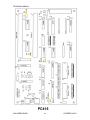
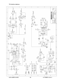
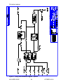
PC416 Function (Solenoid valve driver and Status I/O board)
This PCB is used to activate the solenoid valves used to isolate the gases on the
input gas ports. These valves are turned on with 24 VDC and then run at 30% duty
cycle or 1/3 power. This allows more efficient use of the internal 24 VDC power
supply. This board also controls the input and output status lines.
To use the Status Input feature, the 2 control pins for the desired status input must be
connected together. The status input signal must be present for at least 500
milliseconds to ensure that the connection is properly detected by the software.
Caution: The status inputs respond only to a connection between adjacent
pins of the desired input. Do not apply any voltage to the status input pins, as
this will result in damage to the instrument
To use a Status Output to provide a “contact” output, connect the inputs for the
device being controlled to the desired STATUS OUTPUT pin, and to GROUND.
To use a Status Output to provide a “powered” 24 volt output (to drive a relay for
example), connect the inputs for the device being controlled to the desired STATUS
OUTPUT pin, and to +24 VOLTS.
Reference user’s guide for more detailed instructions on the setup and operation of
the status I/O lines.
Caution: Each status output can sink a maximum of 100 mA. Do not connect
anything to the outputs (such as a solenoid valve) that will draw more than 100
mA, as this will result in damage to the instrument
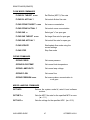
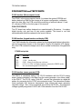
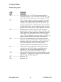
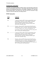
PC416 test points
TP#
VALUE
TP1(+5)
5 VDC Steady state
TP2(GND)
GND meter reference for TP1.
TP3(100KHZ)
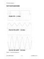
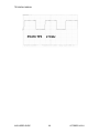
See PC416 TP3 diagram on page 67 for waveform.
TP4(PGND)
This is the power (+24VDC) ground test point for the negative
(black) meter lead when measuring the +24 VDC test point TP5.
TP5(+24)
+24 VDC steady state.
( ) VALUES IN PARENTHESIS ARE AS SEEN ON THE PCB SILKSCREEN.
6100 USER’S GUIDE
66
OCTOBER 14 2011