1
Keysight N8975A
Option K40
Blockdown Converter
Operating and
Service Manual
Special
Supplement
Notices
© Keysight Technologies, Inc.
2007-2015
COVERING THE MATERIAL IN THIS
DOCUMENT THAT CONFLICT WITH
THESE TERMS, THE WARRANTY
TERMS IN THE SEPARATE
AGREEMENT WILL CONTROL.
No part of this manual may be
reproduced in any form or by any
means (including electronic storage
and retrieval or translation into a
foreign language) without prior
agreement and written consent from
Keysight Technologies, Inc. as
governed by United States and
international copyright laws.
Technology Licenses
Trademark Acknowledgments
The Software is “commercial
computer software,” as defined
by Federal Acquisition Regulation
(“FAR”) 2.101. Pursuant to FAR
12.212 and 27.405-3 and
Department of Defense FAR
Supplement (“DFARS”) 227.7202,
the U.S. government acquires
commercial computer software
under the same terms by which
the software is customarily
provided to the public.
Accordingly, Keysight provides
the Software to U.S. government
customers under its standard
commercial license, which is
embodied in its End User License
Agreement (EULA), a copy of
which can be found at
http://www.keysight.com/find/sweula
The license set forth in the EULA
represents the exclusive authority
by which the U.S. government
may use, modify, distribute, or
disclose the Software. The EULA
and the license set forth therein,
does not require or permit,
among other things, that
Keysight: (1) Furnish technical
information related to
commercial computer software
or commercial computer
software documentation that is
not customarily provided to the
public; or (2) Relinquish to, or
otherwise provide, the
government rights in excess of
these rights customarily provided
to the public to use, modify,
reproduce, release, perform,
display, or disclose commercial
computer software or
commercial computer software
Manual Part Number
N8975-90002
Edition
Edition 1, July 2015
Supersedes: March 2015
Printed in USA/Malaysia
Published by:
Keysight Technologies
1400 Fountaingrove Parkway
Santa Rosa, CA 95403
Warranty
THE MATERIAL CONTAINED IN THIS
DOCUMENT IS PROVIDED “AS IS,”
AND IS SUBJECT TO BEING
CHANGED, WITHOUT NOTICE, IN
FUTURE EDITIONS. FURTHER, TO
THE MAXIMUM EXTENT PERMITTED
BY APPLICABLE LAW, KEYSIGHT
DISCLAIMS ALL WARRANTIES,
EITHER EXPRESS OR IMPLIED WITH
REGARD TO THIS MANUAL AND
ANY INFORMATION CONTAINED
HEREIN, INCLUDING BUT NOT
LIMITED TO THE IMPLIED
WARRANTIES OF
MERCHANTABILITY AND FITNESS
FOR A PARTICULAR PURPOSE.
KEYSIGHT SHALL NOT BE LIABLE
FOR ERRORS OR FOR INCIDENTAL
OR CONSEQUENTIAL DAMAGES IN
CONNECTION WITH THE
FURNISHING, USE, OR
PERFORMANCE OF THIS
DOCUMENT OR ANY INFORMATION
CONTAINED HEREIN. SHOULD
KEYSIGHT AND THE USER HAVE A
SEPARATE WRITTEN AGREEMENT
WITH WARRANTY TERMS
The hardware and/or software
described in this document are
furnished under a license and may be
used or copied only in accordance
with the terms of such license.
U.S. Government Rights
documentation. No additional
government requirements
beyond those set forth in the
EULA shall apply, except to the
extent that those terms, rights, or
licenses are explicitly required
from all providers of commercial
computer software pursuant to
the FAR and the DFARS and are
set forth specifically in writing
elsewhere in the EULA. Keysight
shall be under no obligation to
update, revise or otherwise
modify the Software. With
respect to any technical data as
defined by FAR 2.101, pursuant
to FAR 12.211 and 27.404.2 and
DFARS 227.7102, the U.S.
government acquires no greater
than Limited Rights as defined in
FAR 27.401 or DFAR 227.7103-5
(c), as applicable in any technical
data.
Safety Notices
A CAUTION notice denotes a hazard. It
calls attention to an operating
procedure, practice, or the like that,
if not correctly performed or adhered
to, could result in damage to the
product or loss of important data. Do
not proceed beyond a CAUTION
notice until the indicated conditions
are fully understood and met.
A WARNING notice denotes a hazard.
It calls attention to an operating
procedure, practice, or the like that,
if not correctly performed or adhered
to, could result in personal injury or
death. Do not proceed beyond a
WARNING notice until the indicated
conditions are fully understood and
met.
Where to Find the Latest Information
Documentation is updated periodically. For the latest information about these products, including instrument software
upgrades, application information, and product information, browse to one of the following URLs, according to the name
of your product:
http://www.keysight.com/find/n8975a
To receive the latest updates by email, subscribe to Keysight Email Updates at the following URL:
http://www.keysight.com/find/MyKeysight
Information on preventing instrument damage can be found at:
www.keysight.com/find/PreventingInstrumentRepair
Is your product software up-to-date?
Periodically, Keysight releases software updates to fix known defects and incorporate product enhancements. To search
for software updates for your product, go to the Keysight Technical Support website at:
http://www.keysight.com/find/techsupport
3
4
Contents
Table of Contents
1.
General Information
Section 1.01 Introduction . . . . . . . . . . . . . . . . . . . . . . . . . . . . . . . . . . . . . . . . . . . . . . . . . . . . . . . . . . . . . . . . . . . . . . . 7
Section 1.02 Specifications . . . . . . . . . . . . . . . . . . . . . . . . . . . . . . . . . . . . . . . . . . . . . . . . . . . . . . . . . . . . . . . . . . . . . 7
Section 1.03 Safety Consideration . . . . . . . . . . . . . . . . . . . . . . . . . . . . . . . . . . . . . . . . . . . . . . . . . . . . . . . . . . . . . . . . 8
Section 1.04 Description. . . . . . . . . . . . . . . . . . . . . . . . . . . . . . . . . . . . . . . . . . . . . . . . . . . . . . . . . . . . . . . . . . . . . . . . 9
Section 1.05 Options. . . . . . . . . . . . . . . . . . . . . . . . . . . . . . . . . . . . . . . . . . . . . . . . . . . . . . . . . . . . . . . . . . . . . . . . . . . 9
Section 1.06 Accessories Supplied. . . . . . . . . . . . . . . . . . . . . . . . . . . . . . . . . . . . . . . . . . . . . . . . . . . . . . . . . . . . . . . . 9
Section 1.07 Equipment Required but not Supplied . . . . . . . . . . . . . . . . . . . . . . . . . . . . . . . . . . . . . . . . . . . . . . . . . 10
Section 1.08 Electrical Equipment Available . . . . . . . . . . . . . . . . . . . . . . . . . . . . . . . . . . . . . . . . . . . . . . . . . . . . . . . 10
Section 1.09 Chassis Slide Mount Kit. . . . . . . . . . . . . . . . . . . . . . . . . . . . . . . . . . . . . . . . . . . . . . . . . . . . . . . . . . . . . 10
Section 1.10 Recommended Test Equipment . . . . . . . . . . . . . . . . . . . . . . . . . . . . . . . . . . . . . . . . . . . . . . . . . . . . . . 10
Section 1.11 Symbols and Labels. . . . . . . . . . . . . . . . . . . . . . . . . . . . . . . . . . . . . . . . . . . . . . . . . . . . . . . . . . . . . . . . 11
2.
Installation
Section 2.01 Introduction . . . . . . . . . . . . . . . . . . . . . . . . . . . . . . . . . . . . . . . . . . . . . . . . . . . . . . . . . . . . . . . . . . . . . . 13
Section 2.02 Initial Inspection . . . . . . . . . . . . . . . . . . . . . . . . . . . . . . . . . . . . . . . . . . . . . . . . . . . . . . . . . . . . . . . . . . 13
Section 2.03 Power Requirements . . . . . . . . . . . . . . . . . . . . . . . . . . . . . . . . . . . . . . . . . . . . . . . . . . . . . . . . . . . . . . . 14
Section 2.04 Line Voltage and Fuse Selection. . . . . . . . . . . . . . . . . . . . . . . . . . . . . . . . . . . . . . . . . . . . . . . . . . . . . . 14
Section 2.05 Power Cables. . . . . . . . . . . . . . . . . . . . . . . . . . . . . . . . . . . . . . . . . . . . . . . . . . . . . . . . . . . . . . . . . . . . . 14
Section 2.06 Mating Connectors . . . . . . . . . . . . . . . . . . . . . . . . . . . . . . . . . . . . . . . . . . . . . . . . . . . . . . . . . . . . . . . . 15
Section 2.07 Operating Environment . . . . . . . . . . . . . . . . . . . . . . . . . . . . . . . . . . . . . . . . . . . . . . . . . . . . . . . . . . . . . 16
Section 2.08 Bench Operation . . . . . . . . . . . . . . . . . . . . . . . . . . . . . . . . . . . . . . . . . . . . . . . . . . . . . . . . . . . . . . . . . . 16
Section 2.09 Rack Mounting . . . . . . . . . . . . . . . . . . . . . . . . . . . . . . . . . . . . . . . . . . . . . . . . . . . . . . . . . . . . . . . . . . . 16
Section 2.10 Storage and Shipment Environment. . . . . . . . . . . . . . . . . . . . . . . . . . . . . . . . . . . . . . . . . . . . . . . . . . . 16
Section 2.11 Packaging . . . . . . . . . . . . . . . . . . . . . . . . . . . . . . . . . . . . . . . . . . . . . . . . . . . . . . . . . . . . . . . . . . . . . . . 17
3.
Operation
Section 3.01 Introduction . . . . . . . . . . . . . . . . . . . . . . . . . . . . . . . . . . . . . . . . . . . . . . . . . . . . . . . . . . . . . . . . . . . . . . 19
Section 3.02 Panel Features . . . . . . . . . . . . . . . . . . . . . . . . . . . . . . . . . . . . . . . . . . . . . . . . . . . . . . . . . . . . . . . . . . . . 19
Section 3.03 Front Panel Features . . . . . . . . . . . . . . . . . . . . . . . . . . . . . . . . . . . . . . . . . . . . . . . . . . . . . . . . . . . . . . . 19
Section 3.04 Rear Panel Features . . . . . . . . . . . . . . . . . . . . . . . . . . . . . . . . . . . . . . . . . . . . . . . . . . . . . . . . . . . . . . . 20
Section 3.05 Operating Characteristics . . . . . . . . . . . . . . . . . . . . . . . . . . . . . . . . . . . . . . . . . . . . . . . . . . . . . . . . . . . 20
Section 3.06 Operator's Maintenance . . . . . . . . . . . . . . . . . . . . . . . . . . . . . . . . . . . . . . . . . . . . . . . . . . . . . . . . . . . . 20
Section 3.07 General Operating Instructions . . . . . . . . . . . . . . . . . . . . . . . . . . . . . . . . . . . . . . . . . . . . . . . . . . . . . . . 22
Section 3.08 Turn-On Procedure . . . . . . . . . . . . . . . . . . . . . . . . . . . . . . . . . . . . . . . . . . . . . . . . . . . . . . . . . . . . . . . . 22
Section 3.09 Down Converter Operation . . . . . . . . . . . . . . . . . . . . . . . . . . . . . . . . . . . . . . . . . . . . . . . . . . . . . . . . . . 22
Section 3.10 Setup and Calibration Procedure . . . . . . . . . . . . . . . . . . . . . . . . . . . . . . . . . . . . . . . . . . . . . . . . . . . . . 23
Section 3.11 Sales and Service Offices . . . . . . . . . . . . . . . . . . . . . . . . . . . . . . . . . . . . . . . . . . . . . . . . . . . . . . . . . . . 24
4.
Performance Tests
5
Contents
Section 4.01 Introduction . . . . . . . . . . . . . . . . . . . . . . . . . . . . . . . . . . . . . . . . . . . . . . . . . . . . . . . . . . . . . . . . . . . . . . 25
Section 4.02 Equipment Required . . . . . . . . . . . . . . . . . . . . . . . . . . . . . . . . . . . . . . . . . . . . . . . . . . . . . . . . . . . . . . . 25
Section 4.03 Performance Test Record . . . . . . . . . . . . . . . . . . . . . . . . . . . . . . . . . . . . . . . . . . . . . . . . . . . . . . . . . . . 25
Section 4.04 Calibration Cycle . . . . . . . . . . . . . . . . . . . . . . . . . . . . . . . . . . . . . . . . . . . . . . . . . . . . . . . . . . . . . . . . . . 25
Section 4.05 Performance Test Procedures . . . . . . . . . . . . . . . . . . . . . . . . . . . . . . . . . . . . . . . . . . . . . . . . . . . . . . . . 26
Section 4.06 Frequency Range and Noise Figure . . . . . . . . . . . . . . . . . . . . . . . . . . . . . . . . . . . . . . . . . . . . . . . . . . . 26
Section 4.07 LO Frequency Accuracy . . . . . . . . . . . . . . . . . . . . . . . . . . . . . . . . . . . . . . . . . . . . . . . . . . . . . . . . . . . . 29
5.
Adjustments
6.
Service
Section 6.01 Introduction . . . . . . . . . . . . . . . . . . . . . . . . . . . . . . . . . . . . . . . . . . . . . . . . . . . . . . . . . . . . . . . . . . . . . . 33
Section 6.02 Service Sheets. . . . . . . . . . . . . . . . . . . . . . . . . . . . . . . . . . . . . . . . . . . . . . . . . . . . . . . . . . . . . . . . . . . . 33
Section 6.03 Safety Considerations . . . . . . . . . . . . . . . . . . . . . . . . . . . . . . . . . . . . . . . . . . . . . . . . . . . . . . . . . . . . . . 33
Section 6.04 Servicing the Instrument. . . . . . . . . . . . . . . . . . . . . . . . . . . . . . . . . . . . . . . . . . . . . . . . . . . . . . . . . . . . 34
Section 6.05 Pozidrive Screwdrivers . . . . . . . . . . . . . . . . . . . . . . . . . . . . . . . . . . . . . . . . . . . . . . . . . . . . . . . . . . . . . 35
Section 6.06 Hardware . . . . . . . . . . . . . . . . . . . . . . . . . . . . . . . . . . . . . . . . . . . . . . . . . . . . . . . . . . . . . . . . . . . . . . . . 35
Section 6.07 Assembly Locations. . . . . . . . . . . . . . . . . . . . . . . . . . . . . . . . . . . . . . . . . . . . . . . . . . . . . . . . . . . . . . . . 35
Section 6.08 Parts and Cable Locations . . . . . . . . . . . . . . . . . . . . . . . . . . . . . . . . . . . . . . . . . . . . . . . . . . . . . . . . . . 35
Section 6.09 Test Point Locations . . . . . . . . . . . . . . . . . . . . . . . . . . . . . . . . . . . . . . . . . . . . . . . . . . . . . . . . . . . . . . . 35
Section 6.10 Cover Removal . . . . . . . . . . . . . . . . . . . . . . . . . . . . . . . . . . . . . . . . . . . . . . . . . . . . . . . . . . . . . . . . . . . 36
Section 6.11 Cleaning Intervals . . . . . . . . . . . . . . . . . . . . . . . . . . . . . . . . . . . . . . . . . . . . . . . . . . . . . . . . . . . . . . . . . 36
Section 6.12 Six Month Cleaning . . . . . . . . . . . . . . . . . . . . . . . . . . . . . . . . . . . . . . . . . . . . . . . . . . . . . . . . . . . . . . . . 36
Section 6.13 Twelve Month Cleaning . . . . . . . . . . . . . . . . . . . . . . . . . . . . . . . . . . . . . . . . . . . . . . . . . . . . . . . . . . . . . 37
Section 6.14 Overall Troubleshooting . . . . . . . . . . . . . . . . . . . . . . . . . . . . . . . . . . . . . . . . . . . . . . . . . . . . . . . . . . . . 37
Section 6.15 Principles of Operation . . . . . . . . . . . . . . . . . . . . . . . . . . . . . . . . . . . . . . . . . . . . . . . . . . . . . . . . . . . . . 38
Section 6.16 Troubleshooting. . . . . . . . . . . . . . . . . . . . . . . . . . . . . . . . . . . . . . . . . . . . . . . . . . . . . . . . . . . . . . . . . . . 38
Section 6.17 Check List . . . . . . . . . . . . . . . . . . . . . . . . . . . . . . . . . . . . . . . . . . . . . . . . . . . . . . . . . . . . . . . . . . . . . . . 38
7.
Operating the Down Converter with the 8970B/8971C NF System
8.
Service Replaceable Parts
Section 8.01 Introduction . . . . . . . . . . . . . . . . . . . . . . . . . . . . . . . . . . . . . . . . . . . . . . . . . . . . . . . . . . . . . . . . . . . . . . 45
Section 8.02 Accessories . . . . . . . . . . . . . . . . . . . . . . . . . . . . . . . . . . . . . . . . . . . . . . . . . . . . . . . . . . . . . . . . . . . . . . 45
6
Keysight N8975A Option K40
Blockdown Converter
Operating and Service Manual Special Supplement
1
General Information
Section 1.01 Introduction
This Operating and Service Manual contains information required to install,
operate, test and service the Model N8975A Option K40 Block Down
Converter. Throughout this manual the Model N8975A Option K40 will also be
referred to as the Down Converter.
The Down Converter Operating and Service Manual has eight sections
consisting of:
— Section 1 General Information
— Section 2 Installation
— Section 3 Operation
— Section 4 Performance Tests
— Section 5 Adjustments
— Section 6 Service
— Section 7 Operating the Down Converter with the 8970B/8971C NF
System
— Section 8 Service Replaceable Parts
Section 1.02 Specifications
Instrument specifications for the Down Converter are listed in Table 1-1. These
specifications are the performance standards against which the instrument
may be tested. Supplemental characteristics are listed in Table 1-2.
Supplemental characteristics are not warranted specifications, but are typical
characteristics included as additional information for the user.
Table 1-1
Specifications
Characteristics
Performance Limits
Input Frequency
26.5 - 40 GHz
Output Frequency
18 - 4.5 GHz
7
Cond itions
General Information
Section 1.03 Safety Consideration
Table 1-1
Specifications
Characteristics
Performance Limits
LO Frequency
44.5 GHz ± 50 MHz
Noise Figure
20 dB Maximum <15 dBm Typ
Cond itions
Temperature Range
Table 1-2
Specification Range
15° to 35 °C
Operating Range
0 to 50 °C
Storage
-40° to +70 °C
Supplemental Characteristics
Characteristics
Performance Limits
Cond itions
Conversion Gain
18 dB Nominal
@33 GHz
Humidity
20 - 80% R.H.
@40 °C
Altitude
2000 Meters MAX (6562ft)
Power Consumption
70 VA Max.
50 - 60Hz
100-240V AC
Dimensions
88.5mm H x 212.6mm W x 348.3mm D
Weight
Net 4.5 Kg (9.9 lbs)
Excluding front and rear
panel protrusions
Shipping 8.4 Kg (18.5 lbs)
This instrument is designed for use in an Installation Category II and Pollution
Degree 2 environment, per IEC 61010.
Section 1.03 Safety Consideration
This instrument has been designed and tested in accordance with IEC
publication 61010-1:2001, Safety Requirements for Electrical Equipment for
Measurement, Control, and Laboratory Use, and has been supplied in a safe
condition. The instruction documentation contains information and warnings
that must be followed by the user to ensure safe operation and to maintain the
instrument in a safe condition.
8
Chapter 1
General Information
Section 1.04 Description
This is a safety Class 1 product (provided with a protective earthing ground
incorporated in the power cord). The mains plug shall only be inserted in a socket
outlet provided with a protective earth contact. Any interruption of the protective
conductor inside or outside the instrument is likely to make the instrument
dangerous. Intentional interruption is prohibited.
Section 1.04 Description
The N8975A Option K40 Block Down Converter is designed to be used with the
N8975A Noise Figure Analyzer. The option K40 extends the frequency range of
the N8975A by down converting the 26.5 GHz to 40 GHz frequency band. In
addition to the N8975A a Noise Source (346C K01 recommended) is required
for a complete Noise Figure measurement system.
The Down Converter uses an internal 44.5 GHz LO for down conversion of the
26.5 GHz to 40 GHz input. The resulting 18 GHz to 4.5 GHz signal is processed
by the N8975A Noise Figure Analyzer to give information about the noise figure
and gain of a Device Under Test (DUT).
Section 1.05 Options
There are no electrical or mechanical options to the N8975A option K40 Down
Converter.
Section 1.06 Accessories Supplied
The N8975A option K40 Down Converter is supplied with a three wire power
cable. Different cables are available for different power mains configurations.
Check with you local Keysight Technologies office for descriptions and part
numbers for these cables.
A rack mount kit is supplied for mounting the N8975A option K40 in a standard
19 inch EIA rack. The part number for the rack mount kit is 5063-9240.
An RF cable, part number 08971-60127 is supplied. This cable is used to
connect the Down Converter RF OUTPUT to the N8975A INPUT.
An APC 2.4 mm female to female coax adapter is supplied (part number
1250-2188). This is supplied to connect the 346C K01 to the Down Converter
RF Input for calibration.
Chapter 1
9
General Information
Section 1.07 Equipment Required but not Supplied
Section 1.07 Equipment Required but not Supplied
To form a noise figure measurement system for measurements in the 26.5 to
40 GHz band the additional equipment required:
— N8975A Noise Figure Analyzer
— 346C K01 Noise Source
Section 1.08 Electrical Equipment Available
Waveguide/Coax Adapters R281A WR28 to 2.4mm APC
Waveguide Noise Source R347B 26.5 to 40GHz
Section 1.09 Chassis Slide Mount Kit
This kit is used to install one or more instruments in a sliding support shelf,
Order shelf part number 5063-9255, and slide kit 1494-0015 (for a single
instrument, also order filler panel 5002-3999).
Section 1.10 Recommended Test Equipment
Table 1-3 lists the test equipment recommended for use in testing, adjusting
and servicing the Down Converter. The Critical Specification column describes
the essential requirement for each piece of test equipment. Other equipment
may be substituted if it meets or exceeds the critical specifications.
The recommended model column may suggest more than one model. The first
model shown is usually the least expensive, single-purpose model. Alternate
models are suggested, with additional features, that would be a better choice
in some applications.
Table 1-3
10
Recommended Test Equipment
Instrument
Critical Specification
Recommended Model
Noise Figure Analyzer
Noise Figure
Measurements 4.5-18 GHz
N8975A (or 8970S)
Synthesizer
26.5 - 40 GHz 0 dBm
83640A
Noise Source
ENR >9dB 10 MHz - 40 GHz
346C #K01
Spectrum Analyzer
Signal Analysis 2-18 GHz
E4407B, 8566A/B
Coaxial Adapter
APC 2.4mm female to
3.5mm female
1250-2277
Chapter 1
General Information
Section 1.11 Symbols and Labels
Section 1.11 Symbols and Labels
The Caution, risk of danger symbol. The product is marked with this
symbol when it is necessary for the user to refer to the instructions in the
supplied documentation.
The out position of a bistable push control switch.
The in position of a bistable push control switch.
The ON/OFF symbol.
The ON symbol.
Indicates a Protective Conductor Terminal that must be connected to
earth ground before operating the equipment protects against electrical
shock in case of a fault.
Warning denotes a hazard. It calls attention to a procedure which, if not
correctly performed or adhered to, could result in injury or loss of life. Do
not proceed beyond a warning note until indicated conditions are fully
understood and met.
Caution denotes a hazard. It calls attention to a procedure which, if not
correctly performed or adhered to, could result in damage to or
destruction of the instrument. Do not proceed beyond a caution note until
the indicated conditions are fully understood and met.
This ISM device complies with Canadian ICES-001. Cet appareil ISM est
conforme à la norme NMB-001 du Canada.
The Caution, risk of danger symbol. The product is marked with this
symbol when it is necessary for the user to refer to the instructions in the
supplied documentation.
The CE mark shows that the product complies with all applicable
European Directives.
Chapter 1
11
General Information
Section 1.11 Symbols and Labels
The CSA mark is a registered trademark of the Canadian Standards
Association.
The C-Tick mark is a registered trademark of the Australian
Communications Authority. This signifies compliance with the Australian
EMC Framework Regulations under the terms of the Radio
Communications Act of 1992.
This is the symbol for an Industrial, Scientific and Medical, Group 1 Class
product.
This symbol indicates separate collection for electrical and electronic
equipment, mandated under EU law as of August 13, 2005. All electric
and electronic equipment are required to be separated from normal waste
for disposal (Reference WEEE Directive, 2002/96/EC)
This symbol not only indicates the presence of hazardous or toxic
substances above the MCV, but also specifies that the material/product is
recyclable and should not be "thrown away casually", as well as the length
of the environmental protection use period EPUP (Environmental
Protection Use Period) is stated in the number of years, starting with the
date of manufacture, located in the center of the symbol.
This equipment is Class A suitable for professional use and is for use in
electromagnetic environments outside of the home.
12
Chapter 1
Keysight N8975A Option K40
Blockdown Converter
Operating and Service Manual Special Supplement
2
Installation
Section 2.01 Introduction
This section provides the information needed to install the N8975A option K40
Down Converter. Included is information pertinent to initial inspection, power
requirements, line voltage selection, power cables, interconnection,
environment, storage and shipment.
If this instrument is not used as specified, the protection provided by the
equipment could be impaired. This instrument must be used in a normal condition
(in which all means for protection are intact) only.
Appliance Coupler (mains input powercord) is the power disconnect device. Do
not position the instrument such that access to the coupler is impaired.
Section 2.02 Initial Inspection
To avoid hazardous electrical shock, do not perform electrical tests when there are
signs of shipping damage to any portion of the outer enclosure (covers, panels,
connectors).
Inspect the shipping container for damage. If the shipping container or
cushioning material is damaged, it should be kept until the contents of the
shipment have been checked for completeness and the instrument has been
checked mechanically and electrically. The contents of the shipment should
include the accessories specified in “Section 1.06 Accessories Supplied” on
page 9. Procedures for checking electrical performance are given in Chapter 4,
“Performance Tests”, on page 25. If the contents are incomplete or if there is
mechanical damage or defect notify the nearest Keysight Technologies office.
If the shipping container is damaged, or the cushioning material shows signs of
stress, notify the carrier as well as the Keysight Technologies office. Keep the
shipping material for carrier's inspection.
13
Installation
Section 2.03 Power Requirements
Section 2.03 Power Requirements
The N8975A Option K40 Down Converter requires a power source of between
100V AC to 240 V AC single phase. Line frequency is 50-60Hz. The rated power
consumption is 100V AC 45VA and 240V AC 70VA maximum.
This is a safety class 1 product (that is, provided with a protective earth
terminal). An un-interruptable safety earth ground must be provided from
the main power source to the product input wiring terminals, power cord
or supplied power cord set.
Whenever it is likely that the protection has been impaired, the product
must be made inoperative and be secured against any unintended
operation.
Section 2.04 Line Voltage and Fuse Selection
This instrument has an autoranging line voltage input, be sure the supply voltage
is within the specified range. The mains supply voltage fluctuations are not to
exceed ±10% of the nominal supply voltage.
The Down Converter will operate with voltages between 100V AC and 240V AC
and so requires no switching or change of fuse.
Section 2.05 Power Cables
Before connecting this instrument, the protective earth terminals of this
instrument must be connected to the protective conductor of the line (Mains)
power cable. The line plug shall only be inserted in a socket outlet provided with a
protective earth contact. The protective action must not be negated by the use of
an extension cord (power cable) without a protective conductor (grounding).
Grounding one conductor of a two conductor outlet is not sufficient protection.
This instrument is equipped with a three-wire power cable. When connected to
an appropriate AC power receptacle, this cable grounds the instrument
cabinet. The type of power cable plug shipped with each instrument depends
on the country of destination. See Figure 2-1 Power Cable and Line (Mains)
Plug part numbers, for the part numbers of available power cables. Cables are
14
Chapter 2
Installation
Section 2.06 Mating Connectors
available in different lengths or with right angle plugs to the instrument. Check
with your nearest Keysight Technologies service center for descriptions and
part numbers of these cables.
External Protective Earth Terminal
While this is a Class I product, provided with a protective earthing conductor in
a power cord, an external protective earthing terminal has also been provided.
This terminal is for use where the earthing cannot be assured. At least an
18AWG earthing conductor should be used in such an instance, to ground the
instrument to an assured earth terminal.
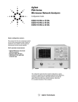
Figure 2-1
Power Cable and Mains Plug Part Numbers
Section 2.06 Mating Connectors
Mating connectors used with the Down Converter are 50Ω, 2.4mm APC male
RF INPUT connector and a 50Ω, 3.5mm APC male RF OUTPUT connector
located on the front panel. Mating connectors used with the Down Converter
should be of the same type and US MIL-C-39012 compatible.
Chapter 2
15
Installation
Section 2.07 Operating Environment
Section 2.07 Operating Environment
The operating environment for the Down Converter should be maintained
within the following limitations:
Specified Temperature Range
15 °C to 35 °C
Operating temperature range
0 °C to 50 °C
Humidity
20% to 80% RH @40 °C
Altitude
<2000 meters (6562 feet)
For indoor use only.
VENTILATION REQUIREMENTS When installing the instrument in a cabinet, the
convection into and out of the instrument must not be restricted. The ambient
temperature (outside the cabinet) must be lest than the maximum operating
temperature of the instrument by 4 °C for every 100 Watts dissipated in the
cabinet. If the total power dissipated in the cabinet is greater then 800 Watts,
then forced convection must be used.
Section 2.08 Bench Operation
The instrument has rubber feet for convenience in bench operation.
Section 2.09 Rack Mounting
Rack mounting information is provided with the rack mount kit that is supplied
with the instrument.
Section 2.10 Storage and Shipment Environment
The instrument should be stored in a clean, dry environment. The following
environment limitations apply to both storage and shipment:limitations:
16
Temperature
-40 °C to +70 °C
Humidity
<95% relative
Altitude
<15,300 Meters (50,000 feet)
Chapter 2
Installation
Section 2.11 Packaging
Section 2.11 Packaging
The instrument should be stored in a clean, dry environment. The following
environment limitations apply to both storage and shipment limitations:
Tagging for Service
If the instrument is being returned to Keysight Technologies for service, please
complete one of the blue repair tags located at the end of any Service manual,
and attach to the instrument.
Original Packaging:
Containers and materials identical to those used in factory packaging are
available through Keysight Technologies offices. Mark the container "FRAGILE"
to assure careful handling. In any correspondence refer to the instrument by
model number and full serial number.
Other Packing:
The following general instructions should be used for re-packaging with
commercially available materials:
— Wrap the instrument in heavy paper or plastic. If shipping to a Keysight
Technologies office or service center, attach a tag indicating the type of
service required, return address, model number, and full serial number (use
blue repair tag).
— Use a strong shipping container. A double wall carton made of 2.4 MPa
(350 psi) test material is adequate.
— Use enough shock absorbing material 75 to 100mm (3 to 4 inches) thick
around all sides of the instrument to provide a firm cushion and prevent
movement in the container.
— Protect the front panel with an appropriate type of cushioning material to
prevent damage during shipment.
— Seal the container.
— Mark the container "FRAGILE" to assure careful handling.
— In any correspondence, refer to the instrument by model number and full
serial number.
Chapter 2
17
Installation
Section 2.11 Packaging
18
Chapter 2
Keysight N8975A Option K40
Blockdown Converter
Operating and Service Manual Special Supplement
3
Operation
Section 3.01 Introduction
This section provides complete operating information for the Down Converter.
Included in this section are descriptions of the front and rear panel connectors
and indicators, maintenance, and operating instructions.
When using the Down Converter with a N8975A Noise Figure Analyzer, refer to
the N8975A Operating and Service Manual for additional operating
information.
When using the Down Converter with the 8970B/8971C noise figure system a
20 dB attenuator connected to the output of the Down Converter is required so
that the nominal gain of the Down Converter plus attenuator is approximately
0 dB.
Section 3.02 Panel Features
The front and rear panel features are shown in Figure 3-1.
Any explanation of all connectors and indicators is given in Section 3.03 Front
Panel Features and Section 3.04 Rear Panel Features.
Section 3.03 Front Panel Features
a. RF Input (J1)
A 2.4mm female connector provides the input to the Down Converter. The
maximum input to avoid damage, when used with an N8975A Noise Figure
Meter, is +10 dBm. The impedance is 50Ω. Generally, the noise source is
attached to this connector for calibration, and the device under test is
attached to this connector for noise figure measurement.
b. RF Output (J2)
19
Operation
Section 3.04 Rear Panel Features
A 3.5 mm male connector provides the down converted output to the
N8975A. Signals of 26.5 GHz to 40 GHz at the RF INPUT are mixed with a
fixed 44.5 GHz LO in the N8975A option K40 to produce the down
converted 18 GHz to 4.5 GHz output.
The LOWER SIDEBAND is down converted.
c. Power (S1)
This switch turns the instrument power supply between stand-by and on.
When it is in the ON (1) position the instrument is operational.
Section 3.04 Rear Panel Features
a. Power (MP1)
Line power module connects the power cord to the Down Converter and
contains the line over current protection fuse. Center conductor is a
chassis connection for safety earth ground.
b. Fuse
An F3.15AH fuse is installed for all voltage supplies.
Section 3.05 Operating Characteristics
The Down Converter, when used with N8975A Noise Figure Analyzer, extends
the frequency up into the 26.5-40 GHz band.
Down Converter Performance Specifications and Supplemental Characteristics
are contained in Table 1-1 and Table 1-2.
Section 3.06 Operator's Maintenance
For continued protection against fire hazard, replace the line fuse only with the
same type and rating (F3.15AH, 250V). The use of other fuses or materials is
prohibited.
Replacing a defective primary fuse, Keysight Part Number 2110-0957. This
fuse is located in the line module assembly.
20
Chapter 3
Operation
Section 3.06 Operator's Maintenance
Clean the cabinet, Using a damp cloth only.
No Operator serviceable parts inside. Refer servicing to qualified personnel. To
prevent electric shock do not remove covers.
Figure 3-1
Chapter 3
Front and Rear Panel
21
Operation
Section 3.07 General Operating Instructions
Figure 3-2
Test Set-up for Calibration and Measurement of Noise Figure
Section 3.07 General Operating Instructions
Before the instrument is switched on, all protective earth terminals, extension
cords, auto transformers, and devices connected to the instrument should be
connected to a protective earth grounded socket. Any interruption of the
protective earth grounding will cause a potential shock hazard that could result in
personal injury.
Section 3.08 Turn-On Procedure
If the Down Converter is not plugged in, follow these instructions:
1. Check the line voltage is correct to operate the Down Converter.
2. Plug in the power cable.
3. Press the line switch on the front panel to ON.
Section 3.09 Down Converter Operation
The Down Converter require to be operated with a N8975A Noise Figure
Analyzer for a complete 26.5 GHz to 40 GHz noise figure measurement system.
As an example, the following procedure would be used to calibrate and
measure the noise figure and gain of an amplifier from 26.5 GHz to 40 GHz
every 500 MHz.
22
Chapter 3
Operation
Section 3.10 Setup and Calibration Procedure
i. ENR Data
Before noise figure and gain measurements can be made, the ENR of the
Noise Source must be entered into the N8975A. Information on how to
enter the data is found in the ENR Table Entry procedure in Chapter 2 in
the section on "Entering Excess Noise Ratio Data" of the N8975A Users
Guide(N8972-90080). It is not necessary to input all ENR data points, but
the data must cover the measurement frequency.
ii. Connections - Calibration
To calibrate the N8975A and the K40 Down Converter as a system make
the following connections as shown in Figure 3-2:
— Connect 346C K01 Noise Source to the K40 RF INPUT using adapter
1250-2188.
— Connect the K40 RF OUTPUT to the N8975A INPUT using cable
08971-60127.
— Connect the N8975A Noise Source Drive Output to the 346C K01
INPUT.
Section 3.10 Setup and Calibration Procedure
1. Switch on the N8975A and the K40 Down Converter allow half an hour to
warm up.
2. Press [System] then softkey {External LO} then {Max Freq} and enter
[5] [0] {GHz}.
3. Press key [Meas Mode] then softkey {Amplifier} then key [Tab→].
4. Press Sys Downconv softkey {On}. Note LO Mode should be "Fixed".
5. Press key [Mode Setup]. Note LO Frequency should be highlighted, if not
press [Tab→] key until it is.
6. Enter using numeric keys [4] [4] [.] [5] then softkey {GHz}. Note IF
Frequency is blank, Sideband should be LSB, LO Control should be Off. If
not use the [Tab→] key to highlight the parameter to change and then
press the appropriate softkey.
7. Press key [Frequency/Points] then softkey {Start Freq} and enter [2] [6] [.]
[5] {GHz} then softkey {Stop Freq} and enter [4] [0] {GHz}.
8. Press softkey {More 1 of 2} then softkey {Points} and enter [2] [8] [Enter].
9. Press [System] then softkey {Alignment} then softkey {Alignmnt Mode} to
Point.
Alignment should be ON.
Chapter 3
23
Operation
Section 3.11 Sales and Service Offices
10.Press key [Averaging/Bandwidth] then softkey {Averages} and enter [3]
[2] [Enter]. Press softkey {Averaging} to On.
11.Press [Calibrate] twice and wait for calibration to complete.
i. Measurement Procedure
After calibration disconnect the noise source from the RF INPUT of
the K40 Down Converter. Connect the noise source output to the
input of the device under test (DUT) and the output of the DUT to
the K40 Down Converter RF INPUT. Press [Restart] and wait for the
measurement sweep to complete. Record the results.
For the Noise Figure Measurement System specifications to be valid, the
measurement must use the same START FREQ, STOP FREQ and STEP SIZE that
was used for calibration. None of the calibrated points can be skipped. Also, the
measurement must be done in the same direction as the calibration, for example,
from start frequency to stop frequency.
ii. Measurement Accuracy
The noise figure of the N8975A K40 test system is in the order of
15 dB. So the noise figure plus Gain of the DUT must be much
higher than 15 dB for accurate measurement uncertainty. If the DUT
has low gain and low noise figure then a pre-amplifier will be
required as part of the system and included in the calibration so that
the measurement uncertainty is reduced.
Section 3.11 Sales and Service Offices
An up-to-date list of Keysight Offices is available through the Keysight Website
at URL: http://www.keysight.com.
24
Chapter 3
Keysight N8975A Option K40
Blockdown Converter
Operating and Service Manual Special Supplement
4
Performance Tests
Section 4.01 Introduction
The procedures in this section test the Down Converter's electrical
performance using the specifications of Table 1-1 as performance standards.
These tests are suitable for incoming inspection, troubleshooting, and
preventative maintenance. All tests can be performed without access to the
interior of the Down Converter.
Section 4.02 Equipment Required
Equipment required for the performance tests is listed in Table 1-3,
Recommended Test Equipment. Any equipment that satisfies the critical
specifications given in the table may be substituted for the recommended
models.
Section 4.03 Performance Test Record
Results of performance tests may be recorded in Table 4-1, Performance Test
Record. This lists all test specifications and the acceptable limits for each
specification. Results recorded at incoming inspection can be used for
comparison in periodic maintenance and troubleshooting, and after repairs.
Section 4.04 Calibration Cycle
This instrument requires periodic verification of performance. Depending of the
use and environmental conditions, the instrument should be checked, using
the performance tests, at least once a year.
25
Performance Tests
Section 4.05 Performance Test Procedures
Section 4.05 Performance Test Procedures
It is assumed that the person performing the following test understands how to
operate the test equipment. Equipment settings are stated in general terms. It
is also assumed that the technician will select the cables and adapters required
to complete the test set-ups illustrated in this section.
To consider the performance test valid, the following conditions must be
met:
1. The Down Converter and all test equipment must have a minimum of 30
minutes warm up time.
2. The line voltage must be 100 to 240 VAC.
3. The Ambient temperature must be +15° C to +35 °C, from start of the warm up
period to the completion of all tests.
Section 4.06 Frequency Range and Noise Figure
a. Specification
Frequency Range
26.5 GHz to 40 GHz
Noise Figure
20 dB Maximum
Description
The Noise Figure Analyzer uses Measurement Mode DUT is Down
Converter in fixed LO mode to measure the noise figure of the
N8975Aoption K40.
b. Equipment
Noise Figure Analyzer
N8975A
Noise Source
346C Option K01
Adapter APC 2.4mm female to APC 3.5mm
female)
1250-2277
i. Performance Calibration and Measurement Procedure
1. Connect the test equipment as shown in Figure 4-1(a) for
calibration.
2. Switch on the N8975A and the N8975A K40 Down Converter allow
half an hour to warm up.
26
Chapter 4
Performance Tests
Section 4.06 Frequency Range and Noise Figure
3. Preset all instruments, then enter the ENR data for the 346C option
K01 into the N8975A. See chapter 3 ENR Data for details. Only data
from 4 to 18 GHz and 26.5 to 40 GHz is needed for the performance
test.
4. From N8975A, press [System] then softkey {External LO} then {Max
Freq} and enter [5] [0]{GHz}.
5. Press key [Meas Mode] then softkey {Downconv}. Note LO Mode
should be "Fixed".
6. Press key [Mode Setup]. Note LO Frequency should be highlighted,
if not press [Tab→] key until it is.
7. Enter using numeric keys [4] [4][.][5] then softkey {GHz}. Note IF
Frequency is blank, Sideband should be LSB, LO Control should be
Off. If not use the [Tab→] key to highlight the parameter to change
and then press the appropriate softkey.
8. Press key [Frequency/Points] then softkey {Start Freq} and enter [4]
[.] [5] {GHz} then softkey {Stop Freq} and enter [1] [8] {GHz}.
9. Press softkey {More 1 of 2} then softkey {Points} and enter [2] [8]
[Enter].
10.Press [System] then softkey {Alignment} then softkey {Alignmnt
Mode} to Point.
Alignment should be ON.
11.Press key [Averaging/Bandwidth] then softkey {Averages} and enter
[3] [2] [Enter]. Press softkey {Averaging} to On.
12.Press [Calibrate] twice and wait for calibration to complete.
Connect the Down Converter as shown in Figure 4-1(b) for measurement
then press [Restart] and wait for the sweep to complete before reading off
the results. Use the table format for the results and single sweep so the
results can be easily read. For table format press [Format] then softkey
{Format} then softkey {Table}.
Chapter 4
27
Performance Tests
Section 4.06 Frequency Range and Noise Figure
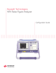
Figure 4-1
Test Set-up for Calibration and Measurement
Figure 4-2
Test Set-up for LO Accuracy and Troubleshooting
28
Chapter 4
Performance Tests
Section 4.07 LO Frequency Accuracy
Section 4.07 LO Frequency Accuracy
Specification 44.5 GHz ±50 MHz
i. Description
This test measures the Local Oscillator frequency by observing the output
frequency at the RF OUTPUT when a highly stable and accurate
26500 MHz is input.
ii. Equipment
Frequency Synthesizer
83640A
Spectrum Analyzer
E4407B
iii. LO Frequency Measurement Procedure
1. Set the 83640A combination for a CW signal of 26500 MHz at
-30dBm
2. Connect the equipment as shown in Figure 4-1. Connect the RF
output of the 83640A to the N8975A option K40 RF INPUT and
connect the E4407B input to the N8975A option K40 RF OUTPUT.
3. From E4407B, press [PRESET] on the Spectrum Analyzer then press
[CENTER FREQ] [1] [8] [GHz], [FREQ SPAN] [1] [0] [0] [MHz]. An 18
GHz signal at about -30 dBm should be observed near the center of
the display.
4. Press Spectrum Analyzer [Marker NORMAL] and [PEAK SEARCH].
Read the frequency in the upper right hand corner of the display.
The indicated frequency should be 18000 MHz ±50. Record the
frequency to the Test Record Card.
Chapter 4
29
Performance Tests
Section 4.07 LO Frequency Accuracy
Table 4-1
Performance Test Record
Test
Resul ts
4-4 Noise Figure Vs. Frequency
Gain
Actual NF
Max NF
Frequency (GHz)
(dB)
(dB)
(dB)
IF
RF
18.00
26.50
20.00
17.50
27.00
20.00
16.50
28.00
20.00
15.50
29.00
20.00
14.50
30.00
20.00
13.50
31.00
20.00
12.50
32.00
20.00
11.50
33.00
20.00
10.50
34.00
20.00
9.50
35.00
20.00
8.50
36.00
20.00
7.50
37.00
20.00
6.50
38.00
20.00
5.50
39.00
20.00
4.50
40.00
20.00
4-5 LO Frequency Accuracy
30
Min (MHz)
17950
Actual
Max (MHz)
18050
Chapter 4
Keysight N8975A Option K40
Blockdown Converter
Operating and Service Manual Special Supplement
5
Adjustments
The N8975A Option K40 has no internal adjustments.
31
Adjustments
32
Chapter 5
Keysight N8975A Option K40
Blockdown Converter
Operating and Service Manual Special Supplement
6
Service
Section 6.01 Introduction
This section contains information for troubleshooting and repairing the Down
Converter. Included are block diagrams, schematic diagrams, principles of
operation, and procedures for troubleshooting, repair, disassembly, and
re-assembly.
Section 6.02 Service Sheets
The pages following the service introduction are the service sheets comprising
of block diagrams, schematics, supplemental diagrams, theory, and
troubleshooting information.
Section 6.03 Safety Considerations
The pages following the service introduction are the service sheets comprising
of block diagrams, schematics, supplemental diagrams, theory, and
troubleshooting information.
a. Before Applying Power
Verify that the instrument is set to match the available line voltage and
that the correct fuse is installed. An uninterrupted safety earth ground
must be provided from the main power source to the instrument input
wiring terminals, power cable, or supplied power cable set.
i. Warnings and Cautions
33
Service
Section 6.04 Servicing the Instrument
Pay attention to WARNINGS and CAUTIONS. They must be followed
for your protection and to avoid damage to the equipment.
Maintenance described herein is performed with power supplied to the
instrument and with protective covers removed. Such maintenance should
be performed only by service-trained personnel who are aware of the
hazards involved (for example, fire and electrical shock). Where
maintenance can be performed without power supplied, the power should
be removed.
Any interruption of the protective (grounding) conductor (inside of outside
the instrument) or disconnecting the protective earth terminal will cause a
potential shock hazard that could result in personal injury. (Grounding one
conductor of a two conductor outlet is not sufficient protection). In
addition, verify that a common ground exists between the unit under test
and this instrument prior to energizing either unit.
Whenever it is likely that the protection has been impaired, the instrument
must be made inoperative and be secured against any unintended
operation.
If this instrument is to be powered via an auto-transformer (for voltage
reduction) make sure that the common terminal is connected to neutral
(that is, the grounded side of the mains supply).
Servicing instructions are for use by service trained personnel only. To
avoid dangerous electric shock, do not perform any servicing unless
qualified to do so.
Adjustments described in the manual are performed with power supplied
to the instrument while protective covers are removed. Energy available at
many points may, if contacted, result in personal injury.
Capacitors inside the instrument may still be charged even if the
instrument has been disconnected from its source of supply.
For continued protection against fire hazard, replace the line fuse(s) only
with 250V fuse(s) of the same current rating and type (F3.15AH, 250V). Do
not use repaired fuses or short circuited fuse holders.
Do not disconnect or remove any carriers or boards in the instrument unless the
instrument is unplugged. Some boards contain devices that can be damaged if
the board is removed when the power is on.
Section 6.04 Servicing the Instrument
Once an error has been detected, and the fault is known to be within the
instrument, it is necessary to place the instrument in a serviceable position.
refer to Top and Bottom Covers removal procedure near the end of this
section.
34
Chapter 6
Service
Section 6.05 Pozidrive Screwdrivers
Section 6.05 Pozidrive Screwdrivers
Many screws in the Down Converter appear to be Phillips type, but are not. To
avoid damage to the screw headshots, Pozidrive screwdrivers should be
used. 8710-0899 is the number 1 Pozidrive. 8710-0900 is number 2 Pozidrive.
Section 6.06 Hardware
The Down Converter has a mixture of unified national (inch) and metric
screws. The metric screws are defined in Industrial Fasteners Publication (IFI
500) and are identified in the list as metric. The unified national screws are
identified in the list as non-metric. To prevent thread damage, ensure that the
same type of screw and nut is used in each application.
Section 6.07 Assembly Locations
Assemblies in the Down Converter are numbered in groups, both by function
and by location. Refer to the service sheets for identification of assemblies.
Section 6.08 Parts and Cable Locations
The location of individual components mounted on the assemblies are shown
near the schematic diagram. The part reference designator is the assembly
designator plus the parts designator. For example, A2R9 is R9 on the A2
assembly. For specific component descriptions and ordering information,
refer to Table 8-1 on page 45, in Section 8-2.
Section 6.09 Test Point Locations
There are no test point locations identified.
Chapter 6
35
Service
Section 6.10 Cover Removal
Section 6.10 Cover Removal
Cover Removal
To remove the cover, remove the two screws that hold the rear bezel, as shown
in the above picture.
When replacing the cover re-tighten the captive screws in the rear bezel using
a 9 in-lbs T15 -screwdriver.
Section 6.11 Cleaning Intervals
Keysight Technologies recommends a 12 month interval between cleaning for
some parts of the Down Converter. Front panel connectors should be cleaned
every 6 months. Cleaning intervals, are dependent upon where the Down
Converter is used. It should be cleaned more frequently if the environment
used is a dusty or very humid area.
Section 6.12 Six Month Cleaning
Clean the cabinet of the instrument with a damp cloth only. Careful cleaning
of front panel connectors is essential to assure long, reliable connector life, to
prevent accidental damage to connectors, and to obtain maximum
measurement accuracy and repeatability.
Dirt and stubborn contaminants should be removed with a cotton swab or
lint-free cleaning cloth moistened with a solvent.
Use the least amount of solvent possible, and avoid wetting any plastic parts in
the connectors with the solvent.
Use liquid solvents rather then spray. If a spray must be used, always spray the
solvent onto a cloth or swab, never directly into a connector.
36
Chapter 6
Service
Section 6.13 Twelve Month Cleaning
Very dirty connectors can be cleaned with 91% isopropyl alcohol, Part Number
8500-0559.
Do not use aromatic or chlorinated hydrocarbons, esters, trepans, higher
alcohol's, keytones of ether-alcohols such as benzene toluene, turpentine, dioxin,
gasoline, cellosolve acetate, or carbon tetrachloride.
Whichever solvent is used, carefully avoid wetting the plastic support bead
inside the connector and blow the connector dry immediately with a gently
stream of compressed air. Support beads are easily damaged by solvents.
Interior surfaces, especially on precision 3.5 mm connectors, are very difficult
to reach, and it is easy to damage connectors in trying to clean them. One
suitable method is to cut off the sharp tip of a round wooden toothpick and
then to wrap it with a single layer of lint-free cleaning cloth. (A round wooden
toothpick or a very small diameter wooden rod is required: metal must never
be used because it will scratch the plated surface; diameter must not exceed
0.070 in. or 1.7mm. Moisten the cloth with a small amount of cleaning solvent
and carefully insert it into the connector to clean the interior surfaces. Use an
illuminated magnifying glass or microscope to see clearly the areas you wish to
clean. When you have cleaned a connector, always be sure that it is completely
dry before using it. Blow the connector dry with a gently stream of clean
compressed air and inspect it again under a magnifying glass to be sure that
no particles or solvent residues remain.
Section 6.13 Twelve Month Cleaning
Before cleaning, make sure the Down Converter is dis-connected from the power
source. This is to eliminate the possibility of electrical shock.
1. Remove the top and bottom covers to gain access to the interior of the
instrument.
2. Using a brush, remove dirt from the fan guard and fan blades.
3. Using compressed air, remove dust and dirt from the area behind the fan.
Blow air out through the fan and remove loose dirt.
4. Using air and/or a soft bristle brush, clean all other accessible areas of the
instrument, starting from the top, including the A1, A2 and A3 assemblies.
5. Replace the instrument covers.
Section 6.14 Overall Troubleshooting
The Overall Troubleshooting section consists of Principles of Operation and
Troubleshooting information for the Down Converter.
Chapter 6
37
Service
Section 6.15 Principles of Operation
Section 6.15 Principles of Operation
Input frequencies from 26.5 to 40 GHz are coupled into the A2 Down Converter
by coax to waveguide transition. A2FL1 prevents frequencies above and below
the 26.5 GHz to 40 GHz band from entering the mixer A2U1. Frequencies
above 40 GHz, in the image band (49-62.5 GHz), could mix with the 44.5 GHz
LO and cause spurious outputs. Frequencies from 26.5 to 40 GHz will mix with
this LO and create an Intermediate Frequency of 18 to 4.5 GHz which is
amplified by A2AR1 and routed to the RF OUTPUT. Further IF filtering is
performed with the input YIG filter in the N8975A. Note that the N8975A
Option K40 uses a LO below the incoming RF so that increasing RF frequency
results in increasing IF frequencies e.g. 26.5 GHz input corresponds to 18 GHz
output.
Section 6.16 Troubleshooting
This information is in the form of suggestions to allow the technician
troubleshooting the Down Converter to isolate the problem area as rapidly as
possible.
The information contained in the Block and Schematic Diagrams, should be
used to isolate a malfunction.
Failures generally fall into two categories: catastrophic failures or performance
degradation. In both cases it is important to first verify that the failure is in the
Down Converter, and not the test equipment.
Section 6.17 Check List
Make a visual inspection of the Down Converter and the connectors of any test
instruments. Look for damage to the coax connectors and check that the
internal fan is operating.
If the failure is catastrophic, check the +15 volt power supply.
If the LO frequency is incorrect A2A1 is faulty, replace A2 assembly.
If the problem is high noise figure, or low conversion gain, (but the LO
frequency is correct), the problem is most likely a failed A2AR1 IF amplifier, or
A2U1 mixer, or the input isolator, replace A2 assembly.
The IF amp has a gain of about 25 dB, and a noise figure of about 6 dB. The
mixer has a conversion loss and noise figure of about 7 dB. If these
components are OK, check that the LO is driving the L port of the mixer with
about +12 dBm.
38
Chapter 6
Service
Section 6.17 Check List
After completing any repairs to the Up/Down Converter, the tests in Chapter 4,
“Performance Tests”, on page 25 should be performed to ensure that the
instrument is operating within the specified limits.
The complete A2 assembly should be returned to Keysight Technologies, if faulty.
It will be repaired and re-aligned before returning to the customer.
Figure 6-1
Chapter 6
Blockdown Converter
39
Service
Section 6.17 Check List
Figure 6-2
Internal Assemblies Layout
Figure 6-3
Layout of A2 Block Down Converter
40
Chapter 6
Service
Section 6.17 Check List
Figure 6-4
Chapter 6
Troubleshooting Flow Diagram
41
Service
Section 6.17 Check List
42
Chapter 6
Keysight N8975A Option K40
Blockdown Converter
Operating and Service Manual Special Supplement
7
Operating the Down Converter with the 8970B/8971C
NF System
To operate the Down Converter with the 8970S/V Noise Figure Measurement
System set-up the 8970S/V as indicated in Section 3-13 of the 8970B
Operating and Service Manual. Connect the N8975A option K40 as shown in
Figure 7-1.
Load the ENR data to cover the frequency range to be measured.
i. Calibration and Measurement Procedure
As an example, the following procedure would be used to calibrate and
measure the noise figure and gain of a amplifier from 26.5 to 40 GHz every
500 MHz.
1. Set up the measurement parameters with the following key strokes;
a. Press [0] [.] [9] [SPECIAL FUNCTION]. Press [0] [.] [9] [SPECIAL
FUNCTION] (This initializes the special functions)
b. Press [1] [.] [7] [SPECIAL FUNCTION] (Sets up fixed LO variable IF
operation).
c. Press [4] [1] [.] [n] [SPECIAL FUNCTION] (Where n selects the correct
system local oscillator program).
If a 8673x Synthesizer is used, Press [4] [1] [.] [3] [SPECIAL
FUNCTION].
d. Press [2] [.] [1] [SPECIAL FUNCTION] (Sets up lower sideband
operation).
e. Press [START FREQ] [2] [6] [5] [0] [0] [ENTER] (Start frequency 26.5
GHz). (Ignore error E28, since the system is not yet calibrated).
f. Press [STOP FREQ] [4] [0] [0] [0] [0] [ENTER] (Stop frequency
40 GHz).
g. Press [STEP SIZE] [5] [0] [0] [ENTER] (Frequency step 500 MHz).
h. Press [3] [.] [1] [SPECIAL FUNCTION] [4] [4] [5] [0] [0] [ENTER]
(N8975A option K40 internal LO is 44.5 GHz).
43
Operating the Down Converter with the 8970B/8971C NF System
2. Calibrate the system by attaching the Noise Source to the N8975A option
K40 RF INPUT. When the Calibrate indicator goes out, and all bus activity
has ceased, the system is calibrated.
3. Connect the device under test between the Noise Source and the N8975A
Option K40 RF INPUT. Press [CORRECTED NOISE FIGURE AND GAIN]. The
8970B will display the measurement frequency, the gain and the noise
figure of the amplifier at each selected frequency.
For the Noise Figure Measurement System specifications to be valid, the
measurement must use the same START FREQ, STOP FREQ and STEP SIZE that
was used for calibration. None of the calibrated points can be skipped. Also, the
measurement must be done in the same direction as the calibration, for example,
from start frequency to stop frequency.
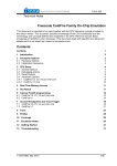
Figure 7-1
44
Test Setup for Calibration and Measurement with 8970B/71C
Chapter 7
Keysight N8975A Option K40
Blockdown Converter
Operating and Service Manual Special Supplement
8
Service Replaceable Parts
Section 8.01 Introduction
This section contains information for ordering parts. Table 8-1 lists all in
reference designator order.
Section 8.02 Accessories
Table 8-1
ITEM
PART NUMBER
QTY
DESCRIPTION
SUPPLIER
1
E4418-61025
1
CHASSIS
Keysight Technologies
2
N8975-40001
1
BEZEL
Keysight Technologies
3
N8975-00001
1
BASE PLATE
Keysight Technologies
4
N8975-00002
1
DC FILTER PLATE
Keysight Technologies
5
N8975-00008
1
FRONT PANEL
Keysight Technologies
6
N8975-80001
1
REAR PANEL
Keysight Technologies
7
N8975-00003
2
FAN MOUNTING PLATE
Keysight Technologies
8
N8975-61005
1
FAN 12VDC
Keysight Technologies
9
0380-4210
4
PSU/FILTER STANDOFFS
Keysight Technologies
10
N8975-61006
1
PSU
Keysight Technologies
11
5062-6615
1
CONN CX 2.4 RF INPUT
Keysight Technologies
12
2950-0132
1
NUT for RF INPUT
Keysight Technologies
13
5062-1247
1
CONN 3.5 IF OUTPUT
Keysight Technologies
14
2950-0132
1
NUT for above
Keysight Technologies
15
2190-0068
2
WASHER for above connectors
Keysight Technologies
16
N8975-00016
1
EMI SCRN
Keysight Technologies
17
3101-2359
1
Panel push switch
Keysight Technologies
18
R281A-FG
1
ADAPTER
Keysight Technologies
45
Service Replaceable Parts
Section 8.02 Accessories
Table 8-1
ITEM
PART NUMBER
QTY
DESCRIPTION
SUPPLIER
19
08970-60104
1
PCA Filter Assembly
Keysight Technologies
20
0515-0886
10
SCREW M3x6mm PAN
Keysight Technologies
21
0535-0025
4
NUT M3
Keysight Technologies
22
0515-1111
4
SCREW M3x16mm PAN
Keysight Technologies
23
0515-1232
2
SCREWS M3.5x8mm
Keysight Technologies
24
0535-0007
2
N U TS M3.5
Keysight Technologies
25
1251-0670
2
CRIMPS CONT-CONN F
Keysight Technologies
26
1251-2993
1
CONN SHELL POST .156
Keysight Technologies
27
0535-0023
6
NUT M4
Keysight Technologies
28
2190-0640
7
LOCK WASHERS M4
Keysight Technologies
29
1400-1552
4
ADHESIVE CABLE TIES
Keysight Technologies
30
E4418-61027
1
COVER
Keysight Technologies
31
34401-45011
1
HANDLE
Keysight Technologies
32
E4418-20008
1
REAR FRAME
Keysight Technologies
33
34401-86011
1
RUBBER BUMPER (FRONT)
Keysight Technologies
34
34401-86012
1
RUBBER BUMPER (REAR)
Keysight Technologies
35
8150-0449
1
RED WIRE
Keysight Technologies
36
8150-0456
1
BLUE WIRE
Keysight Technologies
37
8150-0452
1
GREEN WIRE
Keysight Technologies
38
N8975-20001
1
SEMI-RIGID CABLE I/P
Keysight Technologies
39
N8975-20002
1
SEMI-RIGID CABLE O/P
Keysight Technologies
40
0360-0016
1
TERMINAL SOLDER
Keysight Technologies
41
8150-0005
AR
BLACK WIRE
Keysight Technologies
42
N8975-60001
1
Block Down Converter
Keysight Technologies
43
0515-0433
4
SCREW M4x8mm PAN
Keysight Technologies
Table 8-2
Accessories
ITEM
PART NUMBER
QTY
DESCRIPTION
SUPPLIER
44
5063-9240
1
RACK ADAPTER KIT
Keysight Technologies
45
1250-2188
1
ADAPTER-COAX STR F-2.4 mm
Keysight Technologies
46
08971-60127
1
RF CABLE
Keysight Technologies
46
Chapter 8
This information is subject to change
without notice.
© Keysight Technologies 2007-2015
Edition 1, July 2015
N8975-90002
www.keysight.com