1
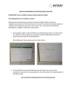
No.: 09 TS-10
April 4, 2009
TO:
Service Locations
FROM:
Technical Service
SUBJECT:
EPA07 MBE 900 Smart Remote Actuator Fault Codes:
SPN 615/FMI 7 - Smart Remote Actuator 2, Failsafe Mode, Motor On
SPN 615/FMI 9 - Smart Remote Actuator 2, Failsafe Mode, Motor Off
SPN 615/FMI 14 - Smart Remote Actuator 2, No Failsafe Mode,
Motor Off
ISSUE
Certain EPA07 MBE 900 engines are equipped with an electronic Smart Remote Actuator
(SRA2) for the exhaust flap instead of being pneumatically controlled. This system sometimes
experiences operational problems resulting in AWL/CEL and fault codes:
• SPN 615/FMI 7: Smart Remote Actuator 2, Failsafe Mode, Motor On.
• SPN 615/FMI 9: Smart Remote Actuator 2, Failsafe Mode, Motor Off.
• SPN 615/FMI 14: Smart Remote Actuator 2; No Failsafe Mode; Motor Off.
This letter is a revision of 07 TS-57Rev2 and supersedes all previous versions. The following
provides inspection and repair information for the Smart Remote Actuator, linkage and exhaust
flap. Refer to the EPA07 MBE 900 Troubleshooting Guide (DDC-SVC-MAN-0015) for proper
diagnosis of any fault and the EPA07 MBE 900 Workshop Manual (DDC-SVC-MAN-0034) for
component repair information.
CAUSE
There are two distinct causes for these fault codes:
1. SPN 615/FMI 7 - Smart Remote Actuator 2, Failsafe Mode, Motor On and SPN 615/FMI
14 - Smart Remote Actuator 2; No Failsafe Mode; Motor Off:
These fault codes may be caused by a flap that is stuck closed or has too long of a
response time to open the exhaust flap. Once the SRA is deactivated, it commands the
exhaust flap to open. If no movement or a slow response is detected, AWL/CEL and
fault codes become active (sometimes both codes are active at the same time).
2. SPN 615/FMI 9 - Smart Remote Actuator 2, Failsafe Mode, Motor Off:
This fault code may be caused by a seized exhaust flap actuator rod (linkage).
Corrosion builds up inside the ball sockets on both ends of the rod, stopping the
assembly movement. Every time the key is turned on, the SRA performs a quick check
by commanding the exhaust flap to close and open. If no movement is detected,
AWL/CEL and fault code become active.
Detroit Diesel 13400 Outer Drive, West / Detroit, Michigan 48239-4001
09 TS-10
-2-
4/4/2009
REPAIR PROCEDURE
Refer to the appropriate section of the EPA07 MBE 900 Troubleshooting Guide (DDC-SVCMAN-0015) for specific diagnostic information. As part of the troubleshooting procedure, proper
inspection and adjustment of the SRA linkage and exhaust flap may be necessary; refer to the
following.
Inspection and Cleaning of Exhaust Flap Rod (Linkage):
NOTE: Inspection should be completed before any component is replaced.
1. Make sure vehicle ignition is OFF. Remove retaining clip and carefully remove the
linkage from the exhaust flap lever arm and the SRA. See Figure 1.
Figure 1 - Actuator Linkage
2. Inspect the area inside of rod ball sockets for corrosion built up. If inside walls of the ball
socket had indication of corrosion, replace rod (linkage) using list of materials provided
in Table 1.
3. Use Figure 2 as reference for evaluation of the ball socket internal walls:
Figure 2 – Ball Socket – Corrosion on the Internal Walls
09 TS-10
-3-
4/4/2009
Inspection and Cleaning of Exhaust Flap Housing Assembly:
NOTE: Inspection should be completed before any component is replaced.
1. With the exhaust flap rod removed, rotate the flap from stop to stop to check for
unrestricted movement.
Closed Position
Open Position
Figure 3 – Exhaust Flap Lever Positions
a. If flap opens and closes smoothly, remove the exhaust pipe attached to the end
of the housing and clean any soot build-up from the internal walls and flap. See
Figure 4.
Figure 4 – Exhaust Flap Housing – Internal Walls Must be Clean of Soot
Deposit
b. If flap does not open and close smoothly, replace exhaust housing assembly
using part number provided in Table 2. Installation procedure is provided in the
EPA07 MBE 900 Service Manual (DDC-SVC-MAN-0034) in the “Installation of
Electronic Wastegate Exhaust Brake Assembly” section.
09 TS-10
-4-
4/4/2009
Procedure to Adjust and/or Replace the Exhaust Flap Rod (Linkage) Assembly:
1. Make sure vehicle ignition is OFF. Remove retaining clip and carefully remove the
linkage from the exhaust flap lever arm and the SRA. See Figure 5.
Figure 5 - Actuator Linkage
2. Using an emery cloth, carefully clean any rust from the ball studs on the exhaust flap
lever arm and on the SRA lever.
3. Rotate flap to full open position, the lever “A” should point downward. See Figure 6.
Figure 6 – Exhaust Flap Lever Adjustment
4. Apply the anti-seize lubricant inside of both ball sockets of the new linkage and on the
ball studs on the exhaust flap lever arm and SRA lever.
5. Install the linkage to the exhaust flap lever arm.
09 TS-10
-5-
4/4/2009
6. At the SRA, loosen the adjustment nut adjust ball socket to fit on the SRA actuator lever
as shown in Figure 7. The SRA lever should be in the full open (neutral) position when
this adjustment is performed.
Figure 7 – Smart Remote Actuator Lever Adjustment
7. Remove rod from SRA ball joint.
8. Adjust the ball joint socket on the actuator end of the linkage rod by extending it three
complete turns as shown in Figure 8.
Figure 8 – Smart Remote Actuator Lever Adjustment
09 TS-10
-6-
4/4/2009
8. Reinstall the ball joint socket onto the SRA lever and align the flats of the ball joint
sockets with the actuator and exhaust flap lever arms. See Figure 9.
Figure 9 – Smart Remote Actuator Lever Adjustment
9. Tighten the locknut against the ball joint socket to 12.5 N⋅m (9 lb⋅ft), being careful not to
damage (bend) the linkage or the SRA lever. See Figure 10.
NOTE: Verify flats on ball joint socket are parallel with the exhaust flap lever.
Ball Joint Sockets
Figure 10 – Parallel Ball Joint Sockets
09 TS-10
-7-
4/4/2009
10. Check for adequate clearance between the linkage rod and the bracket. See Figure 11.
Figure 11 – Clearance Check between Linkage Rod and Bracket
11. Turn vehicle ignition ON, connect DDDL/DDRS and clear all fault codes.
12. Turn vehicle ignition OFF and wait one minute.
13. Turn vehicle ignition ON, wait for the dashboard gauges to sweep, and start the engine.
Confirm proper operation.
REQUIRED MATERIAL
Refer to Table 1 for replacement part information.
Description
Part Number
Repair Procedure
Exhaust Flap Rod (linkage) Assy
A9261400246
Described in this letter
Exhaust Flap Housing
A9261401554
EPA07 MBE 900
Service Manual
Anti- Seize Lubricant
See anti-seize lubricant table
Table 2
---
Table 1 Service Repair Parts
09 TS-10
-8-
4/4/2009
Anti-Seize Lubricant is required on the ball joints. The following table lists all available antiseize lubricants from supplier Permatex® with package size and stock numbers:
Stock #
Description
09175
5g pouch, display boxed
81343
1 oz. tube, carded
80071
4 oz. brush-top bottle
80078
8 oz. brush-top bottle
Table 2 Permatex Anti-Seize Lubricants
CONTACT INFORMATION
Please contact the Detroit Diesel Customer Support Center at 313-592-5800 or email
[email protected] if you have any questions.