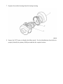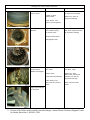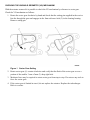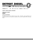
1
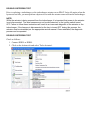
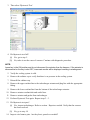
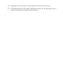
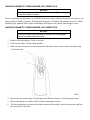
NUMBER: 8–10–13
S.M. REF.: Listed in Table
ENGINE: EPA07 Series 60
DATE: August 2013
SUBJECT: DOUBLE HYSTERESIS TEST
ADDITIONS, REVISIONS, OR UPDATES
Publication Number
Platform
DDC-SVC-MAN-0009
EPA07 Series 60
DDC-SVC-MAN-0005
Section Title
Change
Double Hysteresis Test
Link changed in step 13a.
Variable Geometry
Turbocharger (VGT) Inspection
This is a new section.
Checking the Variable
Geometry (VG) Mechanism
Link changed in step 4.
NOTE: Page numbers are based on the most recent version of the individual publication and may be adjusted throughout the annual print cycle.
THIS SECTION APPLIES TO DDC-SVC-MAN-0009
DOUBLE HYSTERESIS TEST
Prior to replacing a turbocharger or the turbocharger actuator on an EPA07 Series 60 engine when the
hysteresis test fails, you must perform a hysteresis test with the actuator removed from the turbocharger.
NOTE:
While the actuator is being removed from the turbocharger, it is important that power to the actuator
is not disconnected. The wire harness must not be disconnected, or the ignition switch turned
OFF. Failure to follow these instructions will result in an inaccurate diagnosis of the actuator or the
turbocharger. If the harness is disconnected or the key is turned OFF during this process, the
actuator must be reinstalled per the appropriate service manual. Once reinstalled, the diagnostic
process can be repeated.
DOUBLE HYSTERESIS TEST
Check as follows:
1. Connect DDDL or DDRS.
2. Click on the Actions tab and select 'Turbo Actuator'.
3. Then select 'Hysteresis Test'.
4. Did hysteresis test fail?
[a]
Yes; go to step 5.
[b]
No; turbo is not the cause of concern. Continue with diagnostic procedure.
NOTE:
Leave key in the ON position and do not disconnect the actuator from the harness. If the actuator is
disconnected or the key is shut OFF, inaccurate results will be displayed resulting in misdiagnosis.
5. Verify the cooling system is cold.
6. Remove the radiator cap to verify that there is no pressure in the cooling system.
7. Reinstall the radiator cap.
8. Remove the upper coolant line to the turbocharger actuator and plug line with the appropriate
fitting.
9. Remove the lower coolant line from the bottom of the turbocharger actuator.
10. Remove actuator coolant inlet and outlet lines.
11. Remove actuator and gasket from turbocharger.
12. Perform Hysteresis Test again. Repeat steps 2 - 3.
13. Did hysteresis test pass?
[a]
Yes; inspect turbocharger. Refer to section . Repair as needed. Verify that the concern
has been resolved.
[b]
No; go to step 14.
14. Inspect wire harness pins. Are they bent, spread or corroded?
[a]
If damaged, repair the harness. Verify that the concern has been resolved
[b]
If the harness pins are OK, replace turbocharger actuator per the appropriate service
manual. Verify that the concern has been resolved.
VARIABLE GEOMETRY TURBOCHARGER (VGT) INSPECTION
NOTICE:
The only time you need to refer to this section is if the sector gear
is stuck or limited in travel.
Prior to replacing a turbocharger on an EPA07 Series 60 engine when the hysteresis test passes, you
must perform Variable Geometry Turbocharger inspection to identify the primary reason for failure.
Identifying the primary failure of the turbocharger will improve any future turbochargers issues.
VARIABLE GEOMETRY TURBOCHARGER (VGT) INSPECTION
NOTICE:
Once the turbine housing clamp is removed the turbocharger
cannot be reassembled and used.
1. Remove the turbocharger. Refer to section .
2. Lubricate the turbo V-band clamp threads.
3. Slide a deep well socket over the clamp and strike the socket to remove the anti-tamper clip
(1) from the nut.
4. Remove the nut on the turbo V-band clamp and slide the clamp over the bearing housing.
5. Place turbocharger on a table with the turbine housing face down.
6. Tilt the turbocharger and strike the turbine housing with a mallet, rotate and continue until the
two halves have loosened.
7. Separate the turbine housing from the bearing housing.
8. Inspect the VGT vanes to identify the failure mode. Use the identification chart below to
properly identify the primary failed part and take the required actions.
Identifying the Correct Primary Failed Part:
Failure Mode
Carbon Build up on
the VG Vanes
Possible Causes
Required Action
Poor combustion:
Find the source of the
excessive soot and repair.
Plugged Air Filter,
Turbo Actuator,
Replace the Turbo as
progressive damage.
Engine Sensor, Fuel
Injector, Low Compression
Rust and White
Residue
Progressive damage
from Coolant entering
the Exhaust track:
Find the source of the coolant
and repair. Replace the turbo
as progressive damage.
Cracked Cylinder Head
Leaking EGR Cooler
Vanes are Bent,
Turbine Wheel
Blades are Damaged
Progressive Damage
from debris:
Find the source of
the debris, repair.
Dropped Valve
Replace the turbo,
EGR Cooler and exhaust
manifold inner tube as
progressive damage.
Broken EGR Valve Butterfly
Debris Stored in the
EGR Cooler from another
Failure
Refer to Service Letter
13TS1
Light Impact Damage
on the Vanes
9. If none of the failure modes match your turbocharger, contact Detroit Customer Support Center
for further directions 1-800-445-1980.
THIS SECTION APPLIES TO DDC-SVC-MAN-0005
CHECKING THE VARIABLE GEOMETRY (VG) MECHANISM
With the actuator removed it is possible to check the VG mechanism by reference to sector gear.
Check the VG mechanism as follows:
1. Rotate the sector gear clockwise by hand and check that the setting pin supplied in the service
kits fits through the gear and engages in the 5mm reference hole (2) in the bearing housing.
Remove setting pin.
Figure 1
Sector Gear Setting
2. Rotate sector gear (1) counter-clockwise and verify that the flank of the sector gear covers a
portion of the smaller 3 mm x 2mm (3) deep sight hole.
3. Moderate force may be required to rotate sector gear from stop to stop. Do not use any tools to
force the sector gear.
4. If the sector gear is limited in travel, do not replace the actuator. Replace the turbocharger.
Refer to section .
ADDITIONAL SERVICE INFORMATION
Additional service information is available in Power Service Literature.
Detroit TM , DDC®, Series 60® and the spinning arrows design are registered trademarks of Detroit Diesel Corporation.
© Copyright 2013 Detroit Diesel Corporation. All rights reserved. Printed in U.S.A.