1
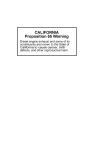
NUMBER: 4–10–13
S.M. REF.: Listed in Table
ENGINE: EPA07 Series 60
DATE: April 2013
SUBJECT: CHECKING THE VARIABLE GEOMETRY (VG) MECHANISM / DOUBLE HYSTERESIS
TEST
ADDITIONS, REVISIONS, OR UPDATES
Publication Number
Platform
Section Title
Change
DDC-SVC-MAN-0005
EPA07 Series 60
Checking the Variable
Geometry (VG) Mechanism
Most of the procedure is new.
DDC-SVC-MAN-0009
EPA07 Series 60
Double Hysteresis Test
Several steps were added to
the procedure.
NOTE: Page numbers are based on the most recent version of the individual publication and may be adjusted throughout the annual print cycle.
THE FOLLOWING APPLIES TO DDC-SVC-MAN-0005
TURBOCHARGER ELECTRIC ACTUATOR
The actuator is connected to the engine harness of the Motor Control Module (MCM) with a connector.
The actuator is activated electrically in key-on position prior to engine start. A span check can be
commanded through the MCM. Successful actuation can be heard as the Variable Geometry (VG)
mechanism contacts the open and closed stop settings. The MCM accumulates useful data during
operation. Before taking corrective action refer the Series 60 DDEC VI Troubleshooting Manual,
(DDC-SVC-MAN-0009).
The performance specification of the actuator is determined by application specific software which is
loaded during manufacture. The DDDL 7.X system pre-aligns the actuator to the turbocharger prior to
actuator installation; and calibrates the actuator and turbocharger after installation.
The actuator is water cooled. The lower port will be used for coolant inlet and the upper port for coolant
return.
REMOVAL OF ACTUATOR
Remove the actuator as follows:
NOTE:
When possible the actuator should be removed from the turbocharger with the turbocharger installed
on the engine.
NOTICE:
Ensure the actuator is not operational (key-OFF) and completely
connected during cleaning process.
1. Actuator should not be operational (key-OFF) position.
2. Ensure electrical harness is connected and coolant connections are installed.
PERSONAL INJURY
To avoid injury while performing the test or procedure, wear
adequate eye, face protection, and heat-resistant gloves.
3. With actuator installed on turbocharger, clean with water pressure or steam cleaning equipment.
4. Disconnect the actuator harness from the engine harness.
5. Verify the coolant system is cold.
6. Remove the radiator cap to verify that there is no pressure in the coolant system.
7. Drain the cooling system. Refer to section .
8. Remove the upper coolant line to the turbocharger actuator
9. Remove the lower coolant line from the bottom of the turbocharger actuator.
10. Remove actuator coolant inlet and outlet lines.
11. Remove actuator and gasket from turbocharger.
CLEANING OF THE ACTUATOR
Clean the actuator assembly as follows:
1. Hold the actuator and with the output shaft facing towards the ground to ensure that the debris
is flushed out of the actuator assembly.
NOTICE:
Ensure the actuator drive pinion and cavity is free from debris.
Tooth wear and mechanical failure may occur if the drive pinion
and cavity are not kept clean.
EYE INJURY
To avoid injury from flying debris when using compressed air,
wear adequate eye protection (face shield or safety goggles)
and do not exceed 276 kPa (40 psi) air pressure.
NOTICE:
Ensure debris is not deposited in the space between the drive
pinion and casting.
2. Spray the solvent cleaner and compressed air onto the actuator drive gear and cavity.
3. Clean the actuator assembly using a shop rag or soft brush.
INSPECTION OF THE ACTUATOR
Inspect the actuator as follows:
NOTICE:
A damaged actuator cannot be repaired. A repaired actuator
would probably fail key-on calibration checks and may cause
engine damage to the engine. Replace a damaged actuator with a
new actuator.
1. Visually check for electrical continuity.
2. Visually check actuator harness connector pins ensure the pins are not damaged.
3. Inspect wires at the actuator and connector for damage.
4. Visually inspect drive pinion for worn, missing or damaged teeth.
CHECKING THE VARIABLE GEOMETRY (VG) MECHANISM
With the actuator removed it is possible to check the VG mechanism by reference to sector gear.
Check the VG mechanism as follows:
1. Rotate the sector gear clockwise by hand and check that the setting pin supplied in the service
kits fits through the gear and engages in the 5mm reference hole (2) in the bearing housing.
Remove setting pin.
Figure 1
Sector Gear Setting
2. Rotate sector gear (1) counter-clockwise and verify that the flank of the sector gear covers a
portion of the smaller 3 mm x 2mm (3) deep sight hole.
3. Moderate force may be required to rotate sector gear from stop to stop. Do not use any tools to
force the sector gear.
4. If the sector gear is limited in travel, do not replace the actuator. Replace the turbocharger.
INSTALLATION OF THE ACTUATOR
Install the actuator as follows:
NOTICE:
Ensure refer to section is completed before proceeding.
1. Connect DDDL or DDRS to the 9-pin connector.
2. Connect the actuator to the engine harness.
3. Perform the pre-installation service routine.
NOTE:
When the pre-installation service routine has been completed ensure the actuator is operational
(key-ON) but the engine is not started.
NOTE:
The alignment pin will fit through the sector shaft and into the turbocharger housing; once aligned, do
not move the sector shaft.
NOTICE:
Only apply grease supplied with actuator to the actuator sector
gear teeth.
4. When the pre-installation service routine has been completed, ensure the actuator is operational
(key ON, engine OFF).
5. Apply the supplied grease from the bolt kit to the teeth of the sector shaft.
6. Remove the alignment pin from the sector shaft.
7. Using new bolts and a gasket from the bolt kit, install the actuator onto the turbocharger housing.
NOTE:
Ensure that the speed sensor wire clips are on the correct mounting bolts (front bolts) before
installing the mounting bolts.
8. Torque the four actuator mounting cap screws to 3 N·m (26 lb·in.) using a diagonal sequence.
9. Ensure actuator harness and engine harness are routed correctly.
10. Final torque the actuator mounting cap screws to 11 N·m ( 97 lb·in.) using a diagonal sequence.
11. Using DDDL, perform Self-Calibration Routine under Actions, Turbo Actuator.
NOTE:
If the Self-Calibration routine fails, remove actuator and repeat installation one additional time. If
the Self-Calibration Routine fails again, replace the turbocharger.
12. Using DDDL, perform a Turbo Hysteresis Test.
[a]
If the Hysteresis test fails, perform section 2.1 Double Hysteresis Test in the
Troubleshooting manual.
[b]
If the Hysteresis Test passes, continue with the installation procedure of the Turbo Actuator.
13. Turn ignition OFF.
NOTE:
When tightening coolant line, support line to prevent contact with actuator.
14. Attach coolant pipes and torque the fittings to 34 N·m (25 lb·ft).
15. Fill the coolant system, Refer to section .
16. Turn the ignition ON (key ON, engine OFF). Perform the scan test using DDDL.
17. Connect DDDL/DDRS and clear fault codes.
18. Start and run the engine for verification of proper engine operation.
ENGINE EXHAUST
To avoid injury from inhaling engine exhaust, always operate
the engine in a well-ventilated area. Engine exhaust is toxic.
PERSONAL INJURY
To avoid injury before starting and running the engine, ensure
the vehicle is parked on a level surface, parking brake is set,
and the wheels are blocked.
THE FOLLOWING APPLIES TO DDC-SVC-MAN-0009
DOUBLE HYSTERESIS TEST
Prior to replacing a turbocharger or the turbocharger actuator on an EPA07 Series 60 engine when the
hysteresis test fails, you must perform a hysteresis test with the actuator removed from the turbocharger.
NOTE:
While the actuator is being removed from the turbocharger, it is important that power to the actuator
is not disconnected. The wire harness must not be disconnected, or the ignition switch turned
OFF. Failure to follow these instructions will result in an inaccurate diagnosis of the actuator or the
turbocharger. If the harness is disconnected or the key is turned OFF during this process, the
actuator must be reinstalled per the appropriate service manual. Once reinstalled, the diagnostic
process can be repeated.
DOUBLE HYSTERESIS TEST
Check as follows:
1. Connect DDDL or DDRS.
2. Click on the Actions tab and select ’Turbo Actuator’.
3. Then select ’Hysteresis Test’.
4. Did hysteresis test fail?
[a]
Yes; go to step 5.
[b]
No; turbo is not the cause of concern. Continue with diagnostic procedure.
NOTE:
Leave key in the ON position and do not disconnect the actuator from the harness. If the actuator is
disconnected or the key is shut OFF, inaccurate results will be displayed resulting in misdiagnosis.
5. Verify the cooling system is cold.
6. 6. Remove the radiator cap to verify that there is no pressure in the cooling system.
7. Reinstall the radiator cap.
8. Remove the upper coolant line to the turbocharger actuator and plug line with the appropriate
fitting.
9. Remove the lower coolant line from the bottom of the turbocharger actuator.
10. Remove actuator coolant inlet and outlet lines.
11. Remove actuator and gasket from turbocharger.
12. Perform Hysteresis Test again. Repeat steps 2 - 3.
13. Did hysteresis test pass?
[a]
Yes; inspect turbocharger. Refer to section . Repair as needed. Verify that the concern
has been resolved.
[b]
No; go to step 14.
14. Inspect wire harness pins. Are they bent, spread or corroded?
[a]
If damaged, repair the harness. Verify that the concern has been resolved
[b]
If the harness pins are OK, replace turbocharger actuator per the appropriate service
manual. Verify that the concern has been resolved.
ADDITIONAL SERVICE INFORMATION
Additional service information is available in Power Service Literature.
Detroit TM , DDC®, Series 60® and the spinning arrows design are registered trademarks of Detroit Diesel Corporation.
© Copyright 2013 Detroit Diesel Corporation. All rights reserved. Printed in U.S.A.