1
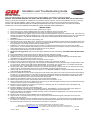
Installation and Troubleshooting Guide
All rights reserved. Reproduction or use of content, in any manner, without express written permission by CDI Electronics, Inc., is prohibited.
TROUBLESHOOTING
NOTICE: The trigger cannot be bench tested except with the CDI Electronics Trigger Tester P/N: 511-9710 (the tester can
also be used to test the trigger while on the engine). Be sure to follow the instructions at the bottom when lining up the
rotor and disk.
Dead or no spark until you let off of the key switch:
1. Clean ALL engine ground wires from the battery thru the engine cowling, splash pan, top cowl and support brackets.
2. Verify that there is at least 9-1/2 volts on the White wire going to the switch box (from the engine harness) while
cranking the engine.
3. Verify that there is at least 9 volts on the Brown wire going to the trigger while cranking the engine. If the voltage is
low and the voltage on the White wire from the harness is above 9-1/2 volts, disconnect the wires from the switchbox,
then check the resistance from the White terminal beside the Red terminal (from the White/Red wire on the CDI
Electronics switchbox) to the Brown terminal going to the trigger. You should read 60-76 ohms. A high reading
indicates a possible bad switchbox.
4. Check resistance between the White wire and engine ground. It should read less than 1 ohm. If it reads higher, make
sure the Black ground wire is connected to engine ground.
5. Connect a secondary ground wire (12 gauge) from the negative battery cable to the base (or case) of the switch box.
6. Using the 511-9710 Trigger Tester, check the output of the trigger according to the directions for the tester.
Only has spark as long as the starter is engaged: Usually indicates a bad trigger. Test per above.
Fires all cylinders but engine will not run:
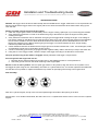
1. Recheck sensor wheel to make sure it is right side up. See diagrams below for correct placement.
2. Check the ground wire from the starter mounting to the support plate.
Misses on one or more cylinders: Connect spark gap checker to all cylinders, align the rotor to each cylinder in turn,
and trigger the pack using the 511-9701 Battery CD Tester. If a cylinder fails to fire, or if another cylinder fires besides the
one that the rotor is pointed to, replace the distributor cap. Watch for spark plug wires arcing to the engine block.
Disk assembly:
Note: On 6 cylinder engines, the tip of the rotor must split the right hand side of the opening in the disk.
Service Note: On a double notched shaft, the wide notch is for a 4 cylinder disk and the narrow notch is for the 6 cylinder
engines.
CDI Electronics • 353 James Record Road SW • Huntsville, AL 35824
Web Support: www.cdielectronics.com • Tech Support: 1-866-423-4832 • Order Parts: 1-800-467-3371
All rights reserved. Reproduction or use of content, in any manner, without express written permission by CDI Electronics, Inc., is prohibited.
Rev B • 1/08/13
Page - 3 of 3
QF-319