1
SERIES 60 SERVICE MANUAL
This page intentionally left blank.
All information subject to change without notice.
(Rev. 01/04)
6SE483 0303 Copyright © 2003 DETROIT DIESEL CORPORATION
From Bulletin 20-60-03Rev.
1-364c
1.19
CONNECTING ROD
1.19 CONNECTING ROD
Two types of connecting rod are used in Series 60 engines. The open end or saddle type connecting
rod is used with cast iron pistons which have bolt-on, style piston pins. The closed end or trunk
type connecting rod is used with forged steel pistons which have floating, trunk style piston pins.
NOTICE:
Do not mix forged steel pistons used with closed end connecting
rods and cast iron pistons used with open-end connecting rods
in the same engine. This will cause severe engine damage.
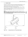
OPEN-END CONNECTING ROD: The open-end connecting rod is forged to an "I" section with
an open or saddle type contour at the upper end and a bearing cap at the lower end. The surface of
the connecting rod is shot-peened for added strength. Therefore, no grinding is permitted since
it will remove the benefits of shot-peening.
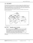
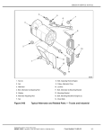
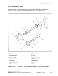
The upper end of the connecting rod is machined to match the contour of the piston pin. The
piston pin is secured to the connecting rod with two special bolts and spacers. The lower bearing
cap is secured to the connecting rod by two specially machined bolts and nuts. See Figure 1-299.
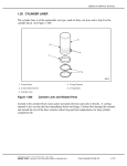
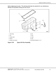
1. Connecting Rod Nut (2)
5. Piston Pin Bolt (2)
2. Notched Bolt (2)
6. Connecting Rod Bearing Cap
3. Connecting Rod
7. Bearing Shells
4. Spacer Washer (2)
Figure 1-299
Connecting Rod and Bearing Shells (Open-End Rod)
(Rev. 01/04)
1-364d
From Bulletin 20-60-03Rev.
All information subject to change without notice.
6SE483 0303 Copyright © 2003 DETROIT DIESEL CORPORATION
SERIES 60 SERVICE MANUAL
The two special bolts locate the cap relative to the upper end. The assembly is machined as a unit
and must not be used in the engine with any other cap or upper end. Orientation of the cap to the
upper end is identified by stamped numbers.
NOTE:
The Series 60G engine connecting rod is shorter in length and identified by "Natural
Gas" on the side.
The current connecting rods with smaller rod chamfers replaced the former connecting rods,
effective with the following engine serial numbers: (listed in Table 1-7.)
Table 1-7
Engine Model
Engine Serial Number
6067WK60 (11.1L)
6R184522
6067GK60 (12.7L)
6R188251
New Connecting Rod Replacements
This change was made to allow installation of new, wider connecting rod bearings that provide
improved oil film thickness and reduced bearing pressures.
The rod chamfers on the current connecting rods are smaller than those on the former rods. This
has been done to provide proper support for the wider bearings. To conform with this change,
new crankshafts with smaller fillet radii have been released. Refer to section 1.7 for information
on the new crankshafts.
NOTE:
The current connecting rods, bearings, and crankshafts must be used together to ensure
interchangeability. Former parts cannot be mixed with new parts in the same engine.
The former connecting rods will continue to be available for engines built prior to the
unit serial numbers as listed in Table 1-7.
The connecting rod bearing shells are precision made and are of the replaceable type. The upper
bearing shell is seated in the connecting rod and a lower bearing shell is seated in the connecting
rod cap. These bearings are not identical. The upper and lower bearing shells are located in the
connecting rod by a tang at the parting line at one end of each bearing shell. See Figure 1-299.
The tri-metal bearing wear surfaces use a steel backing. First, an optimum composition (copper,
tin and lead) lining is bonded to the steel back. A nickel barrier above the lining and the overlay
serves to prevent tin migration. A soft lead overlay, 0.025 mm (0.001 in.) thick, provides run-in
protection, and an initial wear surface. A flash tin plate, front and back, is for added corrosion
protection and resistance during shipping and handling. These bearings are identified by the satin
silver sheen of the tin when new, and a dull gray of the overlay after being in service.
All information subject to change without notice.
(Rev. 01/04)
6SE483 0303 Copyright © 2003 DETROIT DIESEL CORPORATION
From Bulletin 20-60-03Rev.
1-365
1.19
CONNECTING ROD
The oil hole through the upper bearing shell supplies oil to the oil passage in the connecting rod,
thereby providing a supply of lubricating oil from the crankshaft to the connecting rod bearings,
piston-pin bushing, and underside of the piston dome. The upper shell is grooved from one edge
to the oil hole. The lower shell has a full-length (180 degree) groove. See Figure 1-300.
Figure 1-300
Connecting Rod Bearing Detail (Open-End Rod)
The connecting rods bearing caps are numbered according to the cylinder position with matching
numbers stamped on the connecting rod tang side.
The current, wider connecting rod bearings replaced the former connecting rod bearings as
listed in Table 1-24.
This change was made to improve oil film thickness and reduce bearing pressures. The current
bearings are 47.44-47.14 mm (1.868-1.856 in.) wide. The former bearings were 43.44-43.13 mm
(1.710-1.698 in.) wide. To provide full support for the wider bearings, new connecting rods
with smaller rod chamfers and current crankshafts with smaller fillet radii were also released.
Refer to section 1.7 for information on the current crankshafts.
NOTE:
The current connecting rod bearings, connecting rods, and crankshafts must be used
together to ensure interchangeability. Former parts cannot be mixed with new parts in
the same engine. The former bearing shells will be available for engines built prior to the
unit serial numbers as listed in Table 1-7.
(Rev. 01/04)
1-366
From Bulletin 20-60-03Rev.
All information subject to change without notice.
6SE483 0303 Copyright © 2003 DETROIT DIESEL CORPORATION
SERIES 60 SERVICE MANUAL
CLOSED-END CONNECTING ROD: Each connecting rod is forged to an "I" section with a
closed hub at the upper end and a bearing cap at the lower end. See Figure 1-302. Unlike the
open-end connecting rod, the closed end rod is not drilled prior to model year 2000. Lubrication
for the piston and piston pin is supplied by a spray nozzle bolted to the block at the base of each
cylinder bore. (Current blocks are drilled and tapped for installation of the cooling nozzles into
the main oil gallery.) These nozzles spray crankcase oil upwards onto the piston and piston pin
during engine operation, providing the required lubrication and cooling.
NOTE:
The current connecting rod for 14 L engines and model year 2000 12.7 L engines
use a drilled passage way through the rod to lubricate the piston pin bushing. These
connecting rods can be mixed within an engine with the former non-drilled connecting
rod. See Figure 1-301.
Figure 1-301
Current and Former Closed-End Connecting Rods
All information subject to change without notice.
(Rev. 01/04)
6SE483 0303 Copyright © 2003 DETROIT DIESEL CORPORATION
From Bulletin 20-60-03Rev.
1-367
1.19
CONNECTING ROD
1. Connecting Rod Nut (2)
4. Connecting Rod Bearing Cap
2. Notched Bolt (2)
5. Bearing Shells
3. Connecting Rod
Figure 1-302
Connecting Rod and Bearing Shells (Closed-end Rod)
The upper end of the rod has a pressed-in, machined bushing with two scallops, 180 degrees apart.
Spray oil entering these scallops lubricates the piston pin and bushing during engine operation.
The piston pin floats in the bushings of both the piston and the connecting rod.
The lower bearing cap is secured to the connecting rod by two specially machined bolts and
nuts. See Figure 1-302.
The two special bolts locate the cap relative to the upper end. The assembly is machined as a unit
and must not be used in the engine with any other cap or upper end. Orientation of the cap to the
upper end is identified by stamped numbers.
(Rev. 01/04)
1-368
From Bulletin 20-60-03Rev.
All information subject to change without notice.
6SE483 0303 Copyright © 2003 DETROIT DIESEL CORPORATION
SERIES 60 SERVICE MANUAL
Closed-end connecting rods prior to model year 2000 have no center-drilled lubricating oil
passage. See Figure 1-303, see Figure 1-304 and see Figure 1-305.
Figure 1-303
Connecting Rod Bearing Detail (Closed End Rod Without a
Drilled Passage)
Figure 1-304
Connecting Rod Bearing Detail for Pleasure Craft Marine (Closed
End Rod Without a Drilled Passage)
All information subject to change without notice.
(Rev. 01/04)
6SE483 0303 Copyright © 2003 DETROIT DIESEL CORPORATION
From Bulletin 20-60-03Rev.
1-369
1.19
CONNECTING ROD
Figure 1-305
Connecting Rod Bearings for 14 L and 12.7 L Engines
The connecting rod bearing caps are numbered according to the cylinder position with matching
numbers stamped on the connecting rod tang side.
The connecting rod bearing shells are precision made and are of the replaceable type. The
upper bearing shell is seated in the connecting rod and a lower bearing shell is seated in the
connecting rod cap. The upper and lower bearings are identical (except for marine applications
see Figure 1-304). The upper and lower bearing shells are located in the connecting rod by a tang
at the parting line at one end of each bearing shell.
The tri-metal bearing wear surfaces use a steel backing. First, an optimum composition (copper,
tin and lead) lining is bonded to the steel back. A nickel barrier above the lining and the overlay
serves to prevent tin migration. A soft lead overlay, 0.025 mm (0.001 in) thick, provides run-in
protection, and an initial wear surface. A flash tin plate, front and back, is for added corrosion
protection and resistance during shipping and handling. These bearings are identified by the satin
silver sheen of the tin when new and a dull gray of the overlay after being in service.
(Rev. 01/04)
1-370
From Bulletin 20-60-03Rev.
All information subject to change without notice.
6SE483 0303 Copyright © 2003 DETROIT DIESEL CORPORATION
SERIES 60 SERVICE MANUAL
1.19.1
Repair or Replacement of Connecting Rod
To determine if repair is possible or replacement is necessary, perform the following procedure.
See Figure 1-306.
Figure 1-306
Flowchart for Repair or Replacement of Connecting Rod
All information subject to change without notice.
(Rev. 01/04)
6SE483 0303 Copyright © 2003 DETROIT DIESEL CORPORATION
From Bulletin 20-60-03Rev.
1-371
1.19
CONNECTING ROD
1.19.2
Removal and Cleaning of the Connecting Rod
Before removal, make sure the connecting rods and caps are stamped with their correct cylinder
location. If not marked, stamp location (1-6) on the tang side (cooler side) of the rod and cap.
Refer to section 1.18.2 for piston and connecting rod assembly removal procedure.
1.19.3
Disassembly of Connecting Rod
Disassemble the connecting rod as follows:
NOTE:
It is best to disassemble, inspect and assemble each connecting rod separately. It is
very important to keep the connecting rod cap, and the upper and lower bearing shells to
the original connecting rod.
1. Loosen and remove the two connecting rod nuts. See Figure 1-299.
2. Remove connecting rod cap and bearings shells. See Figure 1-299.
1.19.3.1
Inspection of Connecting Rod
Clean the bearings prior to inspection as follows:
1. Clean the bearings with fuel oil.
To avoid injury from flying debris when using compressed
air, wear adequate eye protection (face shield or safety
goggles) and do not exceed 40 psi (276 kPa) air pressure.
2. Dry the bearings with compressed air.
Inspect the open-end connecting rod as follows:
1. Inspect the connecting rod saddle at the piston pin contact surface for traces of fretting
and corrosion.
2. To repair, wet with fuel oil and smooth with crocus cloth.
(Rev. 01/04)
1-372
From Bulletin 20-60-03Rev.
All information subject to change without notice.
6SE483 0303 Copyright © 2003 DETROIT DIESEL CORPORATION
SERIES 60 SERVICE MANUAL
Inspect the closed-end connecting rod as follows:
NOTICE:
Reusing a connecting rod with a damaged or loose bushing may
result in severe cylinder kit damage.
1. Inspect the piston pin bushing for indications of scoring. If scoring is found, replace
the rod.
2. Inspect the piston pin bushing for indications of overheating. A bushing that has
overheated may become loose. If a loose bushing is found, the rod must be replaced.
1.19.4
Assembly of Connecting Rod
Assemble connecting rod as follows:
1. Install the connecting rod cap with the numbers on the same (oil cooler) side on the
connecting rod.
2. Lubricate the bolt threads with clean engine oil.
NOTICE:
Do not over torque the connecting rod bolt nuts. Over torque
may permanently distort the connecting rod cap.
NOTICE:
Be sure the connecting rod bolt has not turned in the connecting
rod before torque is applied to the nut.
3. Torque the bolt nuts to 160-185 N·m (118-137 lb·ft).
All information subject to change without notice.
(Rev. 01/04)
6SE483 0303 Copyright © 2003 DETROIT DIESEL CORPORATION
From Bulletin 20-60-03Rev.
1-373
1.19
CONNECTING ROD
1.19.4.1
Inspection of Assembled Connecting Rod
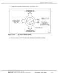
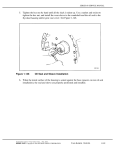
Measure the connecting rod bearing diameter at five locations. See Figure 1-307.
Figure 1-307
Dimensional Inspection of Connecting Rods
1. Calculate size of diameter at split line, W. [W= (A+B) ÷ 2]
2. Calculate the average bore out-of-round, X. [X=W-C] X must be between -0.012 and
0.012 mm (-0.0005 and 0.0005 in.).
3. Calculate the average connecting rod bearing bore size, Y. [Y= (W+X) ÷ 2] Y must be
between:
[a]
For 12.7 and 11.1 L; 91.288 and 91.313 mm (3.594 and 3.595 in.).
[b]
For 14L and 12.7 EGR On-Highway; 101.288 and 101.3133 mm (3.988 and 3.989
in.).
(Rev. 01/04)
1-374
From Bulletin 20-60-03Rev.
All information subject to change without notice.
6SE483 0303 Copyright © 2003 DETROIT DIESEL CORPORATION
SERIES 60 SERVICE MANUAL
4. Determine taper, Z. [Z=D2-D1] Z must be between -0.012 and 0.012 mm (-0.0005 and
0.0005 in.).
5. Determine the rod length by finding the distance between E1 and E2. See Figure 1-307.
[a]
The acceptable rod length specification for 11.1 Liter connecting is: 281.95-282.05
mm (11.1004-11.1043 in.).
[b]
The acceptable rod length specification for both 12.7 Liter and 14 Liter connecting
rods is: 269.25-269.35 mm (10.6004-10.6043 in.).
[c]
The acceptable rod length specification for Series 60G Engines is: 262.90-263.00
mm (10.3504-10.3543 in.).
[d]
If the connecting rod bore is not to specifications, the rod must be scrapped and
cannot be machined.
6. If a new connecting rod is required, stamp the cylinder number on the connecting rod
and cap. Refer to section 1.18.3.
1.19.4.2
Inspection of Connecting Rod Bearings and Bearing Bores
Inspect the connecting rod bearing as follows:
To avoid injury from flying debris when using compressed
air, wear adequate eye protection (face shield or safety
goggles) and do not exceed 40 psi (276 kPa) air pressure.
1. Check connecting rod bearing wear surfaces for scoring, pitting, flaking, chipping,
cracking, loss of overlay, or signs of overheating.
[a]
Overlay plated bearings may develop very small cracks or small isolated cavities
("checking") on the bearing surface during engine operation. These are characteristics
of and are NOT detrimental to this type of bearing. The bearings should not be
replaced for these minor surface imperfections. The upper bearing shells, which
carry most of the load, will normally show signs of distress before the lower bearing
shells do. If the overlay is worn through to the copper across the bearing shell,
all the bearing shells must be replaced.
[b]
If any of these conditions are detected, replace the bearings.
All information subject to change without notice.
(Rev. 01/04)
6SE483 0303 Copyright © 2003 DETROIT DIESEL CORPORATION
From Bulletin 20-60-03Rev.
1-375
1.19
CONNECTING ROD
2. Inspect the backs of the connecting rod bearing shells.
[a]
Check for bright spots that indicate shells have been shifting in their bores.
[b]
If bright spots are evident, replace the bearings shells.
3. Inspect the connecting rod bearing bores, if using a service replacement connecting rod,
clean rod to remove rust preventative.
[a]
Check large end bore for burrs or foreign particles. If possible use an emery cloth to
smooth bore surface, otherwise replace part.
To avoid injury from flying debris when using compressed
air, wear adequate eye protection (face shield or safety
goggles) and do not exceed 40 psi (276 kPa) air pressure.
[b]
Blow compressed air through the drilled oil passage to ensure the passage is clean of
obstructions. Make sure the split line (cap to rod) is throughly clean.
[c]
On a closed end rod inspect the piston pin bearing for wear, scoring, surface defects
(dents scratches) or out of round condition. Refer to section Specifications.
4. Inspect the bearings shells.
[a]
Measure the thickness of the bearing shells, using a micrometer and ball attachment,
J 4757. Refer to section 1.9.2.2. The minimum thickness of a worn standard
connecting rod bearing shell should not be less than 3.086 mm (0.1215 in.).
[b]
If either bearing shell is thinner than this dimension, replace both bearing shells.
5. Inspect the bearing shells and the crankshaft journals.
[a]
Check the clearance between the connecting rod bearing shells and the crankshaft
journals using a soft plastic measuring strip which is squeezed between the journal
and the bearing. Refer to section 1.A, "Checking Bearing Clearances" in "Shop
Notes" section.
(Rev. 01/04)
1-376
From Bulletin 20-60-03Rev.
All information subject to change without notice.
6SE483 0303 Copyright © 2003 DETROIT DIESEL CORPORATION
SERIES 60 SERVICE MANUAL
[b]
If the connecting rod bearing-to-journal clearance exceeds 0.152 mm (0.006 in.) with
used parts, replace with a new bearing.
NOTE:
The current bearing shells for 14 L engines and 12.7 L engines for model year 2000 have
an oil hole in them to allow oil to flow into the connecting rod.See Figure 1-308
Figure 1-308
Connecting Rod Bearings for 14 L and 12.7 L Engines
NOTE:
Before installing the bearings, inspect the crankshaft journals. Refer to section 1.7.2.4.
Do NOT replace one connecting rod bearing shell alone. If one bearing shell requires
replacement, install both new upper and lower bearing shells. Also, if a new or reground
crankshaft is to be used, install all new bearing shells.
NOTE:
Bearing shells are NOT reworkable from one undersize to another under any
circumstances.
Bearing shells are available in 0.254, 0.508 and 0.762 mm (approximately 0.010, 0.020,
and 0.030 in.) undersize for service with reground crankshafts. The bearing size
specifications are listed in Table 1-24.
All information subject to change without notice.
(Rev. 01/04)
6SE483 0303 Copyright © 2003 DETROIT DIESEL CORPORATION
From Bulletin 20-60-03Rev.
1-377
1.19
CONNECTING ROD
1.19.5
Installation of Connecting Rod
Refer to section 1.18.5 to install the piston and connecting rod assembly.
(Rev. 01/04)
1-378
From Bulletin 20-60-03Rev.
All information subject to change without notice.
6SE483 0303 Copyright © 2003 DETROIT DIESEL CORPORATION