1
Installation Manual
MARINE RADAR MODEL1824C/1834C/
1934C/1944C/1954C/1964C
COLOR VIDEO PLOTTER GD-1920C
2.4 Wiring the Power Supply Unit (MODEL
SAFETY INSTRUCTIONS...................... i
EQUIPMENT LISTS .............................. ii
SYSTEM CONFIGURATIONS.............. iv
3. SETTING UP THE EQUIPMENT ....3-1
1. MOUNTING ....................................1-1
3.1 Setting up with the Installation Wizard.
1954C/1964C) ................................ 2-6
....................................................... 3-1
1.1 Mounting the Display Unit............... 1-1
3.2 Checking Magnetron Heater Voltage
1.2 Mounting the Antenna Unit of
..................................................... 3-15
MODEL1824C ................................ 1-4
4. OPTIONAL EQUIPMENT ...............4-1
1.3 Mounting the Antenna Unit of
MODEL1834C .............................. 1-12
1.4 Mounting the Antenna Unit of
4.1 ARP Kit ARP-11.............................. 4-1
4.2 Connection of Video
MODEL1934C/1944C/1954C/1964C
Equipment/External Monitor/Remote
..................................................... 1-17
Display ........................................... 4-4
1.5 Mounting the Power Supply Unit
(MODEL 1954C/1964C) ............... 1-26
2. WIRING ..........................................2-1
2.1 Standard Wiring .............................. 2-1
PACKING LISTS ............................... A-1
OUTLINE DRAWINGS ...................... D-1
INTERCONNECTION DIAGRAMS.... S-1
2.2 External Buzzer (optional supply) ... 2-4
2.3 How to Connect with a PC.............. 2-5
VX2
www.furuno.co.jp
All brand and product names are trademarks, registered trademarks or service marks of their respective holders.
The paper used in this manual
is elemental chlorine free.
・FURUNO Authorized Distributor/Dealer
9-52 Ashihara-cho,
Nishinomiya, 662-8580, JAPAN
Telephone : +81-(0)798-65-2111
Fax
: +81-(0)798-65-4200
All rights reserved.
Printed in Japan
A : FEB . 2005
K : MAR . 23, 2011
Pub. No. IME-35430-K
(HIMA )
MODEL1804C_GD-1920C
*00015180319*
*00015180319*
* 0 0 0 1 5 1 8 0 3 1 9 *
SAFETY INSTRUCTIONS
WARNING
WARNING
Radio Frequency
Radiation Hazard
Do not open the equipment
unless totally familiar with
electrical circuits and
service manual.
ELECTRICAL
SHOCK
HAZARD
The radar antenna emits electromagnetic
radio frequency (RF) energy which can be
harmful, particularly to your eyes. Never
look directly into the antenna aperture from
a close distance while the radar is in
operation or expose yourself to the transmitting antenna at a close distance.
Only qualified personnel
should work inside the
equipment.
Wear a safety belt and hard
hat when working on the
antenna unit.
Distances at which RF radiation levels of
100 and 10 W/m2 exist are given in the
table below.
Serious injury or death can
result if someone falls from
the radar mast.
Note: If the antenna unit is installed at a
close distance in front of the wheel house,
your administration may require halt of
transmission within a certain sector of
antenna revolution. This is possible - Ask
your FURUNO representative or dealer to
provide this feature.
Construct a suitable service platform
from which to install the antenna unit.
Serious injury or death can result if someone falls from the radar mast.
Turn off the power at the mains switchboard before beginning the installation.
Fire, electrical shock or serious injury can
result if the power is left on or is applied
while the equipment is being installed.
CAUTION
Ground the equipment to
prevent electrical shock and
mutual interference.
MODEL1824C antenna unit
MODEL1834C antenna unit
MODEL1934C antenna unit
MODEL1944C antenna unit
MODEL1954C antenna unit
Distance to
100 W/m2
point
Distance to
10 W/m2
point
MODEL
1824C
Nil
Worst case
0.70 m
MODEL
1834C
Nil
Worst case
1.50 m
MODEL
1934C
Worst case
0.20 m
Worst case
1.70 m
MODEL
1944C
Nil
Worst case
1.20 m
XN-12A
Worst case
0.10 m
Worst case
2.00 m
XN-13A
Nil
Worst case
1.40 m
XN-12A
Worst case
0.50 m
Worst case
5.40 m
XN-13A
Worst case
0.40 m
Worst case
3.60 m
MODEL
1954C
Observe the following compass safe
distances to prevent deviation of a
magnetic compass.
Display unit
MODEL
MODEL
1964C
Standard Steering
0.45 m
0.70 m
1.25 m
0.85 m
0.90 m
0.70 m
1.00 m
0.80 m
1.00 m
0.80 m
0.75 m
1.00 m
1.25 m
1.65 m
1.40 m
0.95 m
0.80 m
0.50 m
MODEL 1964C antenna unit
Power supply unit PSU-005*1
Power supply unit PSU-008*2
*1 For MODEL 1954C *2 For MODEL1964C
i
EQUIPMENT LISTS
Standard supply
Name
Display unit
Antenna unit
Power supply unit
Power supply unit
Type
RDP-149
RSB-0094-075
RSB-0071-057
XN10A-RSB-0070-064
XN10A-RSB-0073-064
XN12A-RSB-0070-059
XN12A-RSB-0073-059
XN12A-RSB-0072-060
XN12A-RSB-0073-060
XN13A-RSB-0072-060
XN12A-RSB-0072-061
XN12A-RSB-0073-061
XN13A-RSB-0072-061
PSU-005
PSU-008
CP03-25401
CP03-16901
Code No.
008-443-160
008-478-750
Qty
1
CP03-18401
008-503-360
1set
CP03-22700
000-080-049
1set
CP03-21800
000-080-014
CP03-21810
000-080-015
CP03-21820
000-080-016
CP03-21830
000-080-017
CP03-22000
000-080-021
CP03-22010
000-080-022
1
1
1
1
1set
1set
1
Installation
materials
1
CP03-22020
000-080-023
CP03-22030
000-080-024
CP03-30500
CP03-30510
CP03-30520
CP03-30530
000-083-620
000-083-621
000-083-622
000-083-623
ii
1
Remarks
MODEL 1824C
MODEL 1834C
MODEL1934C, 24 rpm
MODEL1934C, 48 rpm
MODEL1944C, 24 rpm
MODEL1944C, 48 rpm
MODEL1954C, 4 ft, 24 rpm
MODEL1954C, 4 ft, 48 rpm
MODEL1954C, 6 ft, 24 rpm
MODEL1964C, 4 ft, 24 rpm
MODEL1964C, 4 ft, 48 rpm
MODEL1964C, 6 ft, 24 rpm
For MODEL1954C
For MODEL1964C
For ant. unit of Model 1824C
For ant. unit of Model 1834C
For ant. unit of Model
1933C/1944C/1954C/1964C
For display unit,
MJ-A3SPF0018-050Z cable,
CP03-22701
For MODEL1824C/1834C
10 m cable MJ-B24LPF-0002-100
For MODEL1824C/1834C
15m cable MJ-B24LPF-0002-150
For MODEL1824C/1834C
20m cable MJ-B24LPF-0002-200
For MODEL1834C/1834C
30m cable MJ-B24LPF-0002-300
For 1934C/1944C/1954C
10m cable MJ-B24LPF-0005-100
For 1934C/1944C/1954C
15m cable MJ-B24LPF-0005-150
For 1934C/1944C/1954C
20m cable MJ-B24LPF-0005-200
For 1934C/1944C/1954C
30m cable MJ-B24LPF-0005-300
For 1964C, 10m RW-9771 cable
For 1964C, 15m RW-9771 cable
For 1964C, 20m RW-9771 cable
For 1964C, 30m RW-9771 cable
(Con’t from next page)
Name
Installation
materials
Spare parts
Type
Code No.
Qty
Remarks
For power supply unit of 1954C
cable VL3P-VV-S2X2C-AA050
cable MJ-B24LPF0009-050
Inst. Mat. CP03-24501
For power supply unit of 1964C
cable VL3P-VV-S2X2C-AA050
cable MJ-B24LPF0011-050
Inst. Mat. CP03-30601
Fuses for power supply unit
PSU-008 (Model 1964C)
Fuses for power supply unit
PSU-005 (Model 1954C)
Fuses for display unit
CP03-24500
000-080-191
1
CP03-30600
000-084-769
1
SP03-14501
000-844-420
1set
SP03-14001
000-080-018
1set
SP03-14001
000-080-018
1set
Qty
RU-3423
RU-1746B-2
OP03-136
Code No.
000-013-484
000-013-485
000-013-486
000-013-487
000-030-443
000-030-439
000-086-443
MJ-A6SPF0014-010C
MJ-A6SPF0014-050C
MJ-A6SPF0014-100C
MJ-A6SPF0014-200C
MJ-A6SPF0014-300C
MJ-A6SPF0012-050C
MJ-A6SPF0012-100C
MJ-A6SPF0003-050C
MJ-A6SPF0009-100C
MJ-A6SPF0007-100
000-154-027-10
000-154-049-10
000-154-050-10
000-154-051-10
000-154-052-10
000-154-053-10
000-154-037-10
000-154-054-10
000-154-036-10
000-125-237
1
1
1
1
1
1
1
1
1
1
MJ-A7SPF0007-050
000-144-418
1
MJ-A6SRMD/TM11AP8005
000-144-463
1
MJ-B24LPF0008-100
000-145-125
MJ-B24LPF0008-200
000-145-126
MJ-B24LPF0008-300
000-145-127
OP03-176
008-526-360
1
For external monitor
ARP-11
OP03-175
008-523-050
008-523-070
008-445-070
001-078-340
008-445-080
001-078-350
1
1
-
ARP Board, for radar
Connection video source
Specify when ordering.
1
For MODEL1834C
1
For MODEL1824C
Optional supply
Name
Rectifier
External
buzzer
Cable assy.
RGB output
cable kit
ARP kit
PIP kit
Chart card
Mounting
bracket (1)
Mounting
bracket (2)
AIS Interface
Type
PR-62
OP03-92
OP03-208
OP03-93
OP03-209
IF-1500AIS
-
iii
1
1
1
1
1
1
1
Remarks
For GD-1920C, 100 VAC
For GD-1920C, 110 VAC
For GD-1920C, 220 VAC
For GD-1920C, 230 VAC
For MODEL series
For Model 1964C
For NavNet, 1 m
For NavNet, 5 m
For NavNet, 10 m
For NavNet, 20 m
For NavNet, 30 m
For navaid, 5 m, 6P-6P cross
For navaid, 10 m, 6P-6P cross
w/6P connector, 5 m
w/6P connector, 10 m
For compass, 10 m
For external buzzer, PC,
w/7P connector, 5 m
Adapter cable for HUB
For remote display,
10 m
For remote display,
20 m
For remote display,
30 m
With
CP0324801
(EMI core)
Connection of AIS FA-100
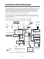
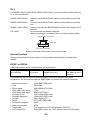
SYSTEM CONFIGURATIONS
All NavNet products incorporate a “network circuit board” to integrate each NavNet product
on board through an optional LAN cable (Ethernet 10BASE-T). Each NavNet product is
assigned an IP address to enable transfer of images between other NavNet products. For
example, video plotter pictures can be transferred to a radar and vice versa. Pictures
received via the NavNet may be adjusted at the receiving end.
The number of display units which may be installed depends on the number of network
sounders connected. For a system incorporating three or more NavNet products, a “hub” is
required to process data.
For one network sounder: one radar and three plotters, or four plotters
For two network sounders: one radar and two plotters, or four plotters
MODEL1824C
Antenna Unit
MODEL
1964C
MODEL
1954C
MODEL
1934C
MODEL
1944C
MODEL
1834C
Power Supply Unit
PSU-005
(MODEL 1954C)
Power Supply Unit
PSU-008
(MODEL 1964C)
AIS Interface
IF-1500AIS*
AIS transponder
* Not required for AIS
Transponder FA-150
GPS receiver
GP-320B/330B
or
Weather station
WS-200
Echo sounder
Navigator
Display unit
RDP-149
External buzzer
PC
VGA monitor
Remote display
Video equipment
ARPA
ARP-11
(Built-in)
Heading sensor
HUB
Rectifier
RU-3423
FA-30
AIS RECEIVER
Facsimile
Receiver
FAX-30
100/110/115/220/230 VAC 12 - 24 VDC*
1φ, 50/60 Hz*
: Standard
: Option
: Local supply
*: The power for the power supply unit
and display unit must be drawn from
the same power source.
Network
Sounder
ETR-6/10N
ETR-30N
Other NavNet unit
(GD-1920C, etc.)
NavNet system: MODEL1824C/1834C/1934C/1944C/1954C/1964C
iv
GPS receiver
GP-320B/330B
or
Weather station
WS-200
* Not required for AIS
Transponder FA-150
AIS transponder
External buzzer
AIS Interface
IF-1500AIS*
VGA monitor
Remote display
PC
Video equipment
ARPA
ARP-11
Display unit
RDP-149
HUB
Echo sounder
Navigator
Other NavNet Unit
(Model 1834C, etc.)
Facsimile
Receiver
FAX-30
FA-30
AIS RECEIVER
Network
Sounder
ETR-6/10N
ETR-30N
Rectifier
PR-62
12 - 24 VDC
100/110/115/220/230 VAC
1φ, 50/60 Hz
: Standard
: Option
: Local supply
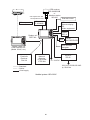
NavNet system: GD-1920C
v
Radar Antenna Unit,
GPS Receiver GP-320B/330B
OR
Weather Station WS-200
Radar Antenna Unit,
GPS Receiver GP-320B/330B
OR
Weather Station WS-200
RADAR
or
PLOTTER
RADAR
or
PLOTTER
Radar, plotter data
Radar, plotter data
Two-unit NavNet system
Radar Antenna Unit,
GPS Receiver GP-320B/330B
OR
Weather Station WS-200
Radar Antenna Unit,
GPS Receiver GP-320B/330B
OR
Weather Station WS-200
RADAR
or
PLOTTER
RADAR
or
PLOTTER
Radar data
Plotter data
HUB
Sounder data
Sounder data
Note: The picture disappears
10 seconds after the NavNet
cable is disconnected from a
"sub" NavNet display unit.
Facsimile
data
Network Sounder
ETR-6/10N
ETR-30N
(option)
Facsimile
Receiver
FAX-30
(option)
Network Sounder
ETR-6/10N
ETR-30N
(option)
Three-or-more unit NavNet system
vi
1. MOUNTING
NOTICE
Do not apply paint, anti-corrosive
sealant or contact spray to coating or
plastic parts of the equipment.
Those items contain organic solvents that
can damage coating and plastic parts,
especially plastic connectors.
1.1 Mounting the Display Unit
The display unit can be mounted on a tabletop, on the overhead or flush mounted in a
console or panel.
Table Top
Overhead
Hard Cover
Tabletop, overhead mounting method
1.1.1 Mounting considerations
When selecting a mounting location for the display unit, keep the following in mind:
Keep the display unit out of direct sunlight.
The temperature and humidity at the mounting location should be moderate and stable.
Locate the unit away from exhaust pipes and vents.
The mounting location should be well ventilated.
Mount the unit where shock and vibration are minimal.
Keep the unit away from electromagnetic field generating equipment such as motors and
generators.
• For maintenance and checking purposes, leave sufficient space at the sides and rear of
the unit and leave slack in cables. Minimum recommended space is shown in the outline
drawing for the display unit.
• A magnetic compass will be affected if the display unit is placed too close to it. Observe
the compass safe distances shown in the SAFETY INSTRUCTIONS to prevent
disturbance to the magnetic compass.
•
•
•
•
•
•
1-1
1.1.2 Mounting procedure
Tabletop, overhead mounting
Follow the procedure below to mount the display unit on a tabletop or the overhead.
1. Fix the hanger by using four tapping screws (5x20).
2. Screw knob bolts in display unit, set it to the hanger, and tighten the knob bolts.
3. Attach the hard cover to protect the LCD.
Display unit
Tapping screws (4 pcs.)
Knob bolts (2 pcs.)
Hanger
Tabletop, overhead mounting of display unit
Note: For the overhead mounting, reinforce the mounting location and secure the hanger,
with bolts, nuts and washers (local supply).
1-2
Flush mounting
Note: Use supplied pan head screws when the thickness of the bulkhead is from 11 to 14
mm. For bulkhead which exceeds 14 mm in thickness, the length of the pan head
screws should be bulkhead thickness (A) plus 7.8±1.2 mm. Also the length of B
should be max. 8 mm.
B A
Fixing screw, side view
1. Prepare a cutout in the mounting location whose dimensions are as shown below.
2. Attach the flush mount sponge to the display unit.
3. Fix the display unit by using six washer head screws M4x20. Refer to the outline
drawing at the back of this manual.
342+0.5
209+1
4.5
140+0.5
217+0.5
6-R2.25
335+1
Flush mounting of display unit
Note: When installing the display unit in a panel, attach the vinyl tube (ø6, local supply) to
the drain hole to allow moisture to escape. Then, fasten the tube to the drain hole with
a cable tie.
1-3
1.2 Mounting the Antenna Unit of MODEL1824C
1.2.1 Mounting considerations
When selecting a mounting location for the antenna unit, keep in mind the following points.
• Install the antenna unit on the hardtop, radar arch or on a mast on an appropriate
platform. (For sailboats, a mounting bracket is optionally available.) It should be placed
where there is a good all-round view with, as far as possible, no part of the ship’s
superstructure or rigging intercepting the scanning beam. Any obstruction will cause
shadow and blind sectors. A mast, for instance, with a diameter considerably less than
the width of the antenna unit, will cause only a small blind sector. However, a horizontal
spreader or crosstrees in the same horizontal plane would be a much more serious
obstruction; place the antenna unit well above or below it.
Antenna unit
Antenna unit
Antenna unit
Antenna unit
Typical antenna unit placement on sailboat and powerboat
• In order to minimize the chance of picking up electrical interference, avoid where possible
routing the antenna cable near other electrical equipment onboard. Also avoid running the
cable in parallel with power cables.
• Observe the compass safe distances mentioned in the SAFETY INSTRUCTIONS to
prevent interference to a magnetic compass.
1-4
1.2.2 Mounting procedure
1. Remove the mounting hardware from the bottom of the antenna unit: four each of hex
bolts (M10X20), spring washers and flat washers. Save the mounting hardware to use it
to fix the antenna unit to the mounting platform later on.
Stern
Bow
Screws
two screws on other side
Flat washer
Spring washer
Hex bolt (M10 x 20)
Antenna unit, showing location of mounting hardware
2. Construct a platform (wood, steel*, or aluminum) of 5-10 mm (recommended dimension)
in thickness referring to the outline drawing at back of this manual. Fasten the platform
to the mounting location. Next, position the mounting base on the platform so the cable
entrance faces the stern direction.
*: For steel platform take appropriate measures to prevent corrosion.
Note: When drilling holes in the platform, be sure they are parallel with the fore and aft
line.
3. Using the hex bolts, flat washers and spring washers removed at step 1, fasten the
mounting base to the platform. The torque should be between 19.6-24.5 N•m.
Note: Longer hex bolts (M10X25) are supplied with the installation materials. Use them
instead of the hex bolts removed earlier if the mounting platform thickness is
5–10 mm.
Transceiver
module
Efeective
thread
length:
12 mm
Antenna base
assy.
5 mm or under : M10x20
5-10mm:
M10x25
over 10 mm:
locally supplied bolts
Flat
washer
Spring
washer
Platform
Hex bolt
Apply silicone sealant.
(M10 x 25
or M10 x 20)
How to fasten the mounting base to platform
1-5
4. The mounting base is fitted with a snap holder, which may be used to hang the cover
after removal. Use the hole next to a screw hole inside the cover to hang it.
a) Unfasten the snap assy. with the string attached at the holder in the mounting base.
b) Unwind the string.
c) Attach the snap to a screw hole on the inside of the cover.
Note: Do not hang any other objects with the snap.
Snap holder
Remove and discard
the packing material.
Antenna unit, inside view
1-6
5. Unfasten the rotation detector cable from the cable clamps, referring to the figure on
page 1-10.
1 , c
2 and c
3 in the figure below) to dismount the shield plate,
6. Unfasten 16 screws (c
core case and core case cover.
Pan head screws
M3x10 2 pcs. 2
Core case cover
3
3
3
2
Core case
3
2
Pan head screws
M4x10 5 pcs. 3
Cable clamps
1
1
1
Shield plate
1
3
Rotation detector cable
1
1
V
G t
N
D
-V
G
1
OP
N
D
+
OP
3
G
IF N D
1
V
Pan head screws
M4x8 9 pcs. 1
1
3
3
3
Caution: Be careful not to pinch the rotation detector cable when remounting the shield
plate.
1-7
7. Pass the antenna cable with connector through the cable gland, gasket and cable
entrance of the antenna unit, and then tighten cable gland.
Note 1: Be sure the shrink tube on the antenna cable does not contact the gasket.
Note 2: Pinch the gasket tightly and insert it into the cable entrance. Confirm that the slit
in the gasket is completely closed after inserting it into the cable entrance.
Rubber gasket
Gasket
Cable Gland
Sectional view
Shrink tube
Close the gasket
tightly.
Rubber gasket
Do not allow
shrink tube to
contact gasket.
Mounting base
Gasket
Antenna cable
Antenna unit, inside view
8. Twist antenna connector cables at the position between the shrink tube and the cable tie,
and then attach EMI core (supplied) to cables as shown below. After attachment, shift
EMI core slightly to confirm that it does not pinch cables.
Attach EMI core.
Twist cables here.
Shrink tube
Cable tie
Gasket
Radome base
Location of EMI core
1-8
9. Attach connectors of the antenna cable to the locations shown in the figure below, and
then fasten a pan head screw M4x10 to fix shield cable and core case (removed at step
6.)
Pan head screws
M4x10 9 pcs.
J810
(13 pin)
J809
(4 pin)
J801
(9 pin)
Antenna unit, connector location and fixing the shield cable w/core case
10. Put the EMI core on the antenna cable into the core case attached at step 9, with the flat
side of the core facing downward.
EMI core
Core case
EMI core, putting into core case
11. Refasten the shield plate and core case cover with 15 screws. Be sure that the cable
from the rotation detector passes through the notch between the two cable ties.
Notch
How to pass the rotation detector cable
1-9
12. Pass the cable from the rotation detector through two cable clamps.
Rotation detector
Cable clamps
Cable tie
(Another should
be inside.)
Antenna unit, clamping the rotation detector cable
13. Follow the instructions on the label inside the mounting base to secure the snap assy.
14. Confirm that the rubber gasket is properly positioned and that the triangle mark on the
radome cover is aligned with the triangle mark on the mounting base, then tighten the
fixing screws for the cover. See the sectional view on page 1-8 for how to position the
rubber gasket.
Mounting the optional mounting bracket
A mounting bracket for fastening the antenna unit to a mast on a sailboat is optionally
available.
Contents of mounting bracket 2 kit Type: OP03-93, Code No.: 008-445-080
Part
Hex. bolt
Hex. bolt
Mounting plate
Support plate (1)
Support plate (2)
Bracket (1)
Bracket (2)
Fixing plate
Type
Qty
M4x12
Code No.
000-804-725
M8x20
03-018-9001-0
03-018-9005-0
03-018-9006-0
03-028-9101-0
03-028-9102-0
03-028-9103-0
000-805-707
100-206-740
100-206-780
100-206-790
100-206-810
100-206-820
100-206-830
8
1
1
1
1
1
2
4
Assemble the mounting bracket and fasten it to a mast. Fasten the antenna unit to the
bracket. For details, see the figure on the next page.
1-10
M8 x 20
Mounting plate
M8 x 20
Fixing plate
Bracket (1)
Support plate (2)
Bracket (2)
Support plate (1)
M8 x 20
M4 x 12
(A) Assembling the mounting bracket
M10 x 25 (supplied with antenna unit)
(B) Fastening antenna to mounting
bracket
How to assemble and mount the optional mounting bracket
1-11
1.3 Mounting the Antenna Unit of MODEL1834C
1.3.1 Mounting considerations
• See the mounting considerations for the MODEL1824C on page 1-4.
• Observe the compass safe distances mentioned in the SAFETY INSTRUCTIONS to
prevent deviation of the magnetic compass.
1.3.2 Mounting procedure
1. Open the antenna unit packing box carefully.
2. Unbolt the four bolts at the base of the radome cover to remove the cover.
Radome cover
Antenna unit
The mounting surface must be parallel with the waterline and provided with five holes
(four fixing holes and one cable entry) whose dimensions are shown in the outline
drawing at the back of this manual.
The unit is adjusted so a target echo returned from the bow direction will be shown on
the zero degree (heading line) position on the screen. When drilling holes, be sure they
are parallel with the fore and aft line.
3. Prepare a platform (wood, steel*, or aluminum) of 5 to 10 millimeters in thickness for the
antenna unit.
A mounting bracket for mounting the antenna unit on a sailboat mast is optionally
available. (Refer to page 1-16.) Find the cable entry on the radome base. Next, position
the radome base so the cable entry faces the stern direction. This alignment must be as
accurate as possible.
*: For steel platform, take appropriate measures to prevent corrosion.
Ship's bow
Cable
entry
4- 10 Holes
Flat washer
Spring washer
M10 x 25 Hex bolt
Platform
Antenna unit, cover removed
1-12
Antenna base plate
Effective
thread length
Gasket
Radome
25 mm
5 - 10 mm
Flat
washer
Spring
washer
Apply silicone sealant.
Platform
M10 x 25
Hex bolt
How to fasten the radome base to the mounting platform
Wiring and final preparations
4. Drill a hole of approx. 16 mm diameter through the deck or bulkhead to run the signal
cable between the antenna unit and the display unit. (To prevent electrical interference
avoid running the signal cable near other electrical equipment and in parallel with power
cables.) Pass the cable through the hole. Then, seal the hole with sealing compound for
waterproofing.
5. Remove three shield covers in the radome.
6. Remove the cable clamping plate by unfastening four screws and removing a gasket.
Screws
4 pcs.
Cable clamping plate
Shield cover
Screws
7 pcs.
Gasket
Shield cover
Screws
7 pcs.
Screws
6 pcs.
Shield cover
Antenna unit, inside view
7. Pass the cable through the hole at the bottom of the radome base.
8. Secure the cable with the cable clamping plate and gasket. Ground the shield wire by
one of the screws of the cable clamping plate.
1-13
9. Attach three connectors of the signal cable to respective receptacles as shown below.
to one of the screws
of the cable clamping plate
9-pin connector:
to J801 on MD-9208
4-pin connector:
to J802 on MD-9208
13-pin connector:
to J611 on IF-9214A
Signal cable, antenna unit side
J802
J801
MD-9208
Cable
entry
PTU-9335
J611
IF-9214A
RF unit
1-14
10. Bundle the cables with the EMI core (supplied) as shown below.
J801
J802
J805
MD-9208
J804
J806
J803
Cable
entrance
Cable
clamping plate
Motor
EMI core
E04SS251512
(Above cable
clamping
plate)
J1
J613
PTU-9335
J611
IF9214
IF9214A
EMI core
11. Fix the shield cover. Do not pinch the cable.
12. Attach the radome cover, aligning triangle mark on radome cover with that on radome
base.
Radome cover
Radome base
How to position the radome cover
13. Loosely fasten the radome fixing bolts. You will tighten them after confirming magnetron
heater voltage.
1-15
Mounting the optional mounting bracket
A mounting bracket for fastening the antenna unit for the MODEL1834C to a mast on a
sailboat is optionally available.
Contents of mounting bracket 1 (Type: OP03-92, Code No.: 008-445-070)
Part
Type
Code No.
Qty
Hex. bolt
M4X12
000-804-725
4
Hex. bolt
M8X20
000-805-707
8
Mounting plate
03-018-9001-0
100-206-740
1
Support plate (1)
03-018-9005-0
100-206-780
1
Support plate (2)
03-018-9006-0
100-206-790
1
Bracket (1)
03-018-9002-1
100-206-751
1
Bracket (2)
03-018-9003-1
100-206-761
1
Fixing plate
03-018-9004-1
100-206-771
2
Assemble the mounting bracket and fasten it to a mast. Fasten the antenna unit to the
bracket. For details, see the figure on page 1-11.
1-16
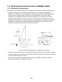
1.4 Mounting the Antenna Unit of
MODEL1934C/1944C/1954C/1964C
1.4.1 Mounting considerations
• The antenna unit is generally installed either on top of the wheelhouse or on the radar
mast on a suitable platform. Locate the antenna unit where there is a good all-round view.
Any obstruction will cause shadow and blind sectors. A mast for instance, with a diameter
considerably less than the horizontal beamwidth of the radiator, will cause only a small
blind sector, but a horizontal spreader or crosstrees in the same horizontal plane as the
antenna unit would be a much more serious obstruction; you would need to place the
antenna unit well above or below it.
• It is rarely possible to place the antenna unit where a completely clear view in all
directions is available. Thus, you should determine the angular width and relative bearing
of any shadow sectors for their influence on the radar at the first opportunity after fitting.
• To lessen the chance of picking up electrical interference, avoid where possible routing
the signal cable near other onboard electrical equipment. Also avoid running the cable in
parallel with power cables.
• A magnetic compass will be affected if the antenna unit is placed too close to it. Observe
the compass safe distances mentioned in the SAFETY INSTRUCTIONS to prevent
interference to a magnetic compass.
• Do not paint the radiator aperture, to ensure proper emission of the radar waves.
• When this radar is to be installed on larger vessels, consider the following points:
• The signal cable run between the antenna and the display units comes in lengths of
10 m, 15 m, 20 m and 30 m.
• Deposits and fumes from a funnel or other exhaust vent can adversely affect the
aerial performance and hot gases may distort the radiator portion. The antenna unit
must not be mounted where the temperature is more than 70°C.
As shown in the figure below, the antenna unit may be installed on the bridge, on a common
mast or on the radar mast.
(a) On bridge
(b) Common mast
1-17
(c) Radar mast
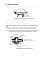
1.4.2 Mounting procedure
Referring to the outline drawing at the back of this manual, drill five holes in the mounting
platform: four holes of 15 mm diameter for fixing the antenna unit and one hole of 25-30 mm
diameter for the signal cable.
Fastening the radiator to the radiator bracket
For your reference, the antenna installation materials list appears in the packing list for this
unit at the back of this manual.
1. Remove the radiator cap from the radiator bracket.
2. Coat contacting surface between the antenna radiator and the radiator bracket with
silicone sealant as shown in the figure below.
ANTENNA RADIATOR
(bottom view)
RADIATOR BRACKET
(top view)
Groove
10mm
Radiator
Coat hatched area with
silicone sealant.
Coat grey area with
silicone sealant.
(MODEL 1934C)
(MODEL 1944C/1954C/1964C)
Coating the antenna with silicone sealant
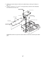
3.
4.
5.
6.
Coat threaded holes on the antenna radiator with silicone sealant.
Grease the O-ring and set it to the radiator bracket.
Lay the antenna radiator on the radiator bracket.
Coat the radiator fixing bolts (4 pcs.) with silicone sealant. Fasten the antenna radiator to
the radiator bracket with the radiator fixing bolts, flat washers and spring washers.
Antenna
radiator
Coat threaded
holes with silicone
sealant.
O-ring
Radiator bracket
Flat washer
Spring washer
Hex head bolt
(M8 x 30)
Coat bolts with
silicone sealant.
Fastening the radiator bracket to the antenna unit chassis
1-18
Mounting the antenna unit
The antenna unit can be mounted using the fixing holes on the outside (200 x 200 mm) or
inside (140 x 150 mm) the antenna unit.
Using outside fixing holes of the antenna housing
Use the hex head bolts (supplied) to mount the antenna unit as below.
1. Lay the corrosion-proof rubber mat (supplied) on the mounting platform.
Ground
terminal
Rubber
mat
Bow mark
Location of rubber mat
2. Lay the antenna unit on the mounting platform, orienting it as shown in below.
BOW
STERN
Antenna unit
CAUTION
Do not lift the Antenna unit by the
radiator; lift it by the housing.
The radiator may be damaged.
1-19
3. Insert four hex bolts (M12x60, supplied) and seal washers (Ф30, supplied) from the top
of the antenna housing, as shown below.
Hex bolt
Seal washer
Flat washer
Spring washer
Nut
Fixing the antenna unit chassis
4. Pass flat washers (M12, supplied), spring washers (M12, supplied) and nuts (M12,
supplied) onto hex bolts. Fasten by tightening nuts. Do not fasten by tightening the hex
bolts; seal washers may be damaged.
Seal washer
Antenna
unit
Mounting
platform
Silicone
sealant
Rubber mat
Flat washer
How to fasten antenna unit to mounting platform
5. Coat flat washers, spring washers, nuts and exposed parts of bolts with anticorrosive
sealant.
6. Prepare ground point in mounting platform (within 300 mm of ground terminal on
antenna unit) using M6 x 25 bolt, nut and flat washer (supplied).
7. Run the ground wire (RW-4747, 340 mm, supplied) between the ground terminal and
ground point.
1-20
8. Coat ground terminal and ground point with silicone sealant as shown below.
Hex bolt
Flat washer
Ground
wire
Silicone
sealant
Flat washer
Spring washer
Hex nut
OR
GROUND
POINT
Hex nut
Spring washer
Flat washer
Hex nut
Ground
wire
Weld here.
GROUND
TERMINAL
Silicone
sealant
Ground
wire
antenna
unit
How to coat ground point and ground terminal with silicone sealant
1-21
Using inside fixing holes of the antenna housing
This method requires removal of the RF unit in the antenna unit to access inside fixing
holes. Use hex head bolts, flat washers, spring washers and nuts (local supply) to mount
the antenna unit, confirming length of bolts.
1.
2.
3.
4.
5.
6.
Unfasten four scanner bolts on the cover to open the antenna unit.
Unplug connector connected between upper and lower chassis.
Separate upper chassis from lower chassis by removing two hex head bolts (M8x25).
Remove the board cover by unfastening four pan head screws.
Remove connector from RF unit.
Remove RF unit by unfastening four hex head bolts.
Hex head bolt
M8X25
2pcs.
Upper chassis
RFunit
Hex head bolt
M10X20 4pcs.
Spring Washer
M10 4 pcs.
Board cover
Pan head screw
M3X8 4pcs.
Square bushing
Lower chassis
Antenna unit chassis, upper chassis separated
7. Lay the corrosion-proof rubber mat (supplied) on the mounting platform.
8. Fasten the lower chassis to the mounting platform with hex head bolts, spring washers,
flat washers and nuts (local supply), and then coat flat washers, nuts and exposed parts
of bolts with silicone sealant. Cut a slit in the rubber bushing and insert bolt into the
bushing. Do not use seal washers.
9. Reassemble RF unit, cover and chassis.
10. Set four knob caps (supplied) into outside fixing holes.
11. Do steps 6-8 in “Outside fixing holes”.
1-22
Connecting the signal cable
Only the signal cable runs from the display unit (power supply unit in case of 1954C) to the
antenna unit. In order to minimize the chance of picking up electrical interference, avoid
where possible routing the signal cable near other onboard electrical equipment. Also, avoid
running the cable in parallel with power cables. Pass the cable through the hole and apply
sealing compound around the hole for waterproofing.
1. Open the antenna cover by loosening four bolts, and then fix the stay.
Stay
Cable gland
Bolt
Antenna unit chassis, cover opened
2. Unfasten the cable gland assembly (plate, gasket, flat washer).
3. Pass the signal cable with connector through the bottom of the antenna unit chassis.
Pass the cable through the gland assembly as shown below.
Bolt
4-M4X16
Plate
Gasket
Flat
washer
Passing the signal cable through the cable gland assembly
4. Fasten the crimp-on lug on the shield to one of the fixing bolts of the cable gland
assembly.
1-23
5. Position the signal cable so that no more than 4 cm of the sheath is exposed as shown
in the figure below. Tighten fixing bolts.
Tubing
Shield
Sheath
Bolt
Within 4 cm
Plate
Gasket
Flat
washer
CABLE GLAND
How to fix signal cable in cable gland
6. Unfasten four screws shown in the figure below.
Four screws
Antenna unit chassis, cover opened
7. Pass the signal cable through the cable protector.
Cable
protector
Antenna unit chassis, cover opened
1-24
8. Connect the signal cable to the RTB Board (03P9249 or 03P9250), referring to the
interconnection diagram and the figure below.
9. Attach three EMI cores to the signal cable as shown below.
RTB Board
J821 VH9P
J822 VH2P
J824 NH13P
Lead in
cable here.
J823 VH4P
EMI core
RFC-13
Clamp
Route cable along here.
Antenna unit chassis, cover opened
10. Fix the signal cable with the cable clamp.
11. Release the stay and close the cover. Loosely fasten the scanner bolts; you will have to
make some adjustments inside after completion of wiring.
Note: When closing the cover, set the gaskets to grooves in the bottom chassis, then
tighten bolts.
BOTTOM
CHASSIS
GROOVE
GASKET
SCANNER BOLT
Torque : 9.8 ±0.1 N . m
1-25
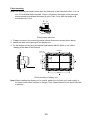
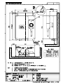
1.5 Mounting the Power Supply Unit
(MODEL 1954C/1964C)
1.5.1 Power supply unit PSU-005 (for MODEL 1954C)
A power supply unit is shipped with the MODEL1954C, because of its high power
consumption.
The power supply unit can be installed almost anywhere provided the location is dry,
well-ventilated, sufficient maintenance space is provided and is installed within 5 m (cable
length) from the display unit.
Note: Do not install the power supply unit on the overhead; install it on the deck or
bulkhead.
Service space: 150
Service
space: 100
Service
space: 100
Power supply unit
1-26
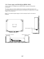
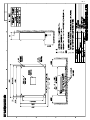
1.5.2 Power supply unit PSU-008 (for MODEL 1964C)
A power supply unit is shipped with the MODEL1964C, because of its high power
consumption.
The power supply unit can be installed almost anywhere provided the location is dry,
well-ventilated, sufficient maintenance space is provided and is installed within 5 m (cable
length) from the display unit.
Note: Do not install the power supply unit on the overhead; install it on the deck or
bulkhead.
Service space: 200 mm
Service space: 100 mm
Service space: 100 mm
1-27
This page is intentionally left blank.
1-28
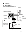
2. WIRING
2.1 Standard Wiring
All wiring is terminated at the rear of the display unit.
To antenna unit
of Model 1954C
MODEL1824C/1834C/1934C/1944C:
To antenna unit
Power supply unit
PSU-005
(MODEL 1954C)
Signal cable
MODEL1824C/1834C: MJ-B24LPF0002
MODEL 1934C/1944C: MJ-B24LPF0005
MJ-B24LPF0009-050
cable
Drain hole
(Allows moisture
to escape.)
12-24 VDC
Connect power
cable here.
12-24 VDC
Use the power source
which powers the display unit.
MJ-B24LPF0011-050
cable
OPTION
(remote display
VGA monitor)
Power supply unit
PSU-008
(MODEL 1964C)
Ground terminal
Connect ground wire
between here and
ship's ground.
To antenna unit
of Model 1964C
CAUTION
CAUTION
The display unit is shipped
with 15 A fuse.
Replace fuse with 7A
when using the equipment
in the following condition;
MODEL1824C/1834C/1934C/
1944C: ship's battery is 24 VDC
MODEL1954C/1964C/GD-1920C:
ship's battery is 12 or 24 VDC
Also, attach a label to the
fuse cover on power cable.
Use of wrong fuse can result
in damage to the equipment.
Ground the
equipment to
prevent
interference.
NETWORK
NavNet
equipment,
CU-200
(6P)
DATA4
DATA3
12-24 VDC
Use the power source
which powers the display unit.
DATA2
DATA1
NMEA (6P)
GPS receiver
Navigator,
Heading
AIS Trans., GPS-310B/320B
sensor
AIS Interface or NMEA (7P)
(AD or NMEA
format)
(6P)
Ext. buzzer/
PC/NMEA
IN (Echo sounder)
(7P)
Display unit, rear view
12-24 VDC
Connect the power cable to the POWER connector at the back of the display unit.
2-1
DJ-1
For MODEL1824C/1834C/1934C/1944C/1954C/1964C, remove the waterproofing cap from
DJ-1 port and discard it.
MODEL1824C/1834C:
MODEL1934C/1944C:
MODEL 1954C/1964C:
GD-1920C:
Connect the MJ-B24LPF0002 cable from the antenna unit to this
port.
Connect the MJ-B24LPF0005 cable from the antenna unit to this
port.
Connect the cable MJ-B24LPF0009 from the power supply unit to
this port.
Do not remove the waterproofing cap.
Wrap the connector nut and cap with vinyl tape as shown below.
Waterproofing cap (yellow)
Vinyl tape
Connector nut (for 24P)
Waterproofing cap and connector nut, sectional view
Ground terminal
Connect the ground wire (local supply, IV-2sq) between the ground terminal and ship’s
ground.
DATA1 to DATA4
Other equipments can be connected here as shown below.
DATA1 (7P)
GPS receiver
GP-310B/320B
DATA2 (6P)
NMEA sentence
(ex. Navaid)
DATA3 (6P)
Heading sensor (ex. SC-50/110)
(MODEL series only)
DATA4 (7P)
External buzzer,
PC, NMEA IN (Echo
sounder)
This equipment can receive the following NMEA 0183 format sentence from other
equipments. You will need the optional NMEA cable to connect with external equipment.
•
•
•
•
•
•
•
•
•
•
•
•
•
Own ship’s position:
Time:
Ship’s speed:
Other ship’s information:
Wind speed and angle:
Heading (True):
Heading (Magnetic):
Course:
Depth:
Destination waypoint:
Water temperature:
Target data:
DSC information:
GGA>RMC>RMA>GLL
ZDA>RMC
RMC>RMA>VTG>VHW
TTM
MWV>VWT/VWR
HDT>HDG>HDM>VHW
HDM>HDG>HDT>VHW
RMC>RMA>VTG
DPT>DBT>DBS>DBK
RMB
MTW
TLL (output from VHF radiotelephone FM-2721)
DSC>DSE (output from VHF marine transceiver FM-3000)
2-2
Connecting GP-310B/320B to DATA 2 port
GPS receiver GP-310B/320B can be connected to DATA 2 port as shown below when port
1 is not available.
You need a junction box and optional cable MJ-A6SPF0003-050 or MJ-A6SPF0009-100.
MJ-A6SPF0003-050
MJ-A6SPF0009-100
PROCESSOR UNIT
TD-A
TD-B
RD-A
RD-B
NC
SHIELD
1
2
3
4
5
6
DC power
supply
GP-310B/320B
JUNCTION BOX
DATA 2
WHT
BLK
YEL
GRN
1
2
3
4
5
6
7
WHT
BLU
YEL
GRN
RED
BLK
RD-A
RD-B
TD-A
TD-B
+ 12V
GND
Power supply
DC/DC CONVERTER
Type: Insulation
Connecting GP-310B/320B to DATA 2 port
NETWORK port
Other NavNet equipment should be connected to this port with the optional MJ-A6SPF0014
cable. Available equipments are shown below.
Radar
1824C-BB/1834C-BB/
1934C-BB/1944C-BB/
1834C-BB/1954C-BB
1964C-BB
Or other FURUNO
NavNet radar.
Plotter
Network sounder
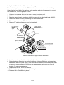
Other
GD-1920C-BB
ETR-6/10N
ETR-30N
2-3
HUB (used when
more than two NavNet
units are connected.)
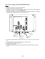
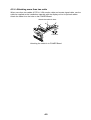
2.2 External Buzzer (optional supply)
The optional external buzzer provides a louder alert when the alarm is violated.
External buzzer
Type: OP03-136
Code no.: 000-086-443
Further, you need the optional cable assy MJ-A7SPF0007-050 (w/7P connector, 5 m, code
no. 000-144-418).
1. Attach the MJ-A7SPF0007-050 cable assy (option) to the DATA 4 port at the rear of the
display unit.
2. Cut the XH connector at the end of the external buzzer cable with appropriate length.
3. Solder the cables made at step 2 with MJ-A7SPF0007-050 cable as shown below.
Red
Soldering
MJ-A7SPF0007-050
External buzzer
Black
Other cable should be cut off,
and wrap here with tape.
Connection of external buzzer and display unit
using cable assy type MJ-A7SPF0007-050 cable
4. Attach the buzzer to the mounting location with the double-sided tape or two tapping
screws (3x15 or 3x20, local supply).
2-4
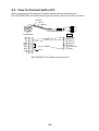
2.3 How to Connect with a PC
When connecting with the personal computer, prepare the optional cable assy
MJ-A7SPF0007-050 and D-sub 9 pins plug (local supply), and connect them as follows.
SHIELD
BLUE
WHITE
5
1
9
MJ-A7SPF0007-050
6
D-SUB 9PIN
CD
RD
TD
DTR
GND
DSR
RTS
CTS
RI
1
2
3
4
5
6
7
8
9
DATA4
WHITE
BLUE
SHIELD
short
1
2
3
4
5
6
7
TD_DT
RD_DT
RD3_A
RD3_B
+12V
EXT BUZZ
GND
MJ-A7SPF0007-050 cable connection for PC
2-5
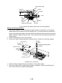
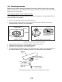
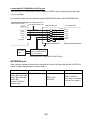
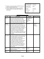
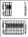
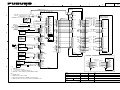
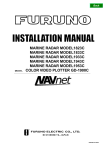
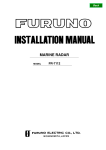
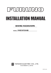
2.4 Wiring the Power Supply Unit
(MODEL 1954C/1964C)
2.4.1 Power supply unit PSU-005 (MODEL1954C)
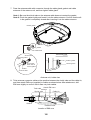
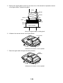
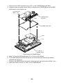
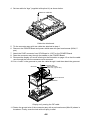
1. Unfasten three M4 screws to remove the cable clamp.
2. Unfasten six M4 screws to remove the cover.
3. Attach the VL connector of the power supply cable VL3P-VV-S2X2C-AA050 (supplied as
installation materials) to J1 on the POWER Board.
4. Attach the VH and NH connectors of MJ-B24LPF0009-050 cable (supplied as
installation materials) to these locations: VH9, J3; VH4, J4, NH13, J5.
POWER Board
19P1006
J1
ANT (J8)
J4
J3 V J5
H
V 4 N
H
H
13
9
Signal cable
(to antenna unit)
VL-3
Ground
terminal
(Wing bolt)
Slot
(small)
Cable tie
(if necessary)
Shield
Slot
VL3P-VV-S2X
(large)
MJ-B24
2C-AA050
LPF0009-050
cable
(to 12-24 VDC) cable
(to display
unit)
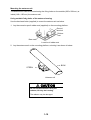
Power supply unit, cover removed
5. Lay two cables on the slots referring to the figure above.
To prevent strain to the cable MJ-B24LPF0009-050, fasten a cable tie (local supply) at the
position shown above.
6. Reattach the cover (removed at step 2).
7. Reattach the cable clamp.
8. Connect the antenna cable to the ANT port on the power supply unit.
9. Connect a ground wire (local supply, IV-2sq) between the ground terminal and ship’s
ground.
2-6
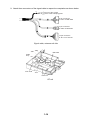
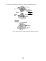
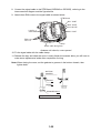
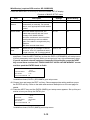
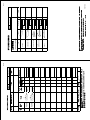
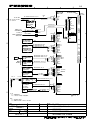
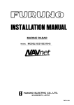
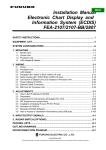
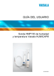
2.4.2 Power supply unit PSU-008 (MODEL1964C)
Cabling
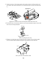
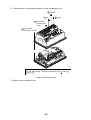
1. Unfasten four screws to remove the cable clamp.
2. Unfasten four screws to remove the cover.
3. Attach the VL connector of the power supply cable VL3P-VV-S2X2C-AA050 (supplied as
installation materials) to J1 on the POWER Board.
4. Attach the VH and NH connectors of MJ-B24LPF0011-050 cable (supplied as installation
materials) to these locations: VH9, J3; VH4, J4, NH13, J5.
POWER Board 03P9419
J11
V
H
2
J4
J13
V
H
4
V
H
5
J3
J1 3P
V
H
9
VL3P-VV-S2X
2C-AA050
cable
(to 12-24 VDC)
J5
N
H
13
J12
V
H
1
0
J14
N
H
1
4
Ground
terminal
MJ-B24
LPF0011-050
cable
(to display unit)
Antenna cable
RW-9771
(03S9771)
5. Connect the antenna cable to these locations: VH2, J11, VH10, J12; VH5, J13, NH14,
J14.
6. Lay three cables in respective slots referring to the figure above.
7. Reattach the cover (removed at step 2).
8. Reattach the cable clamp.
9. Connect a ground wire (local supply, IV-2sq) between the ground terminal and ship’s
ground.
2-7
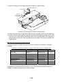
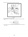
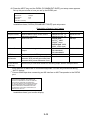
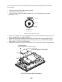
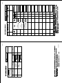
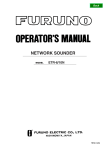
Jumper block, slide switch setting
The jumper block JP1 and slide switch S112 on the PWR board (03P9419) must be set
according to radar model. Open the unit, locate JP1 and S112 and set them as below.
Jumper block JP1
("open" for this radar;
leave the dummy
connector attached)
Slide switch S112
(Downward position
for this radar)
FR-8252
S
S112
T
MODEL1964C
Power supply unit, inside view
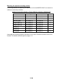
Jumper block, slide switch
JP1
S112
Function
Enables/disables motor slow start circuit.
TUNE voltage selector (0-12 V, 0-32 V)
2-8
Setting
Open (enable)
Downward position
(0-32 V)
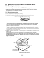
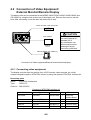
2.4.3 Power requirement, replacement of fuses
Power requirement
The power for the power supply unit and display unit must be drawn from the same power
switch on the power terminal board.
Other Equipment
(ex. GPS, E/S etc.)
Display unit
Power supply unit
PSU-008
Other Equipment
(ex. GPS, E/S etc.)
Other Equipment
(ex. GPS, E/S etc.)
Power supply unit
PSU-005
Other Equipment
(ex. GPS, E/S etc.)
Other Equipment
(ex. GPS, E/S etc.)
Power terminal board
CAUTION
The display unit and antenna should be
powered from the same power source.
This should be done so the antenna will
rotate only when the display unit is
turned on.
Replacement of fuses
The power supply unit is shipped with 15 A fuse. Replace fuse with 7 A (supplied) when the
ship’s battery is 12 or 24 VDC.
2-9
This page is intentionally left blank.
2-10
3. SETTING UP THE EQUIPMENT
3.1 Setting up with the Installation Wizard
After you have installed the equipment, set up the equipment with the installation wizard.
The wizard allows you to easily set up the NavNet network (choose source of radar,
sounder and auxiliary), GPS, ports, etc.
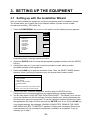
1. Press the POWER/BRILL key to turn on the power, and the following screen appears.
INSTALL
WIZARD
LANGUAGE
▲
NEXT
~
ENGLISH
{ FRANCAIS
{ DEUTSCH
{ ITALIANO
{ PORUTGES
{ ESPANOL
{ DANSK
{ SVENSKA
{ NORSK
▼
EDIT
EXIT
Installation wizard, language selection window
2. Rotate the ENTER knob to choose the appropriate language and then push the ENTER
soft key.
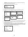
3. A dialog box asks you if you want to start the simulation mode, which provides
simulated operation of the equipment.
4. Press the CLEAR key to skip the simulation mode. Then, the SELECT MODE window
appears. When confirming connections only, the simple check mode is useful.
SELECT MODE
▲
~
INST. WIZARD
INST. MODE
{ SIMPLE CHECK MODE
{ NORMAL MODE
▼
{
CHANGE OR CONFIRM THE ITEMS SHOWN
ABOVE. THE PUSH [NEXT] WHEN DONE.
5. Confirm that INST. WIZARD is selected, and then push the ENTER soft key.
A diagnostic test is conducted and then the chart disclaimer message appears.
6. You are then asked “LOAD SETTING DATA FROM CARD?”. This allows you to use the
set up this NavNet unit with the settings of another NavNet unit, thereby shortening the
time required to set up the equipment. To use the settings of another NavNet unit, insert
the appropriate SD card in the slot and push the ENTER knob. If not, hit the CLEAR key.
If you loaded settings, the message “LOADING COMPLETED. REMOVE THE CARD
AND PRESS ANY KEY TO RESTART” appears if loading was successful. Remove the
card and press any key to restart the equipment; installation is completed. To set up
manually, go to step 7.
3-1
CAUTION: Ensure that the settings to be loaded are compatible with this NavNet unit.
Improper setting will damage the equipment.
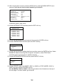
7. The screen for set up of units of measurement appears.
RANGE UNIT
DEPTH UNIT
TEMPERATURE UNIT
WIND UNIT
LOCAL TIME OFFSET
LOCAL TIME OFFSET
AIR PRESSURE UNIT
nm, kt
ft
˚F
kt
+00:00
+00:00
hpa
Installation wizard, units of measurement
8. Choose an item and then press the EDIT soft key. One of the following windows
appears.
RANGE/SPEED UNIT
DEPTH UNIT
TEMPERATURE UNIT
▲
▲
▲
{
{
{
nm, kt
~ km, km/h
{ sm, mph
{ nm & yd, kt
{ nm & m, kt
{ km & m, km/h
{ sm & yd, mph
▼
m
~ ft
{ fa
{ PB
▼
~
°C
°F
▼
AIR PRESSURE UNIT
LOCAL TIME OFFSET
▲
~
hpa
mbar
{ mmHg
{ inHg
▼
{
WIND UNIT
▲
+ 00:00
{
kt
~ km/h
{ MPH
{ m/s
▼
9. Choose unit of measurement desired and then press the ENTER soft key. LOCAL TIME
OFFSET allows you to use local time (instead of UTC time). Set the time difference
between local time and UTC time.
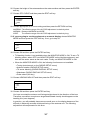
10. After you have chosen units of measurement, press the NEXT soft key, and the
NETWORK SETUP menu appears. This is where you set up your NavNet network. See
the illustration on the next page for typical network setup. If you have no other NavNet
devices installed, press the NEXT key and go to step 13.
DEVICE NUMBER
(HOST NAME
(IP ADDRESS
1
NAVNET-1)
172.031.003.003)
RADAR SOURCE
1
SOUNDER SOURCE
ETR0
AUX SOURCE
AUX1
FOR FURTHER DETAILS,
PLEASE REFER TO THE
INSTALLATION MANUAL
Installation wizard, network setup
3-2
11. Choose appropriate item and then press the EDIT soft key. One of the following displays
appears depending on your selection.
DEVICE NUMBER
RADAR SOURCE
▲
▲
{
{
1 (IP:172.031.003.001)
~ 2 (IP:172.031.003.002)
{ 3 (IP:172.031.003.003)
{ 4 (IP:172.031.003.004)
▼
1 (IP:172.031.003.001)
2 (IP:172.031.003.002)
{ 3 (IP:172.031.003.003)
{ 4 (IP:172.031.003.004)
{ NO CONNECT
▼
~
SOUNDER SOURCE
▲
{
~
{
{
{
{
{
{
{
{
{
▼
ETR0 (IP:172.031.092.001)
ETR1 (IP:172.031.092.011)
ETR2 (IP:172.031.092.012)
ETR3 (IP:172.031.092.013)
ETR4 (IP:172.031.092.014)
ETR5 (IP:172.031.092.015)
ETR6 (IP:172.031.092.016)
ETR7 (IP:172.031.092.017)
ETR8 (IP:172.031.092.018)
ETR9 (IP:172.031.092.019)
OFF
AUX SOURCE
▲
~
AUX1 (IP:172.031.008.001)
AUX2 (IP:172.031.008.002)
{ AUX3 (IP:172.031.008.003)
{ AUX4 (IP:172.031.008.004)
{ OFF
▼
{
12. Choose appropriate setting and then press the ENTER soft key. If you set DEVICE NO.
or RADAR SOURCE, turn the power on and off again at the completion of the
installation wizard.
Radar Antenna
Echo
Sounder
ETR0
(default)
HUB
10-inch
display
Device 1
7-inch
display
Device 2
7-inch
display
Device 3
FAX30
AUX1
(default)
Device Number - 1
Device Number - 2
Device Number - 3
Radar Source - 1
Radar Source - 1
Radar Source - 1
Sounder Source - ETR0
Sounder Source - ETR0
Sounder Source - ETR0
Aux Source - AUX1
Aux Source - AUX1
Aux Source - AUX1
3-3
13. After choosing ALL sources, press the NEXT soft key, and the RADAR SETUP menu
appears. If you do not have a radar installed, go to step 33.
ANTENNA TYPE
HEADING DATA
ANTENNA ROTATION
RADAR OPTIMIZATION
TIMING ADJUST
M. B. SUPRRESSION
RADAR ANTENNA HEIGHT
STC CURVE
MONITOR MODE
HEADING ADJUST
A
MAGNETIC
ROTATE
OFF
OFF
OFF
MEDIUM (3-10m, 10-33ft)
MEDIUM
OFF
OFF
Installation wizard, radar setup
14. Choose ANTENNA TYPE and then press the EDIT soft key.
ANTENNA TYPE
▲
{
A (MODEL 1824C)
B (MODEL 1834C)
{ C (MODEL 1934C)
{ D (MODEL 1944C)
{ E (MODEL 1954C)
{ F (MODEL 1964C)
~
▼
15. Choose the appropriate antenna type and then press the ENTER soft key.
16. Choose HEADING DATA and then press the EDIT soft key.
HEADING DATA
▲
{
~
MAGNETIC
TRUE
▼
17. Choose the appropriate heading data format and then press the ENTER soft key. Select
MAGNETIC when connecting with a magnetic compass, or select TRUE when
connecting with a gyrocompass or satellite compass.
18. Choose ANTENNA ROTATION and then press the EDIT soft key.
ANTENNA ROTATION
▲
~
{
▼
ROTATE
STOP
19. Choose ROTATE (other than MODEL 1954C or 1964C) or STOP (MODEL 1954C or
1964C) and then press the ENTER soft key.
For the MODEL 1954C or 1964C, follow the procedure in the illustration at the top of
the next page. For other models, go to step 20.
3-4
Tuning Power Supply Unit for MODEL 1954C
1. Choose TIMING ADJUST and then press the EDIT soft
key.
2. Choose ON and then press the ENTER soft key.
3. You are asked if you want to transmit; push the ENTER
knob.
4. Use the RANGE key to choose the 6nm range.
5. Press the RETURN soft key.
6. Open the power supply unit cover and flip switch
SW1 on the POWER Board upward (tuning position).
7. Adjust potentiometer R36 clockwise so that CR13 LED
lights in the highest brilliance.
8. Flip switch SW1 switch downward (default setting).
9. Set ANTENNA ROTATION to ROTATE.
10. Reassemble the cover of the power supply unit.
11. Go to step 20.
POWER Board
19P1006
TP5 TP2
CR13
R36
Upward
SW1
Downward
CR113
Tuning Power Supply Unit for MODEL 1964C
1. Follow step 1-5 above.
2. Open the power supply unit cover and flip the switch
S111 on the POWER Board to the upward (TUNE ADJ)
position.
3. Adjust potentiometer R123 clockwise so that LED
R123
CR113 lights in the highest brilliance.
4. Flip the switch S111 to the downward (END ADJ)
position.
5. Set ANTENNA ROTATION to ROTATE.
6. Reassemble the cover of the power supply unit.
7. Go to step 20.
S111
TUNE ADJ
S
S111
T
END ADJ
20. Choose RADAR OPTIMIZATION and then press the EDIT soft key.
RADAR OPTIMIZATION
▲
{
~
ON
OFF
▼
21. Choose ON and then press the ENTER soft key. Then, the radar’s video and tuning are
automatically adjusted.
22. After tuning has been completed, choose TIMING ADJUST and then press the EDIT soft
key.
TIMING ADJUST
▲
{
~
ON
OFF
▼
3-5
This adjustment ensures proper radar performance, especially on short ranges. The
radar measures the time required for a transmitted echo to travel to the target and return
to the source. The received echo appears on the display based on this time. Thus, at
the instant the transmitter is fired, the sweep should start from the center of the display
(sometimes called sweep origin.)
A trigger pulse generated in the display unit goes to the antenna unit through the signal
cable to trigger the transmitter (magnetron). The time taken by the signal to travel up to
the antenna unit varies, depending largely on the length of signal cable. During this
period the display unit should wait before starting the sweep. When the display unit is
not adjusted correctly, the echoes from a straight local object (for example, a harbor wall
or straight pier) will not appear with straight edges – namely, they will be seen as
“pushed out” or “pulled in” near the picture center. The range of objects will also be
incorrectly shown.
(1) Target
pulled
(2) Correct
(3) Target pushed
outward
Examples of improper and correct sweep timing
a) Choose ON and then press the ENTER soft key.
b) Transmit on the shortest range and confirm that gain and A/C SEA are properly
adjusted.
c) Visually select a target which forms straight line (harbor wall, straight piers).
d) Rotate the ENTER knob to straighten the target selected at step b), and then press the
ENTER knob to finish.
23. Choose M. B. SUPPRESSION and press the EDIT soft key.
M. B. SUPPRESSION
▲
{
~
ON
OFF
▼
24. Choose ON and then press the ENTER soft key. Main bang is the “black hole” which
appears at the display center on short ranges. Rotate the ENTER knob to suppress the
main bang. After adjusting, press the RETURN key.
25. Choose RADAR ANTENNA HEIGHT and then press the EDIT soft key.
RADAR ANT. HEIGHT
{
~
{
HIGH (>10m, 33ft)
MEDIUM (3-10m, 10-33ft)
LOW (<10m, 33ft)
3-6
26. Choose the height of the antenna above the water surface and then press the ENTER
soft key.
27. Choose STC CURVE and then press the EDIT soft key.
STC CURVE
▲
{
~
{
NARROW
NORMAL
WIDE
▼
28. Choose appropriate STC curve setting and then press the RETURN soft key.
NARROW: The effective range of the A/C SEA adjustment is relatively short.
NORMAL: Between NARROW and WIDE.
WIDE:
The effective range of the A/C SEA adjustment is relatively long.
29. If you are going to use the equipment as a remote display, choose MONITOR
MODE and then press the EDIT soft key. If not, go to step 31.
MONITOR MODE
▲
{
~
ON
OFF
▼
30. Choose ON and then press the ENTER soft key.
• TX blanking function is not available when the MONITOR MODE is ON. To set a TX
blanking sector, select OFF from MONITOR MODE on the NavNet equipment, and
then set the sector same as the main radar. Finally, set MONITOR MODE to ON.
• When the MONITOR MODE is ON, the following functions are not available.
• Tuning (auto/manual, on the RADAR SETUP menu)
• Antenna rotation (RADAR SETUP menu)
• TX sector blanking (RADAR DISPLAY SETUP menu)
• Watchman (RADAR DISPLAY SETUP menu)
• Pulse select (Soft key)
31. Choose HEADING ADJUST and then press the EDIT soft key.
HEADING ADJUST
▲
{
~
ON
OFF
▼
32. Choose ON and then press the ENTER soft key.
You have mounted the antenna unit facing straight ahead in the direction of the bow.
Therefore, a small but conspicuous target dead ahead visually should appear on the
heading line (zero degrees).
In practice, you will probably observe some small error on the display because of the
difficulty in achieving accurate initial positioning of the antenna unit. The following
adjustment will compensate for this error.
3-7
a) Set ship’s heading toward a suitable target (for example, ship or buoy) at a range
between 0.125 and 0.25 nautical mile.
b) Rotate the ENTER knob to bisect the target with the EBL and press the SET soft key
c) Press the RETURN soft key.
d) As a final test, move the boat towards a small buoy and confirm that the buoy shows up
dead ahead on the radar when it is visually dead ahead.
33. The next step is to set up external equipment. Press the NEXT soft key to show the NAV
SETUP menu.
POSITION SOURCE
FURUNO BB GPS
SPEED (STW) SOURCE
ETR
TEMPERATURE SOURCE
ETR
DETPH SOURCE
ETR
STW CALIBRATION
+00%
TEMP CALIBRATION
+00.0°F
DEPTH CALIBRATION
+00ft
WIND AVERAGING
001 seconds(s)
WIND DIRECTION OFFSET S000.0°
WIND SPEED CALIBRATION +00%
WIND (MWV) SOURCE
FURUNO BB GPS
STW
TEMP
DEPTH
99.5ft
12.3 kt
56.3°F
WIND SPEED WIND DIR
131°
1.2 kt
Page 1
AIR TEMPERATURE SOURCE FURUNO BB GPS
AIR PRESSURE SOURCE
FURUNO BB GPS
STW
12.3 kt
WIND SPEED
1.2 kt
TEMP
56.3°F
DEPTH
99.5ft
WIND DIR
131°
Page 2
Installation wizard, nav setup
34. Choose item and press the EDIT soft key.
35. Choose appropriate setting and then press the ENTER soft key. Refer to the table on
next page for description of each item.
3-8
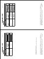
NAV SETUP menu description
Item
Position Source
Description
Chooses source of position data.
Speed Source
Temperature
Source
Chooses source of speed data
Chooses source of water
temperature data.
Depth Source
Chooses source of depth data.
STW Calibration
Calibrates NMEA speed data. Enter
amount in percentage.
Calibrates NMEA temperature data.
Enter offset to correct NMEA
temperature data.
Calibrates NMEA depth data. Enter
offset to correct NMEA depth data.
Temp Calibration
Depth Calibration
Wind Averaging
Wind Direction
Offset
Wind Speed
Calibration
Wind (MWV)
Source
Enter a value to smooth wind
speed/direction data. Ship’s bow is
referenced to smooth wind vector
movement.
Offsets wind direction data.
Settings (Default in bold)
FURUNO BB GPS: GPS Receiver
GP-320B/330B or Weather sensor WS-200
GP: GPS navigator (via NETWORK or
NMEA port)
LC: Loran C navigator (via NETWORK or
NMEA port)
ALL: Multiple navaid connection (via
NETWORK or NMEA port)
ETR (NavNet sounder), NMEA
ETR, NMEA. Select ETR to show water
temperature data fed from the network
sounder.
ETR, NMEA. Select ETR to show depth
data fed from the network sounder.
-50 to +50%, 00
-20.0°C to +20.0°C (or equivalent in °F),
00.0°C
-15 to +90 ft (or equivalent in m, fa or P/B).
00 ft
001-600 s, 001 s
S180°-P180°, S000.0°
Offsets NMEA wind speed data.
Enter amount in percentage.
Chooses source of wind data.
-50 to +50%, 00%
Air Temperature
Source
Chooses source of air temperature
data.
FURUNO BB GPS, NMEA: Select
FURUNO BB GPS to show air temperature
data fed from the WS-200.
Air Pressure
Source
Chooses source of air pressure
data.
FURUNO BB GPS, NMEA: Select
FURUNO BB GPS to show air pressure
data fed from the WS-200
FURUNO BB GPS, NMEA: Select
FURUNO BB GPS to show wind data fed
from the WS-200.
36. After setting up, press the NEXT soft key, and the GPS SETUP menu appears. This
menu setups the built-in GPS receiver.
3-9
37. Choose an item and press the EDIT soft key to
show corresponding window.
38. Choose setting and then press the ENTER
soft key. Refer to the table which follows for
description.
GEODETIC DATUM
POSITION SMOOTHING
SPD/CSE SMOOTHING
LATITUDE OFFSET
LONGITUDE OFFSET
DISABLE SATELLITE
LATITUDE
LONGITUDE
ANTENNA HEIGHT
GPS FIX MODE
COLD START
WGS-84
000 second (s)
005 second (s)
0.000'N
0.000'E
-- -- -45°35.000'N
125°00.000'W
005 m
2D/3D
NO
Installation wizard, GPS setup
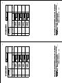
GPS SETUP menu description
Item
Description
Settings
Geodetic
Datum
Your equipment is preprogrammed with most
of the major chart systems of the world.
Although the WGS-84 system, the GPS
standard, is now widely used other categories
of charts still exist. Select the chart system
used, not the area where your boat is sailing.
Use the trackball
or ENTER knob
to select
appropriate
chart.
WGS-84
Position
Smoothing
When the DOP or receiving condition is
unfavorable, the GPS fix may change, even if
the vessel is dead in water. This change can
be reduced by smoothing the raw GPS fixes.
A setting between 000 to 999 is available. The
higher setting the more smoothed the raw
data, however too high a setting shows
response time to change in latitude and
longitude. This is especially noticeable at high
ship’ speeds. Increase the setting if the GPS
fix changes.
During position fixing, ship’s velocity (speed
and course) is directly measured by receiving
GPS satellite signals. The raw velocity data
may change randomly depending on
receiving conditions and other factors. You
can reduce this random variation by
increasing the smoothing. Like with latitude
and longitude smoothing, the higher the
speed and course smoothing the more
smoothed the raw data. If the setting is too
high, however, the response to speed and
course change slows. For no smoothing,
enter all zeros.
Offsets latitude position to further refine
position accuracy. Use the N <- - > S soft key
to switch coordinate.
As above but for longitude. Use the W < - - >
E soft key to switch coordinate.
0-999 sec
0 sec (no
position
smoothing)
0-999 sec
5 sec
9.999’S –
9.999’N
0.0’ (no offset)
9.999’E –
9.999’W
0.0’ (no offset)
Spd/Cse
Smoothing
Latitude
Offset
Longitude
Offset
3-10
Default Setting
Item
Description
Settings
Default Setting
None
Disable
Satellite
Every GPS satellite is broadcasting
abnormal satellite number (s) in its
Almanac, which contains general orbital
data about all GPS satellites, including
those which are malfunctioning. Using
this information, the GPS receiver
automatically eliminates any
malfunctioning satellite from the GPS
satellite schedule. However, the
Almanac sometimes may not contain
this information. If you hear about a
malfunctioning satellite from another
source, you can disable it manually.
Enter satellite number (max. 3
satellites) in two digits and press the
ENTER soft key.
Latitude
Set initial latitude position after cold
start. Use the N < - -> S soft key to
switch coordinate.
90°S - 90°N
45°35.000’N
Longitude
Set initial longitude position after cold
start. Use the W <- - > E soft key to
switch coordinate.
180°E – 180°W
125°00.000W
Antenna
Height
Enter the height of the GPS antenna
unit above sea surface.
0-99 m
5m
Fix Mode
Choose position fixing method: 2D
(three satellites in view), 2D/3D (three
or four satellites in view whichever is
greater).
2D, 2D/3D
2D/3D
Cold Start
Clears the Almanac to receive the latest
Almanac.
No, Yes
No
3-11
WAAS setup (requires GPS receiver GP-320B/330B)
Press the WAAS SETUP soft key to show the WAAS SETUP display.
Contents of WAAS SETUP menu
Item
Description
Settings
Default Setting
WAAS Mode
Select ON to use the WAAS mode.
On, Off
Off
WAAS
Search
WAAS satellite can be searched
automatically or manually. For manual
search, enter appropriate WAAS satellite
number.
Auto, Manual
Auto
WAAS Alarm
When the WAAS signal is lost, the
audible alarm sounds with the visual
message “NO WAAS SIGNAL.”
On, Off
Off
00 to 27, 99
02
On: Alarm continues to sound until the
WAAS positioning mode is available
again or the alarm is recognized by key
operation.
Off: Alarm sounds three times.
Corrections
Data
Selects the type of message for WAAS
correction. Use “00” (operational status)
in North America; “02” in other locations.
39. After you have finished setting up the GPS receiver, it’s now time to set up external
equipment. Press the NEXT soft key to show the DATA1 (GPS/NMEA) port setup menu.
It is only necessary to set up ports which you are going to use; skip unnecessary steps.
If you do not have external equipment connected to the NavNet, press the NEXT
key several times to show the “FINISH AND EXIT INSTALLATION WIZARD” screen
and then push the ENTER knob to finish.
OUTPUT FORMAT
NMEA0183
Ver 2.0
LAT/LON FORMAT
DD'MM.MMM'
XTE FORMAT
X. XX
OUTPUT DESTINATION NO
Installation wizard, DATA1 (GPS/NMEA) port setup menu
40. Choose item and press the EDIT soft key. Choose appropriate setting and then press
the ENTER soft key. Refer to the table and sentence description on the next page for
details.
41. Press the NEXT key, and the DATA2 (NMEA) port setup menu appears. Set up this port
similar to how you set up the DATA1 port.
OUTPUT FORMAT
NMEA0183
Ver 2.0
BAUD RATE
4800bps
LAT/LON FORMAT
DD'MM.MMM'
XTE FORMAT
X. XX
OUTPUT DESTINATION NO
Installation wizard, DATA2 (NMEA) port setup menu
3-12
42. Press the NEXT key, and the DATA4 (PC/NMEA/EXT. BUZZ) port setup menu appears.
Set up this port similar to how you set up the DATA2 port.
NMEA OUTPUT FORMAT NMEA VER. 2.0
BAUD RATE
4800 bps
BIT LENGTH
8 bits
STOP BIT
1 bit
(CONTROL: Xon/Xoff)
Installation wizard, DATA4 (PC/NMEA/EXT. BUZZ) port setup menu
Description of items in “port” menus
Item
Description
Settings
Default Setting
Output Format
Selects NMEA output version for the
equipment connected.
NMEA0183 Ver. 1.5,
NMEA0183 Ver. 2.0
DATA2 port:
AUTO*1, 4800,
38400*2 (bps)
DATA4 port: 4800,
9600, 19200 (bps)
DD°MM.MM’,
DD°MM.MMM’,
DD°MM.MMMM’
NMEA0183 Ver.
2.0
Baud Rate
Sets baud rate.
Lat/Lon Format
Selects latitude/longitude format to
output.
XTE Format
Output
Destination
Selects number of XTE digits to output.
Selects whether to output route (data
sentence RTE) and waypoint data (data
sentence WPL) when destination is set.
X. XX, X. XXX
Yes, No
X. XX
No
PORT MNITR
(soft key)
Use this key to view which sentences are being output. See the example below.
4800 bps
DD°MM.MMM’
*1 Auto detection of baud rate of connected equipment. For use only with device having
“AUTO” feature.
2
* Choose 38400 bps when connecting an AIS Interface or AIS Transponder to the DATA2
port.
$GPGLL,3415.2345,N,13520.5301,E,152500.00
,A*E7<CR><LF>$GPGLL,3415.2345,N,135
20.5301,E,152500.00,A*E7<CR><LF>$GPGLL
,3415.2345,N,13520.5301,E,152500.00,A*
E7<CR><LF>$GPGLL,3415.2345,N,13520.530
1,E,152500.00,A*E7<CR><LF>$GPGLL,3415.
2345,N,13520.5301,E,152500.00,A*E7<CR>
<LF>$GPGLL,3415.2345,N,13520.5301,E,15
2500.00,A*E7<CR><LF
Installation wizard, port monitor display
3-13
43. Press the NEXT soft key, and the NMEA sentence selection window (for network)
appears.
AAM
APB
BOD
BWR
DPT
GGA
GLL
GTD
MTW
RMA
RMB
RMC
VHW
VTG
WPL
XTE
ZDA
HDT
HDG
MWV
ZTG
----------------------
Installation wizard, NMEA sentence selection window
44. Choose sentence to process and press the ON/OFF soft key to show ON or “- -“ (OFF)
as appropriate.
45.Press the NEXT soft key and the message “FINISH AND EXIT INSTALLATION WIZARD.
ARE YOU SURE?” appears. Press the ENTER knob to finish the installation wizard.
This concludes the Installation Wizard. Turn off the equipment to register settings.
3-14
3.2 Checking Magnetron Heater Voltage
Magnetron heater voltage is formed on the MD (1824C), PTU (1834C) or RTB
(1934C/1944C1954C/1964C) Board of the antenna unit, and preadjusted at the factory.
Therefore, no adjustment is required. However, check magnetron heater voltage for
confirmation as shown below. This procedure should only be performed by a qualified
technician.
1. Open the antenna unit.
2. Turn on the power. Do not transmit the radar.
3. Connect a multimeter, set to 10VDC range, appropriate position on the MD (1824C),
PTU (1834C) or RTB (1934C/1944C1954C/1964C) Board in the antenna unit. Refer to
the table in below.
4. Confirm that the multimeter indication is within the ratings shown below.
MODEL1824C
MODEL1834C
MODEL1934C/1944C/
1954C/1964C
Check point
TP804#6 (+) and #4
(-) on MD Board
TP802#4 (+) and #6 (-)
on PTU Board
J825#4 and #6 (GND) on
RTB Board
Multimeter
indication
7.9 to 8.1 V
7.4 to 7.6 V
7.4 to 7.6 V
Adjustment point
VR801 on MD Board
R106 on PTU Board
3-15
VR801 on MD Board
This page is intentionally left blank.
3-16
4. OPTIONAL EQUIPMENT
4.1 ARP Kit ARP-11
Necessary parts
Name:
ARP kit
Type:
ARP-11
Code no.: 008-523-050
Contents of ARP kit
Name
ARP Board
Pan head screw
Spacer*
Spring washer*
Type
18P9014B
M3x6 C2700W
SQ-9
SQ-15
M3 C5191W
Code No.
001-068-900
000-163-189-10
000-159-320-10
000-159-299-10
000-168-187-10
Qty
1
4
1
3
3
*Not used
1. Unscrew seven connecter nuts at the rear of the display unit.
2. Unfasten 15 binding screws (M3x10) to remove the display cover.
Connector nut
(large) 1pc.
Binding screws
(M3x10, w/nylon washer)
15 pcs.
Removing the display unit cover
4-1
Connector nut
(for 24P) 1pc.
Connector nut
(small) 5pc.
3. Disconnect the PH5P connector from J1357 on the POWER Board (19P1005).
4. Unfasten seven pan head screws (M3x8) to dismount the POWER Board and POWER
shield case from the display unit.
Pan head screws
(M3x8) 7 pcs.
J1357
POWER Board
19P1005
POWER shield case
AR
P
Bo
ar
d
P107
J112
SP
U
Bo
ar
d
To J1357 on
POWER Board
Dismounting the POWER Board
5. Mate P107 on the ARP Board (option) to J112 on the SPU Board.
6. Fix the ARP Board on the SPU Board with four pan head screws and spring washers
(supplied with option kit).
7. Remount the POWER Board and power shield case with pan head screws (M3x8, 7pcs.)
8. Attach the PH5P connector to J1357 on the POWER Board.
4-2
9. Fasten screws in order shown below to mount the display cover.
3 Middle
5 left
4 right
2 Both sides
of drain hole:
2 pcs.
1 Around the
perimeter: 10 pcs.
3
4
5 screws: The torque should be 0.54 + 0.05 N m.
Order of fastening screws
10. Fasten seven connector nuts.
4-3
4.2 Connection of Video Equipment/
External Monitor/Remote Display
The above units can be connected to the MODEL1824C/1834C/1934C/1944C/1954C and
GD-1920C by using the hole at the rear of the display unit. Remove the cover to use this
hole. After connecting, cover the hole with soft putty to seal.
Video recorder, CCD camera etc.
12:00
CAUTION
VGA monitor
Even though the display
unit meets waterproof
standard IPX-5,
this modification can
affect waterproofness.
Watertight integrity
cannot be guaranteed.
Remote display (ex. FMD-811)
Connection of Video equipment/External monitor/remote display
4.2.1 Connecting video equipment
The display unit can show the picture from a CCD camera, video recorder, etc. which
outputs composite signal in NTSC/PAL format, by using the optional NTSC/PAL interface kit.
Necessary parts
Name:
NTSC/PAL Interface kit
Type:
OP03-175
Code no.: 008-523-070
Contents of NTSC/PAL Interface kit
Name
Type
Code No.
Qty
Remarks
NTSC/PAL
interface Board
PIP board
19P1004
008-521-890
1
Pan head screw
Connector assy
M3x6 C2700W
RCA-TMP-L230
000-881-403
000-144-615
4
1
Cable tie
Rubber grommet
SG-130
MG-4
000-809-171
000-871-378
3
1
4-4
w/foot for fixing
For connection with the CCD camera/video recorder, the following cable is necessary
(local supply).
•
•
•
Connector at both ends: RCA connector (metal)
Cable length: shorter than 10 m
2.5C2V or 3C2V (Japan Industrial Standard (JIS), or the equivalent) coaxial cable
(Impedance: 75 Ω)
Cable 3C2V
Insulator
Shield
Vinyl
sheath
Conductor 2
S = 0.19 mm
∅ = 0.5 mm
Cable 3C-2V, sectional view
1. Remove the display unit cover, POWER Board and power shield case referring to the
step 1 through 4 inn “4.1 ARP kit ARP-11.”
2. Attach the NTSC/PAL Interface Board to the SPU Board with four pan head screws
(M3x6, supplied with optional kit) so that J700 connector on the NTSC/PAL Interface
Board faces to J107 on the SPU Board.
3. Attach the connector assy RCA-TMP-L230 to J701 on the NTSC/PAL Interface Board.
Pan head screws
(M3x6, supplied with optional kit) 4pcs.
NTSC/PAL Interface Board
Connector assy RCA-TMP-L230
J700
J107
NTSC/PAL Interface Board attachment
4-5
4. Set two cable tie “legs” (supplied with option kit) as shown below.
Attach two cable ties.
Cable ties attachment.
5. Tie the connector assy with two cable ties attached at step 4.
6. Remount the POWER Board and power shield case with pan head screws (M3x8, 5
pcs.)
7. Attach the PH5P connector from SPU Board to J1357 on the POWER Board.
8. Pass the connector assy through the saddle on the POWER Board.
9. Remount the display unit cover referring to the illustration on page 4-3 so that the cable
runs through the hole the connector cover removed.
10. Cut a “cross” in the grommet to pass the cable through it and then attach the grommet.
Grommet
Connector assy
Pan head screw
(Use one, right or left.)
Ground terminal
Washer
Display unit, passing the PIP cable
11. Fasten the ground wire of the connector assy with a pan head screw (M4x10) shown in
the above. Finally, cover the hole with soft putty to seal.
4-6
4.2.2 Connecting an external monitor
You can display the MODEL1824C/1834C/1934C/1944C/1954C screen on an external
monitor which accepts industrial standard VGA input by using the optional RGB output
cable kit OP03-176. Supply monitor and interconnection cable (with HD-15P connectors of
male, three rows of 15 pins) locally.
Necessary parts for external monitor
Name:
RGB output cable kit
Type:
OP03-176
Code No.: 008-526-360
Name
Type
Cable assy. 15SDS/XHP10-005
Code No.
000-144-511
Qty
Grommet
000-871-378
1
MG-4
1
1. Unscrew 15 binding screws (M3x10, w/nylon washer) and seven connector nuts to
remove the display unit cover.
2. Cut a “cross” in the grommet (to pass the cable).
3. Pass the RGB output cable through the grommet hole at the rear of the display unit
cover and the saddle on the POWER Board, and then connect the XH connector (10P)
of the RGB output cable to J110 on the SPU Board. Put the ground wire of the cable
outside of the cover.
4. Reassemble the display unit referring to the illustration on page 4-3.
5. Fix the ground wire of the cable with one of two screws both sides of the connector hole.
6. Finally, cover the hole with soft putty to seal
Connector nut
(for 24P) 1 pc.
Connector nut
(large) 1 pc.
Connector nut
(small) 5 pcs.
Binding screws
(M3x10, w/nilon washer)
15 pcs.
Rubber grommet
Cut a "cross"
RGB output cable
(15SDS/XHP10-005)
Ground wire
(to the out side
of the cover)
J110
J109
Saddle
How to connect 15SDS/XHP10-005
4-7
4.2.3 Connecting remote display
The FURUNO Display unit FMD-811, MODEL1832 or GD-280/380, etc. can be connected
to the NavNet display as remote display. To interconnect them, use a cable attached with or
set as option for the remote display. For the network system consists of some units, connect
the remote display cable to the one selected as radar source. Also, the optional EMI core
(Type: E04R241336A, Code No.:000-146-335) should be attached to the remote display
cable to prevent a noise.
1. Unscrew 15 binding screws (M3x10, w/nylon washer) and seven connector nuts to
remove the display unit cover.
2. Pass the signal cable for remote displaying through the hole at the rear of the display
unit cover and the saddle on the POWER Board, and then connect the XH connector
(8P) of the signal cable to J109 on the SPU Board. If your remote signal cable has the
ground wire, pass it outside of the cover and fix it with the screw shown below.
3. Reassemble the display unit referring to the illustration on page 4-3.
4. Attach the EMI core (option) to the remote display cable as shown below.
Connector nut
(for 24P) 1 pc.
Connector nut
(large) 1 pc.
Connector nut
(small) 5 pcs.
Binding screws
(M3x10, w/nilon washer)
15 pcs.
Use one of
these screws
to fix the ground
wire of the remote
signal cable.
Other equipment's
remote signal cable
J109
Attach EMI core closely
to the display unit.
Saddle
How to connect remote signal cable
4-8
4.2.4 Attaching more than two units
When more than two cables of PIP kit, VGA monitor cable and remote signal cable, use the
cable tie supplied as the installation materials with the display unit to tie optional cables.
Attach the cable tie to the hole on the POWER Board.
Attach the cable tie here.
Cable tie
Attaching the cable tie to POWER Board
4-9
0#/'
+056#..#6+10/#6'4+#.5
52#4'2#465
&1%7/'06
/,#52(<%
%
'
%2
%2
52
4/%'
4&2'0
&'5%4+26+10%1&'ͳ
㩿㪁㪈㪀
36;
䯴⇛࿑䬽ኸᴺ䬾䫺ෳ⠨୯䬶䬨䫻䎃䎧䎬䎰䎨䎱䎶䎬䎲䎱䎶䎃䎬䎱䎃䎧䎵䎤䎺䎬䎱䎪䎃䎩䎲䎵䎃䎵䎨䎩䎨䎵䎨䎱䎦䎨䎃䎲䎱䎯䎼䎑䯵
㪉㪅䋨㪁㪈䋩䈱࿑ᦠ䈲䇮㪚㪄㪤㪘㪧᭽䈱䉂ᔅⷐ䈪䈜䇯
㩿㪁㪈㪀㩷㪚㪄㪤㪘㪧㩷㪪㪧㪜㪚㪠㪝㪠㪚㪘㪫㪠㪦㪥㩷㪦㪥㪣㪰㪅
0#/'
176.+0'
+/'
15'
1/'
%
&'5%4+26+10%1&'ͳ
#8: 36;
䎷䎺䎲䎃䎷䎼䎳䎨䎶䎃䎤䎱䎧䎃䎦䎲䎧䎨䎶䎃䎰䎤䎼䎃䎥䎨䎃䎯䎬䎶䎷䎨䎧䎃䎩䎲䎵䎃䎤䎱䎃䎬䎷䎨䎰䎑䎃䎃䎷䎫䎨䎃䎯䎲䎺䎨䎵䎃䎳䎵䎲䎧䎸䎦䎷䎃䎰䎤䎼䎃䎥䎨䎃䎶䎫䎬䎳䎳䎨䎧䎃䎬䎱䎃䎳䎯䎤䎦䎨䎃䎲䎩䎃
䎷䎫䎨䎃䎸䎳䎳䎨䎵䎃䎳䎵䎲䎧䎸䎦䎷䎑䎃䎴䎸䎤䎯䎬䎷䎼䎃䎬䎶䎃䎷䎫䎨䎃䎶䎤䎰䎨䎑
#8:
ဳᑼ䎒䱤䱚䱮䲈⇟ภ䬛䯾Ბ䬽႐ว䫺ਅᲑ䭗䭙Ბ䬺ઍ䭞䭚ㆊᷰᦼຠ䬶䬑䭙䫺䬸䬰䭘䬚䬛䬲䬵䬓䭍䬨䫻䫹䬹䬙䫺ຠ⾰䬾ᄌ䭞䭙䭍䬪䭢䫻
+056#..#6+10/#07#.
'0
ⵝⷐ㗔ᦠ
⧷
12'4#6145)7+&'
'0
ᠲⷐ㗔ᦠ
⧷
12'4#6145/#07#.
'0
ขᛒ⺑ᦠ
⧷
016+(+%#6+10&1%7/'06
㩕㨷㨺㩇㩨ᄌᦝߩ߅㗿
4&2'0%%5㨮0%#42%5
㪈㪅䍘㪄䍢䍼⇟ภᧃየ䈱㪲㪁㪁㪴䈲䇮ㆬᛯຠ䈱ઍဳᑼ㪆䍘䍎䍢䍼䉕䈚䉁䈜䇯
㪚㪦㪛㪜㩷㪥㪬㪤㪙㪜㪩㩷㪜㪥㪛㪠㪥㪞㩷㪮㪠㪫㪟㩷㩹㪁㪁㩹㩷㪠㪥㪛㪠㪚㪘㪫㪜㪪㩷㪫㪟㪜㩷㪚㪦㪛㪜㩷㪥㪬㪤㪙㪜㪩㩷㪦㪝㩷㪩㪜㪧㪩㪜㪪㪜㪥㪫㪘㪫㪠㪭㪜㩷㪤㪘㪫㪜㪩㪠㪘㪣㪅
(.75*/1706+0)6'/2.#6'
㩖㩡㨹㩆㨷㩙㨽㩧㩎㩀㩊㩀㩨㩚
5+4754'('4'0%'/#07#.
5+4+75ᠲ㩙㩐㨷㨻㩣
࿑ᦠ
+056#..#6+10/#6'4+#.5
Ꮏ᧚ᢱ
%#$.'#55;
㩃㨺㩖㩨㩣⚵ຠ/,
Ꮏ᧚ᢱ
52#4'2#465
੍ຠ
੍ຠ
176.+0'
4'/16'%10641..'45'6
70+6
4'/16'%10641..'45'6
㩢㩝㩄㩧㩈㨹㩎
㩢㩝㩄㩧㩈㨹㩎
&+52.#;70+6
ᜰ␜ㇱ
࡙࠾࠶࠻
㧼㧭㧯㧷㧵㧺㧳ޓ㧸㧵㧿㨀
A-1
0#/'
176.+0'
#06'00#70+6+056#..#6+10/#6'4+#.5
70+6
%2
45$
0#/'
176.+0'
36;
#.:
#1:
䋨⇛࿑䈱ኸᴺ䈲䇮ෳ⠨୯䈪䈜䇯㩷㩷㪛㪠㪤㪜㪥㪪㪠㪦㪥㪪㩷㪠㪥㩷㪛㪩㪘㪮㪠㪥㪞㩷㪝㪦㪩㩷㪩㪜㪝㪜㪩㪜㪥㪚㪜㩷㪦㪥㪣㪰㪅䋩
/:575
4(%
%2
45$
&'5%4+26+10%1&'ͳ
䋨⇛࿑䈱ኸᴺ䈲䇮ෳ⠨୯䈪䈜䇯㩷㩷㪛㪠㪤㪜㪥㪪㪠㪦㪥㪪㩷㪠㪥㩷㪛㪩㪘㪮㪠㪥㪞㩷㪝㪦㪩㩷㪩㪜㪝㪜㪩㪜㪥㪚㪜㩷㪦㪥㪣㪰㪅䋩
+056#..#6+10/#6'4+#.5
70+6
#1: 㪫㪮㪦㩷㪫㪰㪧㪜㪪㩷㪘㪥㪛㩷㪚㪦㪛㪜㪪㩷㪤㪘㪰㩷㪙㪜㩷㪣㪠㪪㪫㪜㪛㩷㪝㪦㪩㩷㪘㪥㩷㪠㪫㪜㪤㪅㩷㩷㪫㪟㪜㩷㪣㪦㪮㪜㪩㩷㪧㪩㪦㪛㪬㪚㪫㩷㪤㪘㪰㩷㪙㪜㩷㪪㪟㪠㪧㪧㪜㪛㩷㪠㪥㩷㪧㪣㪘㪚㪜㩷㪦㪝㩷㪫㪟㪜㩷㪬㪧㪧㪜㪩㩷
C3513-Z01-A
㪧㪩㪦㪛㪬㪚㪫㪅㩷㪨㪬㪘㪣㪠㪫㪰㩷㪠㪪㩷㪫㪟㪜㩷㪪㪘㪤㪜㪅
*':$1.6
5.166'&*'#&
ⷺ㩘㩨㩣㩎ޓ㩇㩢ഀ
'/+%14'
'/+㩄㨻
Ꮏ᧚ᢱ
#06'00#70+6
ⓨਛ✢ㇱ
࡙࠾࠶࠻
45$
㧼㧭㧯㧷㧵㧺㧳ޓ㧸㧵㧿㨀
ဳᑼ㪆䍘䍎䍢䍼⇟ภ䈏䋲Ბ䈱႐ว䇮ਅᲑ䉋䉍Ბ䈮ઍ䉒䉎ㆊᷰᦼຠ䈪䈅䉍䇮䈬䈤䉌䈎䈏䈦䈩䈇䉁䈜䇯䇭䈭䈍䇮ຠ⾰䈲ᄌ䉒䉍䉁䈞䉖䇯
A-2
㪫㪮㪦㩷㪫㪰㪧㪜㪪㩷㪘㪥㪛㩷㪚㪦㪛㪜㪪㩷㪤㪘㪰㩷㪙㪜㩷㪣㪠㪪㪫㪜㪛㩷㪝㪦㪩㩷㪘㪥㩷㪠㪫㪜㪤㪅㩷㩷㪫㪟㪜㩷㪣㪦㪮㪜㪩㩷㪧㪩㪦㪛㪬㪚㪫㩷㪤㪘㪰㩷㪙㪜㩷㪪㪟㪠㪧㪧㪜㪛㩷㪠㪥㩷㪧㪣㪘㪚㪜㩷㪦㪝㩷㪫㪟㪜㩷㪬㪧㪧㪜㪩㩷
㪧㪩㪦㪛㪬㪚㪫㪅㩷㪨㪬㪘㪣㪠㪫㪰㩷㪠㪪㩷㪫㪟㪜㩷㪪㪘㪤㪜㪅
36;
ဳᑼ㪆䍘䍎䍢䍼⇟ภ䈏䋲Ბ䈱႐ว䇮ਅᲑ䉋䉍Ბ䈮ઍ䉒䉎ㆊᷰᦼຠ䈪䈅䉍䇮䈬䈤䉌䈎䈏䈦䈩䈇䉁䈜䇯䇭䈭䈍䇮ຠ⾰䈲ᄌ䉒䉍䉁䈞䉖䇯
#.: &'5%4+26+10%1&'ͳ
䍘㪄䍢䍼⇟ภᧃየ䈱㪲㪁㪁㪴䈲䇮ㆬᛯຠ䈱ઍ䍘䍎䍢䍼䉕䈚䉁䈜䇯
㪚㪦㪛㪜㩷㪥㪬㪤㪙㪜㪩㩷㪜㪥㪛㪠㪥㪞㩷㪮㪠㪫㪟㩷㩹㪁㪁㩹㩷㪠㪥㪛㪠㪚㪘㪫㪜㪪㩷㪫㪟㪜㩷㪚㪦㪛㪜㩷㪥㪬㪤㪙㪜㪩㩷㪦㪝㩷㪩㪜㪧㪩㪜㪪㪜㪥㪫㪘㪫㪠㪭㪜㩷㪤㪘㪫㪜㪩㪠㪘㪣㪅
+056#..#6+10/#6'4+#.5
Ꮏ᧚ᢱ
ⓨਛ✢ㇱᎿ᧚
#06'00#70+6
ⓨਛ✢ㇱ
࡙࠾࠶࠻
45$,
㧼㧭㧯㧷㧵㧺㧳ޓ㧸㧵㧿㨀
A-3
ᢙ㊂
36;
ㆬᛯ
61$'5'.'%6'&
ㆬᛯ
61$'5'.'%6'&
ㆬᛯ
61$'5'.'%6'&
ㆬᛯ
61$'5'.'%6'&
↪ㅜ㧛⠨
4'/#4-5
⇟ภ
01
%#$.'#55;
㩃㨺㩖㩨㩣⚵ຠ/,
%#$.'#55;
㩃㨺㩖㩨㩣⚵ຠ/,
%#$.'#55;
㩃㨺㩖㩨㩣⚵ຠ/,
%#$.'#55;
㩃㨺㩖㩨㩣⚵ຠ/,
ฬޓޓ⒓
0#/'
⇛ޓޓ࿑
176.+0'
%1&'01
/,$.2(
%1&'01
/,$.2(
%1&'01
/,$.2(
%1&'01
/,$.2(
ဳฬ㧛ⷙᩰ
&'5%4+26+105
MODEL1934C/1944C/1954C
/1&'.%%4%
ᢙ㊂
36;
ㆬᛯ
61$'5'.'%6'&
ㆬᛯ
61$'5'.'%6'&
ㆬᛯ
61$'5'.'%6'&
ㆬᛯ
61$'5'.'%6'&
↪ㅜ㧛⠨
4'/#4-5
#.: 㧲㨁㧾㨁㧺㧻ޓ㧱㧸㧱㧯㨀㧾㧵㧯ޓ㧯㧻ޓ㧚㧘㧸㨀㧰
㧔⇛࿑ߩኸᴺߪޔෳ⠨୯ߢߔ&ޓޕ+/'05+105+0&4#9+0)(144'('4'0%'10.;㧕
#.:
㧲㨁㧾㨁㧺㧻ޓ㧱㧸㧱㧯㨀㧾㧵㧯ޓ㧯㧻ޓ㧚㧘㧸㨀㧰
㧔⇛࿑ߩኸᴺߪޔෳ⠨୯ߢߔ&ޓޕ+/'05+105+0&4#9+0)(144'('4'0%'10.;㧕
#.:
6916;2'5#0&%1&'5/#;$'.+56'&(14#0+6'/6*'.19'4241&7%6/#;$'5*+22'&+02.#%'1(6*'722'4241&7%6
37#.+6;+56*'5#/'
%1&'01
/,$.2(
%1&'01
/,$.2(
%1&'01
/,$.2(
%1&'01
/,$.2(
ဳฬ㧛ⷙᩰ
&'5%4+26+105
+056#..#6+10/#6'4+#.5
Ꮏ᧚ᢱ
%1&'01
6;2'
6916;2'5#0&%1&'5/#;$'.+56'&(14#0+6'/6*'.19'4241&7%6/#;$'5*+22'&+02.#%'1(6*'722'4241&7%6
37#.+6;+56*'5#/'
⇛ޓޓ࿑
176.+0'
ဳᑼ㩄㨺㩎㩨⇟ภ߇㧞Ბߩ႐วޔਅᲑࠃࠅᲑߦઍࠊࠆㆊᷰᦼຠߢࠅޔ߅ߥޓޕߔ߹ߡߞ߇߆ࠄߜߤޔຠ⾰ߪᄌࠊࠅ߹ߖࠎޕ
%#$.'#55;
㩃㨺㩖㩨㩣⚵ຠ/,
%#$.'#55;
㩃㨺㩖㩨㩣⚵ຠ/,
%#$.'#55;
㩃㨺㩖㩨㩣⚵ຠ/,
%#$.'#55;
㩃㨺㩖㩨㩣⚵ຠ/,
ฬޓޓ⒓
0#/'
MODEL1824C/1834C
/1&'.%
#.: A-5
ဳᑼ㩄㨺㩎㩨⇟ภ߇㧞Ბߩ႐วޔਅᲑࠃࠅᲑߦઍࠊࠆㆊᷰᦼຠߢࠅޔ߅ߥޓޕߔ߹ߡߞ߇߆ࠄߜߤޔຠ⾰ߪᄌࠊࠅ߹ߖࠎޕ
⇟ภ
01
+056#..#6+10/#6'4+#.5
Ꮏ᧚ᢱ
%1&'01
6;2'
A-4
%#$.'#55;
㩃㨺㩖㩨㩣⚵ຠ
%#$.'#55;
㩃㨺㩖㩨㩣⚵ຠ
%#$.'#55;
㩃㨺㩖㩨㩣⚵ຠ
%#$.'#55;
㩃㨺㩖㩨㩣⚵ຠ
ฬޓޓ⒓
0#/'
⇛ޓޓ࿑
176.+0'
/1&'.%
%1&'01
49/
%1&'01
49/
%1&'01
49/
%1&'01
49/
ဳฬ㧛ⷙᩰ
&'5%4+26+105
ᢙ㊂
36;
ㆬᛯޓޓޓޓޓޓޓޓ
61$'5'.'%6'&
ㆬᛯޓޓޓޓޓޓޓޓ
61$'5'.'%6'&
ㆬᛯޓޓޓޓޓޓޓޓ
61$'5'.'%6'&
ㆬᛯޓޓޓޓޓޓޓޓ
61$'5'.'%6'&
↪ㅜ㧛⠨
4'/#4-5
#8: 㧲㨁㧾㨁㧺㧻ޓ㧱㧸㧱㧯㨀㧾㧵㧯ޓ㧯㧻ޓ㧚㧘㧸㨀㧰
㧔⇛࿑ߩኸᴺߪޔෳ⠨୯ߢߔ&ޓޕ+/'05+105+0&4#9+0)(144'('4'0%'10.;㧕
#8:
6916;2'5#0&%1&'5/#;$'.+56'&(14#0+6'/6*'.19'4241&7%6/#;$'5*+22'&+02.#%'1(6*'722'4241&7%6
37#.+6;+56*'5#/'
ဳᑼ㩄㨺㩎㩨⇟ภ߇㧞Ბߩ႐วޔਅᲑࠃࠅᲑߦઍࠊࠆㆊᷰᦼຠߢࠅޔ߅ߥޓޕߔ߹ߡߞ߇߆ࠄߜߤޔຠ⾰ߪᄌࠊࠅ߹ߖࠎޕ
⇟ภ
01
+056#..#6+10/#6'4+#.5
Ꮏ᧚ᢱ
6;2'
%1&'01
A-6
0#/'
176.+0'
#06'00#+056#..#6+10/#6'4+#.5
70+6
%2
:0###
36;
䋨⇛࿑䈱ኸᴺ䈲䇮ෳ⠨୯䈪䈜䇯㩷㩷㪛㪠㪤㪜㪥㪪㪠㪦㪥㪪㩷㪠㪥㩷㪛㪩㪘㪮㪠㪥㪞㩷㪝㪦㪩㩷㪩㪜㪝㪜㪩㪜㪥㪚㪜㩷㪦㪥㪣㪰㪅䋩
#-:
㪫㪮㪦㩷㪫㪰㪧㪜㪪㩷㪘㪥㪛㩷㪚㪦㪛㪜㪪㩷㪤㪘㪰㩷㪙㪜㩷㪣㪠㪪㪫㪜㪛㩷㪝㪦㪩㩷㪘㪥㩷㪠㪫㪜㪤㪅㩷㩷㪫㪟㪜㩷㪣㪦㪮㪜㪩㩷㪧㪩㪦㪛㪬㪚㪫㩷㪤㪘㪰㩷㪙㪜㩷㪪㪟㪠㪧㪧㪜㪛㩷㪠㪥㩷㪧㪣㪘㪚㪜㩷㪦㪝㩷㪫㪟㪜㩷㪬㪧㪧㪜㪩㩷
㪧㪩㪦㪛㪬㪚㪫㪅㩷㪨㪬㪘㪣㪠㪫㪰㩷㪠㪪㩷㪫㪟㪜㩷㪪㪘㪤㪜㪅
ဳᑼ㪆䍘䍎䍢䍼⇟ภ䈏䋲Ბ䈱႐ว䇮ਅᲑ䉋䉍Ბ䈮ઍ䉒䉎ㆊᷰᦼຠ䈪䈅䉍䇮䈬䈤䉌䈎䈏䈦䈩䈇䉁䈜䇯䇭䈭䈍䇮ຠ⾰䈲ᄌ䉒䉍䉁䈞䉖䇯
#-: &'5%4+26+10%1&'ͳ
䍘㪄䍢䍼⇟ภᧃየ䈱㪲㪁㪁㪴䈲䇮ㆬᛯຠ䈱ઍ䍘䍎䍢䍼䉕䈚䉁䈜䇯
㪚㪦㪛㪜㩷㪥㪬㪤㪙㪜㪩㩷㪜㪥㪛㪠㪥㪞㩷㪮㪠㪫㪟㩷㩹㪁㪁㩹㩷㪠㪥㪛㪠㪚㪘㪫㪜㪪㩷㪫㪟㪜㩷㪚㪦㪛㪜㩷㪥㪬㪤㪙㪜㪩㩷㪦㪝㩷㪩㪜㪧㪩㪜㪪㪜㪥㪫㪘㪫㪠㪭㪜㩷㪤㪘㪫㪜㪩㪠㪘㪣㪅
+056#..#6+10/#6'4+#.5
Ꮏ᧚ᢱ
㨻㩧㩍㩏Ꮏ᧚
#06'00#
㨻㩧㩍㩏
࡙࠾࠶࠻
:0#:0#:0#:0#0%-&:0#0%-&
㧼㧭㧯㧷㧵㧺㧳ޓ㧸㧵㧿㨀
A-7
ᢙ㊂
36;
↪ㅜ㧛⠨
4'/#4-5
%#$.'#55;
㩃㨺㩖㩨㩣⚵ຠ
'/+%14'
'/+㩄㨻
*':#)10#.*'#&$1.6
ⷺ㩘㩨㩣㩎
ฬޓޓ⒓
0#/'
⇛ޓޓ࿑
176.+0'
%1&'01 49
49
%1&'01
4(%
%1&'01
/:575
ဳฬ㧛ⷙᩰ
&'5%4+26+105
ᢙ㊂
36;
↪ㅜ㧛⠨
4'/#4-5
㧲㨁㧾㨁㧺㧻ޓ㧱㧸㧱㧯㨀㧾㧵㧯ޓ㧯㧻ޓ㧚㧘㧸㨀㧰
㧔⇛࿑ߩኸᴺߪޔෳ⠨୯ߢߔ&ޓޕ+/'05+105+0&4#9+0)(144'('4'0%'10.;㧕
(4:
㧲㨁㧾㨁㧺㧻ޓ㧱㧸㧱㧯㨀㧾㧵㧯ޓ㧯㧻ޓ㧚㧘㧸㨀㧰
㧔⇛࿑ߩኸᴺߪޔෳ⠨୯ߢߔ&ޓޕ+/'05+105+0&4#9+0)(144'('4'0%'10.;㧕
(4:
6916;2'5#0&%1&'5/#;$'.+56'&(14#0+6'/6*'.19'4241&7%6/#;$'5*+22'&+02.#%'1(6*'722'4241&7%6
37#.+6;+56*'5#/'
⇟ภ
01
(4: 6916;2'5#0&%1&'5/#;$'.+56'&(14#0+6'/6*'.19'4241&7%6/#;$'5*+22'&+02.#%'1(6*'722'4241&7%6
37#.+6;+56*'5#/'
%1&'01
/575
%1&'01
/575
%1&'01
/575
%1&'01
/:575
%1&'01
/575
%1&'01
/575
%1&'01
/575
%1&'01
%1&'01
41*5
%1&'01
41*5
ဳฬ㧛ⷙᩰ
&'5%4+26+105
%2
6;2'
ဳᑼ㩄㨺㩎㩨⇟ภ߇㧞Ბߩ႐วޔਅᲑࠃࠅᲑߦઍࠊࠆㆊᷰᦼຠߢࠅޔ߅ߥޓޕߔ߹ߡߞ߇߆ࠄߜߤޔຠ⾰ߪᄌࠊࠅ߹ߖࠎޕ
*':#)10#.076
ⷺ㩏㨹㩎㩆㨷
(.#69#5*'4
㩚㩀㩨㩁ᐔᐳ㊄
524+0)9#5*'4
㩔㩨㩒ᐳ㊄
*':#)10*'#&5%4'9
ⷺ㩘㩨㩣㩎㧔ో㩒㩆㩨㧕
*':#)10#.076
ⷺ㩏㨹㩎㩆㨷
(.#69#5*'4
㩚㩀㩨㩁㩙㩣ᐔᐳ㊄
524+0)9#5*'4
㩔㩨㩒ᐳ㊄
-01$%#2
㩁㨶㨹㩖㩩
%14415+102411(
47$$'4/#6
㒐ⲁࠧࡓ
5'#.9#5*'4
㩆㨺㩣㩦㨹㩆㨶㨺
⇛ޓޓ࿑
176.+0'
%1&'01
A-9
ဳᑼ㩄㨺㩎㩨⇟ภ߇㧞Ბߩ႐วޔਅᲑࠃࠅᲑߦઍࠊࠆㆊᷰᦼຠߢࠅޔ߅ߥޓޕߔ߹ߡߞ߇߆ࠄߜߤޔຠ⾰ߪᄌࠊࠅ߹ߖࠎޕ
ฬޓޓ⒓
0#/'
+056#..#6+10/#6'4+#.5
⇟ภ
01
+056#..#6+10/#6'4+#.5
(4: Ꮏ᧚ᢱ
%2
6;2'
Ꮏ᧚ᢱ
%1&'01
A-8
FUSE GLASS
TUBE TYPE
ヒューズ
FUSE GLASS
TUBE TYPE
ヒューズ
ELECTRIC
CO.,LTD.
FGBO 125V
15A PBF
FGBO 125V 7A
PBF
DWG. NO.
OR
TYPE NO.
E
DWG NO.
PER
VES
3
3
SPARE
SETS PER
VESSEL
P
000-155-827-10
000-155-831-10
型式/コード番号が2段の場合、下段より上段に代わる過渡期品であり、どちらかが入っています。 なお、品
質は変わりません。
TWO TYPES AND CODES MAY BE LISTED FOR AN ITEM. THE LOWER PRODUCT MAY BE SHIPPED IN PLACE OF
THE UPPER PRODUCT. QUALITY IS THE SAME.
1/1
19AM-X-9301 -2 1/1
BOX NO.
REMARKS/CODE NO.
19AM-X-9301
QUANTITY
S
WORKING
PER
SET
U
SP03-14001
TYPE
(略図の寸法は、参考値です。 DIMENSIONS IN DRAWING FOR REFERENCE ONLY.)
FURUNO
OUTLINE
SPARE PARTS LIST FOR
NAME OF
PART
MFR'S NAME
2
1
ITEM
NO.
SHIP NO.
000-080-018-00
CODE NO.
A-10
CABLE TIE
スナップバンド
WASHER HEAD SCREW *B*
+ナベセムスB
SELF-TAPPING SCREW
+トラスタッピンネジ 1シュ
FLUSH MOUNTING SPONGE
Fマウントヨウスポンジ
FUSE LABEL
ヒューズハリマーク
名 称
NAME
略 図
OUTLINE
100-292-140-10
100-323-900-00
000-162-608-10
CODE
NO.
SG-130
CODE
NO.
000-809-171-10
000-162-652-10
M4X20 SUS304
CODE
NO.
5X20 SUS304
CODE
NO.
19-022-1521-0
CODE
NO.
03-153-1312-0
型名/規格
DESCRIPTIONS
1
6
4
1
1
数量
Q'TY
CP03-22701
TYPE
用途/備考
REMARKS
19AM-X-9402 -4
1/1
FURUNO ELECTRIC CO .,LTD.
(略図の寸法は、参考値です。 DIMENSIONS IN DRAWING FOR REFERENCE ONLY.)
19AM-X-9402
型式/コード番号が2段の場合、下段より上段に代わる過渡期品であり、どちらかが入っています。 なお、品質は変わりませ
ん。
TWO TYPES AND CODES MAY BE LISTED FOR AN ITEM. THE LOWER PRODUCT MAY BE SHIPPED IN PLACE OF THE UPPER
PRODUCT. QUALITY IS THE SAME.
5
4
3
2
1
番 号
NO.
INSTALLATION MATERIALS
工事材料表
008-523-660-00
CODE NO.
A-11
0#/'
176.+0'
0#/'
176.+0'
%
%
%2
/,$.2(4
8.2885:%##
%2
52
257
&'5%4+26+10%1&'ͳ
36;
#0:
#8:
䋨⇛࿑䈱ኸᴺ䈲䇮ෳ⠨୯䈪䈜䇯㩷㩷㪛㪠㪤㪜㪥㪪㪠㪦㪥㪪㩷㪠㪥㩷㪛㪩㪘㪮㪠㪥㪞㩷㪝㪦㪩㩷㪩㪜㪝㪜㪩㪜㪥㪚㪜㩷㪦㪥㪣㪰㪅䋩
&1%7/'06
+056#..#6+10/#6'4+#.5
52#4'2#465
70+6
#8: 䋨⇛࿑䈱ኸᴺ䈲䇮ෳ⠨୯䈪䈜䇯㩷㩷㪛㪠㪤㪜㪥㪪㪠㪦㪥㪪㩷㪠㪥㩷㪛㪩㪘㪮㪠㪥㪞㩷㪝㪦㪩㩷㪩㪜㪝㪜㪩㪜㪥㪚㪜㩷㪦㪥㪣㪰㪅䋩
+06'40#.5'66+0)
,4'0
⸳ቯⷐ㗔ᦠ
016+(+%#6+10&1%7/'06
㩕㨷㨺㩇㩨ᄌᦝߩ߅㗿
࿑ᦠ
+056#..#6+10/#6'4+#.5
Ꮏ᧚ᢱ
5+)0#.%#$.'#55'/$.;
㩃㨺㩖㩨㩣⚵ຠ/,
%#$.'#55'/$.;
㩃㨺㩖㩨㩣㩂㩚㩕㩧
Ꮏ᧚ᢱ
52#4'2#465
੍ຠ
੍ຠ
219'45722.;70+6
ⓨਛ✢㔚Ḯㇱ
࡙࠾࠶࠻
257
㧼㧭㧯㧷㧵㧺㧳ޓ㧸㧵㧿㨀
㪫㪮㪦㩷㪫㪰㪧㪜㪪㩷㪘㪥㪛㩷㪚㪦㪛㪜㪪㩷㪤㪘㪰㩷㪙㪜㩷㪣㪠㪪㪫㪜㪛㩷㪝㪦㪩㩷㪘㪥㩷㪠㪫㪜㪤㪅㩷㩷㪫㪟㪜㩷㪣㪦㪮㪜㪩㩷㪧㪩㪦㪛㪬㪚㪫㩷㪤㪘㪰㩷㪙㪜㩷㪪㪟㪠㪧㪧㪜㪛㩷㪠㪥㩷㪧㪣㪘㪚㪜㩷㪦㪝㩷㪫㪟㪜㩷㪬㪧㪧㪜㪩㩷
㪧㪩㪦㪛㪬㪚㪫㪅㩷㪨㪬㪘㪣㪠㪫㪰㩷㪠㪪㩷㪫㪟㪜㩷㪪㪘㪤㪜㪅
36;
A-12
ဳᑼ㪆䍘䍎䍢䍼⇟ภ䈏䋲Ბ䈱႐ว䇮ਅᲑ䉋䉍Ბ䈮ઍ䉒䉎ㆊᷰᦼຠ䈪䈅䉍䇮䈬䈤䉌䈎䈏䈦䈩䈇䉁䈜䇯䇭䈭䈍䇮ຠ⾰䈲ᄌ䉒䉍䉁䈞䉖䇯
%
/,$.2(4
8.2885:%##
:575
%2
()$18#2$(
()$18#2$(
52
257
&'5%4+26+10%1&'ͳ
㪫㪮㪦㩷㪫㪰㪧㪜㪪㩷㪘㪥㪛㩷㪚㪦㪛㪜㪪㩷㪤㪘㪰㩷㪙㪜㩷㪣㪠㪪㪫㪜㪛㩷㪝㪦㪩㩷㪘㪥㩷㪠㪫㪜㪤㪅㩷㩷㪫㪟㪜㩷㪣㪦㪮㪜㪩㩷㪧㪩㪦㪛㪬㪚㪫㩷㪤㪘㪰㩷㪙㪜㩷㪪㪟㪠㪧㪧㪜㪛㩷㪠㪥㩷㪧㪣㪘㪚㪜㩷㪦㪝㩷㪫㪟㪜㩷㪬㪧㪧㪜㪩㩷
㪧㪩㪦㪛㪬㪚㪫㪅㩷㪨㪬㪘㪣㪠㪫㪰㩷㪠㪪㩷㪫㪟㪜㩷㪪㪘㪤㪜㪅
&1%7/'06
+056#..#6+10/#6'4+#.5
+056#..#6+10/#6'4+#.5
52#4'2#465
70+6
#0: ဳᑼ㪆䍘䍎䍢䍼⇟ภ䈏䋲Ბ䈱႐ว䇮ਅᲑ䉋䉍Ბ䈮ઍ䉒䉎ㆊᷰᦼຠ䈪䈅䉍䇮䈬䈤䉌䈎䈏䈦䈩䈇䉁䈜䇯䇭䈭䈍䇮ຠ⾰䈲ᄌ䉒䉍䉁䈞䉖䇯
016+(+%#6+10&1%7/'0
㩕㨷㨺㩇㩨ᄌᦝߩ߅㗿
࿑ᦠ
5+)0#.%#$.'#55'/$.;
㩃㨺㩖㩨㩣⚵ຠ/,
%#$.'#55'/$.;
㩃㨺㩖㩨㩣㩂㩚㩕㩧
Ꮏ᧚ᢱ
5'.(6#22+0)5%4'9
㩎㩡㩇㩊㨹㩕㩩㩧㩒㩆㩨㩆㨷
Ꮏ᧚ᢱ
).#5567$'(75'
㩕㨷㨺㩇㩨
).#5567$'(75'
㩕㨷㨺㩇㩨
੍ຠ
219'45722.;70+6
ⓨਛ✢㔚Ḯㇱ
࡙࠾࠶࠻
257
㧼㧭㧯㧷㧵㧺㧳ޓ㧸㧵㧿㨀
A-13
CONNECTOR ASSY.
コネクタ組品
SELF-TAPPING SCREW
+トラスタッピンネジ 1シュ
名 称
NAME
略 図
OUTLINE
000-162-608-10
CODE
NO.
000-153-879-10
XH2P-L40-ACR
CODE
NO.
5X20 SUS304
型名/規格
DESCRIPTIONS
1
4
数量
Q'TY
CP03-30601
TYPE
用途/備考
REMARKS
19AV-X-9401 -2
1/1
FURUNO ELECTRIC CO .,LTD.
(略図の寸法は、参考値です。 DIMENSIONS IN DRAWING FOR REFERENCE ONLY.)
19AV-X-9401
型式/コード番号が2段の場合、下段より上段に代わる過渡期品であり、どちらかが入っています。 なお、品質は変わりませ
ん。
TWO TYPES AND CODES MAY BE LISTED FOR AN ITEM. THE LOWER PRODUCT MAY BE SHIPPED IN PLACE OF THE UPPER
PRODUCT. QUALITY IS THE SAME.
2
1
番 号
NO.
INSTALLATION MATERIALS
工事材料表
008-550-740-00
CODE NO.
A-14
FUSE
カンイリヒューズ
FUSE
ヒューズ
FUSE
ヒューズ
ELECTRIC
CO.,LTD.
FGBO 3A AC125V
FGBO 125V 3A
PBF
FGBO 7A AC125V
FGB0 125V 7A
PBF
FGBO 15A
AC125V
FGB0 125V
15A PBF
DWG. NO.
OR
TYPE NO.
S
DWG NO.
PER
VES
3
3
3
SPARE
SETS PER
VESSEL
P
000-155-830-10
000-131-845-00
000-155-831-10
000-549-013-00
000-155-827-10
000-549-014-00
型式/コード番号が2段の場合、下段より上段に代わる過渡期品であり、どちらかが入っています。 なお、品質は変
わりません。
TWO TYPES AND CODES MAY BE LISTED FOR AN ITEM. THE LOWER PRODUCT MAY BE SHIPPED IN PLACE OF THE
UPPER PRODUCT. QUALITY IS THE SAME.
1/1
19AQ-X-9301 -2 1/1
BOX NO.
REMARKS/CODE NO.
19AQ-X-9301
QUANTITY
E
WORKING
PER
SET
U
SP03-14501
008-444-420
(略図の寸法は、参考値です。 DIMENSIONS IN DRAWING FOR REFERENCE ONLY.)
FURUNO
OUTLINE
SPARE PARTS LIST FOR
NAME OF
PART
MFR'S NAME
3
2
1
ITEM
NO.
SHIP NO.
TYPE
CODE NO.
A-15
Y. Hatai
D-1
Y. Hatai
D-2
Y. Hatai
D-3
D-4
Y. Hatai
,WN4'UWOK
D-5
D-6
D-7
1
12-24 VDC
A
100/110/220/230 VAC
1φ,50/60 Hz
2
FUSE
*2
7 A: 24 VDC
MJ-A3SPF
15 A: 12 VDC
シロ WHT
1
クロ BLK
2
3
MJ-A3SPF0018-050ZC,5m,φ10
DPYC-1.5 *1
1 2
OP03-174,MAX.30m
*1
VGA MONITOR CABLE
B
ADコンバータ
A-D CONVERTER
AD-100
選択
SELECT
C
ヘディングセンサ
HEADING SENSOR
PG-1000
魚群探知機・PC
ECHO SOUNDER
PC(RS232C)
10m
MJ-A6SPF0009-100C,10m
MJ-A6SPF0003-050C,5m
MJ-A6SPF0012-050C/100C,
5/10m(6P-6P),φ6
MJ-A6SPF0009-100C,10m,φ6
MJ-A6SPF0003-050C,5m,φ6
MJ-A6SPF0007,10m,φ6
MJ-A7SPF0007,5m,φ7
外部ブザー
EXT. BUZZER
OP03-136
外部装置
EXT. EQUIP.
GP-1700/C
ETR-6/10N
*1
HUB
D
1
2
3
4
5
6
7
RCA JACK
*1
CO-AX CABLE
航法・レーダー
NAV/RADAR
国際船舶自動識別装置
AIS TRANSPONDER FA-150
AIS INTERFACE IF-1500 AIS
GYRO
19S1021,0.5m
D-SUB 15P
*2
MJ-A7SPF
GPS受信機
GPS RECEIVER
GP-310B/320B
J1351
(+)
(-)
GND
19S1004,0.5m
GND *1
IV-2sq.
VGAモニター
VGA MONITOR
副指示器
REMOTE DISPLAY
ビデオI/F
VIDEO INTERFACE
(NTSC/PAL)
指 示 部
RDP-149
5 6
整流器(+)(-)
RECTIFIER
RU-3423
アカ RED
クロ BLK
DATA1
J1356
TD1-A
TD1-B
RD1-A
RD1-B
+12V
GND
SHIELD
*2
DATA2
MJ-A6SPF
J1355
シロ WHT
1 TD2-A
クロ BLK
2 TD2-B
キ YEL
3 RD2-A
ミド GRN
4 RD2-B
5 NC
6 SHIELD
*2
MJ-A6SPF
シロ WHT
クロ BLK
キ YEL
ミド GRN
シロ
アオ
キ
ミド
アカ
クロ
MJ-A6SPF0014-030C,φ6
MAX.30m
MJ-A6SRMD/TM11AP8
(19S1005),0.5m
4
3
1
2
3
4
5
6
DATA3
J1354
DATA-H/HDG-H
DATA-C/HDG-C
CLK-H
CLK-C
NC
SHIELD
MJ-B24LPF0002,10/15/20/30m,φ11
(17C+2C2V,MAX.30m)
DJ1
1
2
3
4
5
6
7
8
9
10
1
2
3
4
5
6
7
8
J110(XH10P)
SIG-R
GND
SIG-G
GND
SIG-B
GND
E_HSYNC_N
GND
E_VSYNC_N
GND
J109(XH8P)
GND
TRU_HD
GND
DP_BP
GND
PR_TRIG
GND
OP_VIDEO
SPU
1
2
10
11
20
14
15
2
8
7
BEARING
MOTOR(+)
HD SIG.
MOTOR(-)
9
1
17
5
MJ-A6SPF0014-030C,
φ6 MAX.30m
注 記
*1)造船所手配
*2)コネクタは工場にて取付済み。
*3)シールドは両ユニット側で完全に接地すること。
*4)副指示器として使用する場合は、指示部の内部設定を変更する。
NOTE
*1. SHIPYARD SUPPLY
*2. CONNECTOR PLUG FITTED AT FACTORY.
*3. SHIELD SHOULD BE EFFECTIVELY GROUNDED AT BOTH UNIT ENDS.
*4. CHANGE SETTING IN THE DISPLAY UNIT FOR USING AS A REMOTE DISPLAY.
1
2
3
4
5
6
*2
*2
シロ/ダイ(太) WHT/ORG[B]
シロ/チャ(太) WHT/BRN[B]
シロ/アカ(太) WHT/RED[B]
シロ/ミドリ(太) WHT/GRN[B]
シロ/クロ(太) WHT/BLK[B]
BRN
チャ
ムラサキ
PPL
アオ
BLU
シロ
シロ/アオ(太)
クロ
モモ(太)
WHT
WHT/BLU[B]
BLK
PNK[B]
空中線部 ANTENNA UNIT
RSB-0094/RTR-075
*2
J801(VH9P)
1
2
3
4
5
6
7
8
9
J802(VH4P)
1
2
3
4
1
2
3
4
5
6
7
8
9
1
2
3
4
J881(VH9P)
J889(VH4P)
2B2 MD-9208
TUNE_IND.
18
ミドリ
GRN
MBS_L
3
ダイ
ORG
GND
24
ハイ
GRY
GND
VIDEO
TUNE_CONT
21
16
6
ドウジク
キ
2C-2V COAX.
YEL
アカ
RED
1
2
3
4
5
6
7
8
9
10
11
12
13
19P1001
J701(VH2P)
VIN
AGND
PIP
+12V
+12V
GND
-12V
-12V
TX_TRIG
P/L A
P/L B
S-1
6
空中線部 ANTENNA UNIT
RSB-0071/RTR-057
DISPLAY UNIT
19P1004
SPARE
NC
NC
NC
NC
EXT_TRIG
*2
DATA4
MJ-A7SPF
J1353
WHT
1 TD_DT
(RS-232C)
BLU
2 RD_DT
YEL
3 RD3-A
NMEA0183
GRN
4 RD3-B
RED
5 +12V
BLK
6 EXT.BUZZ
7 SHIELD/GND
*2
MJ-A6SPF
5
22
4
12
13
19
23
1
2
3
4
5
6
7
8
9
10
11
12
13
2B3 IF-9214A
*3
J810(NH13P)
(INT)
03P-9328
*3
*3
副指示器用
FOR REMOTE DISPLAY
*4
DJ1
HD SIG.
GND
BEARING
GND
EXT_TRIG
GND
VIDEO
NETWORK
J1352
E_TD_P
E_TD_N
E_RD_P
E_RD_N
NC
SHIELD
J611(NH13P)
17
20
9
24
23
21
16
*2
MJ-B24LPF0008
10/20/30m,φ11.4(OPTION)
クロ
キ
シロ
ハイ
アカ
BLK
YEL
WHT
GRY
RED
ドウジク 2C-2V COAX.
レーダー
RADAR
*2
1
2
3
4
5
6
7
8
(NH8P)
GND
HD
GND
BP
GND
TRIG
GND
VIDEO
GND
IV-2sq. *1
DRAWN
Jan. 27,'06
CHECKED
APPROVED
SCALE
E.MIYOSHI
TAKAHASHI.T
MODEL 1824C/1834C
名 称
船舶用レーダー
相互結線図
Y. Hatai
NAME
MASS
kg
DWG.No.
TYPE
C3543-C01- F
MARINE RADAR
INTERCONNECTION DIAGRAM
FURUNO ELECTRIC CO., LTD.
1
2
12-24 VDC
A
100/110/220/230 VAC
1φ,50/60 Hz
FUSE
7 A: 24 VDC
15 A: 12 VDC
MJ-A3SPF0018-050ZC,5m,φ10
DPYC-1.5 *1
1 2
*3
MJ-A3SPF
シロ WHT
1
クロ BLK
2
3
*1
VGA MONITOR CABLE
19S1004,0.5m
19S1021,0.5m
D-SUB 15P
*3
MJ-A7SPF
*1
COAXIAL CABLE
GPS受信機
GPS RECEIVER
GP-310B/320B
J1351
(+)
(-)
GND
OP03-174,MAX.30m
GND *1
IV-2sq.
B
指 示 部
RDP-149
5 6
整流器(+)(-)
RECTIFIER
RU-3423 *2
VGAモニター
VGA MONITOR
副指示器
REMOTE DISPLAY
ビデオI/F
VIDEO INTERFACE
(NTSC/PAL)
4
3
1
2
3
4
5
6
7
RCA JACK
10m
DATA1
J1356
TD1-A
TD1-B
RD1-A
RD1-B
+12V
GND
SHIELD
MJ-A6SPF0009-100C,10m
*3
DATA2
MJ-A6SPF0003-050C,5m
MJ-A6SPF
J1355
航法・レーダー MJ-A6SPF0012-050C,5m(6P-6P),φ6
シロ WHT
1 TD2-A
NAV/RADAR
クロ BLK
2 TD2-B
国際船舶自動識別装置
キ YEL
3 RD2-A
AIS TRANSPONDER FA-150
ミドリ GRN
4 RD2-B
AIS INTERFACE IF-1500 AIS
5 NC
6 SHIELD
ADコンバータ
A-D CONVERTER
AD-100
GYRO
選択
SELECT
ヘディングセンサ
HEADING SENSOR
PG-1000
MJ-A6SPF0009-100C,10m,φ6
MJ-A6SPF0003-050C,5m,φ6
MJ-A6SPF0007,10m,φ6
*3
MJ-A6SPF
シロ WHT
クロ BLK
キ YEL
ミドリ GRN
1
2
3
4
5
6
DATA3
J1354
DATA-H/HDG-H
DATA-C/HDG-C
CLK-H
CLK-C
NC
SHIELD
5
DISPLAY UNIT
MJ-B24LPF0005,10/15/20/30m,φ11
(21C+2C2V,MAX.30m)
DJ1
1
2
3
4
5
6
7
8
9
10
1
2
3
4
5
6
7
8
J110(XH10P)
SIG-R
GND
SIG-G
GND
SIG-B
GND
E_HSYNC_N
GND
E_VSYNC_N
GND
J109(XH8P)
GND
TRU_HD
GND
DP_BP
GND
PR_TRIG
GND
OP_VIDEO
SPU
1
2
19P1001
J701(VH2P)
VIN
AGND
PIP
19P1004
*3
空中線部 ANTENNA UNIT
RSB-0070 (24rpm)
*3
キ(太)
クロ(太)
アカ(太)
シロ(太)
チャ(太)
チャ
アオ
ミドリ
YEL[B]
BLK[B]
RED[B]
WHT[B]
BRN[B]
BRN
BLU
GRN
9
1
17
5
シロ
アオ(太)
クロ
ムラサキ(太)
WHT
BLU[B]
BLK
PPL[B]
1
2
3
4
TUNE_IND.
MOTOR (-)
18
22
シロ/チャ
ムラサキ
WHT/BRN
PPL
MOTOR (+)
MBS_L
MOTOR (+)
19
3
4
シロ/アカ
アカ
ダイ
WHT/RED
RED
ORG
GND
24
シロ/ダイ
WHT/ORG
GND
VIDEO
TUNE_CONT
21
16
6
ドウジク 2C-2V COAX.
YEL
キ
1
2
3
4
5
6
7
8
9
10
11
12
13
SPARE
SPARE
EXT_TRIG
13
12
23
ミドリ(太) GRN[B]
ダイ(太) ORG[B]
1
2
+12V
+12V
GND
-12V
-12V
TX_TRIG
P/L A
P/L B
10
11
20
14
15
2
8
7
BEARING
MOTOR(+)
HD SIG.
MOTOR(-)
J821(VH9P)
1
2
3
4
5
6
7
8
9
J823(VH4P)
J824(NH13P)
J822(NH13P)
*4
*4
S-2
6
03P9249
RW-4747
C
魚群探知機・PC
ECHO SOUNDER
PC(RS232C)
MJ-A7SPF0007,5m,φ7
外部ブザー
EXT. BUZZER
OP03-136
外部装置
EXT. EQUIP.
GP-1700/C
ETR-6/10N
HUB
D
*1
アカ RED
クロ BLK
シロ
アオ
キ
ミドリ
アカ
クロ
MJ-A6SPF0014-030C,φ6
MAX.30m
MJ-A6SRMD/TM11AP8
(19S1005),0.5m
MJ-A6SPF0014-030C,
φ6 MAX.30m
注 記
*1)造船所手配
*2)オプション
*3)コネクタは工場にて取付済み。
*4)シールドは両ユニット側で完全に接地すること。
*5)副指示器として使用する場合は、指示部の内部設定を変更する。
NOTE
*1. SHIPYARD SUPPLY
*2. OPTION
*3. CONNECTOR PLUG FITTED AT FACTORY.
*4. SHIELD SHOULD BE EFFECTIVELY GROUNDED AT BOTH UNIT ENDS.
*5. CHANGE SETTING IN THE DISPLAY UNIT FOR USING AS A REMOTE DISPLAY.
*3
DATA4
MJ-A7SPF
J1353
WHT
1 TD_DT
(RS-232C)
BLU
2 RD_DT
YEL
3 RD3-A
GRN
4 RD3-B NMEA0183
RED
5 +12V
BLK
6 EXT.BUZZ
7 SHIELD/GND
*3
MJ-A6SPF
1
2
3
4
5
6
副指示器用
FOR REMOTE DISPLAY
レーダー
RADAR
*5
DJ1
17
20
9
24
23
21
16
HD SIG.
GND
BEARING
GND
EXT_TRIG
GND
VIDEO
NETWORK
J1352
E_TD_P
E_TD_N
E_RD_P
E_RD_N
NC
SHIELD
*3
*2
MJ-B24LPF0008,10/20/30m,φ11.4
クロ
BLK
キ
YEL
シロ
WHT
ハイ
GRY
アカ
RED
*3
MJ-A10SPF
ドウジク 2C-2V COAX.
1
2
3
4
5
6
7
8
(NH8P)
GND
HD
GND
BP
GND
TRIG
GND
VIDEO
GND *1
IV-2sq.
DRAWN
Jan. 27,'06
CHECKED
E.MIYOSHI
TAKAHASHI.T
APPROVED
SCALE
MODEL 1934C/1944C
名 称
船舶用レーダー
相互結線図
Y. Hatai
NAME
MASS
kg
DWG.No.
TYPE
C3545-C01- F
MARINE RADAR
INTERCONNECTION DIAGRAM
FURUNO ELECTRIC CO., LTD.
1
2
4
3
A
*2
FUSE
MJ-A3SPF
7A
シロ WHT
1
クロ BLK
2
3
12-24 VDC
MJ-A3SPF0018-050ZC,5m,φ10
12-24 VDC
DPYC-1.5 *1
100/110/220/230 VAC
1φ,50/60 Hz
5 6
整流器 (+)(-)
1 2
19S1004,0.5m
RECTIFIER
RU-3423
03S9299,10m
GND *1
IV-2sq.
D-SUB 15P
*1
VGA MONITOR CABLE
VGAモニター
VGA MONITOR
副指示器
REMOTE DISPLAY
ビデオI/F
VIDEO I/F
(NTSC/PAL)
19S1021,0.5m
*2
MJ-A7SPF
*1
CO-AX CABLE
1
2
3
4
5
6
7
RCA JACK
GPS受信機
GPS RECEIVER
GP-310B
B
DISPLAY UNIT
J1351
(+)
(-)
GND
10m
DATA1
J1356
TD1-A
TD1-B
RD1-A
RD1-B
+12V
GND
SHIELD
1
2
3
7A:24V
15A:12V
1
2
3
4
5
6
7
8
9
10
1
2
3
4
5
6
7
8
S-3
6
電源部 POWER SUPPLY UNIT
PSU-005
VL3P-VV-S2X2C-AA050,5m,φ10
(03S9801)
指 示 部
RDP-149
5
J110(XH10P)
SIG-R
GND
SIG-G
GND
SIG-B
GND
E_HSYNC_N
GND
E_VSYNC_N
GND
J109(XH8P)
GND
TRU_HD
GND
DP_BP
GND
PR_TRIG
GND
OP_VIDEO
DJ1
1
2
3
MJ-B24LPF0009,5m,φ11
(RW-8577)
+12V
+12V
GND
-12V
-12V
TX_TRIG
P/L A
P/L B
10
11
20
14
15
2
8
7
1
2
3
4
5
6
7
8
9
BEARING
MOTOR(+)
HD SIG.
MOTOR(-)
9
1
17
5
1
2
3
4
J701(VH2P)
TUNE_IND
VIN
AGND
18
22
1
2
3
4
5
6
7
8
9
10
11
12
13
J1(VL3P)
(+)
(-)
J2(VL3P)
MJ-B24LPF0005,10/15/20/30m,φ11
(17C+2C2V,MAX.30m)
J3(VH9P)
J6
+12V
+12V
GND
-12V
-12V
TX_TRIG
P/L A
P/L B
10
11
20
14
15
2
8
7
*2
キ(太)
クロ(太)
アカ(太)
シロ(太)
チャ(太)
チャ
アオ
ミドリ
YEL[B]
BLK[B]
RED[B]
WHT[B]
BRN[B]
BRN
BLU
GRN
WHT
BLU[B]
BLK
PPL[B]
空中線部 ANTENNA UNIT
RSB-0072(24rpm)
RSB-0073(48rpm)
*2
1
2
3
4
5
6
7
8
9
J4(VH4P)
1
2
3
4
BEARING
MOTOR(+)
HD SIG.
MOTOR(-)
9
1
17
5
シロ
アオ(太)
クロ
ムラサキ(太)
TUNE_IND.
MOTOR(-)
18
22
シロ/チャ
ムラサキ
WHT/BRN
PPL
MOTOR(+)
MBS_L
MOTOR(+)
19
3
4
シロ/アカ
アカ
ダイ
WHT/RED
RED
ORG
GND
24
シロ/ダイ WHT/ORG
GND
VIDEO
TUNE_CONT
21
16
6
ドウジク
キ
2C-2V COAX.
YEL
1
2
3
4
5
6
7
8
9
10
11
12
13
+12V
-12V
13
12
ミドリ
ダイ(太)
GRN
ORG[B]
1
2
NC
23
J821(VH9P)
J823(VH4P)
SPU 19P1001
*2
DATA2
J1355
TD2-A
TD2-B
RD2-A
RD2-B
5 NC
6 SHIELD
MJ-A6SPF
航法・レーダー MJ-A6SPF0012-050C/100C,
5/10m,φ6
シロ WHT
1
NAV/RADAR
クロ BLK
2
国際船舶自動識別装置
キ YEL
3
AIS TRANSPONDER FA-150
ミド GRN
4
AIS INTERFACE IF-1500 AIS
GYRO
C
*2
MJ-A6SPF
MJ-A6SPF0003-050C,5m,φ6 シロ WHT
クロ BLK
キ YEL
ヘディングセンサ
ミド GRN
AD-10/ MJ-A6SPF0007
HEADING SENSOR NMEA
10m,φ6
PG-1000
ADコンバータ
A-D CONVERTER
AD-100
選択
SELECT
魚群探知機・PC
ECHO SOUNDER
PC(RS232C)
MJ-A7SPF0007,5m,φ7
外部ブザー
EXT. BUZZER
OP03-136
外部装置
EXT. EQUIP.
GP-1700/C
ETR-6/10N
D
HUB
*1
アカ RED
クロ BLK
シロ
アオ
キ
ミド
アカ
クロ
MJ-A6SPF0014-030C,φ6
MAX.30m
MJ-A6SRMD/TM11AP8
(19S1005),0.5m
1
2
3
4
5
6
1
2
PIP 19P1004
DATA3
J1354
DATA-H/HDG-H
DATA-C/HDG-C
CLK-H
CLK-C
NC
SHIELD
*2
DATA4
MJ-A7SPF
J1353
WHT
1 TD_DT
BLU
2 RD_DT NMEA0183
YEL
3 RD3-A
GRN
4 RD3-B
RED
5 +12V
BLK
6 EXT.BUZZ
7 SHIELD/GND
*2
MJ-A6SPF
MJ-A6SPF0014-030C,
φ6 MAX.30m
1
2
3
4
5
6
J5(NH13P)
MBS_L
19
3
4
GND
24
GND
VIDEO
TUNE_CONT
21
16
6
SPARE
SPARE
13
12
EXT_TRIG
23
*3
*3
NOTE
*1. SHIPYARD SUPPLY.
*2. CONNECTOR PLUG FITTED AT FACTORY.
*3. SHIELD SHOULD BE EFFECTIVELY GROUNDED AT BOTH UNIT ENDS.
*4. CHANGE SETTING IN THE DISPLAY UNIT FOR USING AS A REMOTE DISPLAY.
J822(VH2P)
*3
*3
03P9250
19P1006
RW-4747
GND
IV-2sq. *1
副指示器用
FOR REMOTE DISPLAY
*4
NETWORK
J1352
E_TD_P
E_TD_N
E_RD_P
E_RD_N
NC
SHIELD
注 記
*1)造船所手配
*2)コネクタは工場にて取付済み。
*3)シールドは両ユニット側で完全に接地すること。
*4)副指示器として使用する場合は、指示部の内部設定を変更する。
J824(NH13P)
DJ1
HD SIG.
GND
BEARING
GND
EXT_TRIG
GND
VIDEO
GND
IV-2sq. *1
DRAWN
Nov 9,'05
CHECKED
APPROVED
SCALE
クロ
キ
シロ
ハイ
アカ
名 称
Y. Hatai
*2
1
2
3
4
5
6
7
8
(NH8P)
GND
HD
GND
BP
GND
TRIG
GND
VIDEO
MODEL 1954C
船舶用レーダー
相互結線図
MASS
C3547-C01- D
BLK
YEL
WHT
GRY
RED
ドウジク 2C-2V COAX.
TYPE
E.MIYOSHI
TAKAHASHI.T
NAME
kg
DWG.No.
17
20
9
24
23
21
16
*2
MJ-B24LPF0008
10/20/30m,φ11.4(OPTION)
レーダー
RADAR
19-025-5053-2
MARINE RADAR
INTERCONNECTION DIAGRAM
FURUNO ELECTRIC CO., LTD.
1
2
4
3
A
*3
FUSE
MJ-A3SPF
7A
シロ WHT
1
クロ BLK
2
3
12-24 VDC
MJ-A3SPF0018-050ZC,5m,φ10
12-24 VDC
DPYC-1.5 *1
100/110/220/230 VAC
1φ,50/60 Hz
1 2
5 6
整流器 (+)(-)
RECTIFIER
RU-3423
19S1004,0.5m
GND *1
IV-2sq.
D-SUB 15P
*1
VGA MONITOR CABLE
VGAモニター
VGA MONITOR
副指示器
REMOTE DISPLAY
ビデオI/F
VIDEO I/F
(NTSC/PAL)
03S9299,10m
19S1021,0.5m
*3
MJ-A7SPF
*1
COAXIAL CABLE
GPS受信機
GPS RECEIVER
GP-310B
B
DISPLAY UNIT
J1351
(+)
(-)
GND
1
2
3
4
5
6
7
RCA JACK
10m
DATA1
J1356
TD1-A
TD1-B
RD1-A
RD1-B
+12V
GND
SHIELD
1
2
3
7A:24V
15A:12V
1
2
3
4
5
6
7
8
9
10
1
2
3
4
5
6
7
8
S-4
6
電源部 POWER SUPPLY UNIT
PSU-008
VL3P-VV-S2X2C-AA050,5m,φ10
(03S9801)
指 示 部
RDP-149
5
J110(XH10P)
SIG-R
GND
SIG-G
GND
SIG-B
GND
E_HSYNC_N
GND
E_VSYNC_N
GND
J109(XH8P)
GND
TRU_HD
GND
DP_BP
GND
PR_TRIG
GND
OP_VIDEO
1
2
3
MJ-B24LPF0011,5m,φ11
DJ1
+12V
+12V
GND
-12V
-12V
TX_TRIG
P/L A
P/L B
10
11
20
14
15
2
8
7
BEARING
MOTOR(+)
HD SIG.
MOTOR(-)
9
1
17
5
J701(VH2P)
TUNING.IND
VIN
MOTOR(-)
AGND
18
22
MOTOR(+)
MBS_L
MOTOR(+)
19
3
4
GND
24
GND
VIDEO
TUNE_CONT
21
16
6
SPARE
SPARE
13
12
EXT_TRIG
23
J1(VL3P)
(+)
(-)
RW-9771,10/15/20/30m,φ14.5
(21C+2C2V,MAX.30m)
J12(VH18P) *3
+12V 1
+12V 2
GND 3
-12V 4
-12V 5
TX_TRIG 6
P/L A 7
P/L B 8
9
10
J13(VH5P)
J4(VH4P)
1
BEARING.P 1
2
MOTOR(+) 2
3
HD SIG. 3
4
MOTOR(-) 4
5
1
2
3
4
5
6
7
8
9
空中線部 ANTENNA UNIT
RSB-0072(24rpm)
RSB-0073(48rpm)
J2(VL3P)
J3(VH9P)
キ(太)
クロ(太)
アカ(太)
シロ(太)
チャ(太)
チャ
アオ
ミドリ
YEL[B]
BLK[B]
RED[B]
WHT[B]
BRN[B]
BRN
BLU
GRN
シロ
アオ(太)
クロ
ムラサキ(太)
WHT
BLU[B]
BLK
PPL[B]
*3
1
2
3
4
5
6
7
8
9
1
2
3
4
J821(VH9P)
J823(VH4P)
SPU 19P1001
航法・レーダー
NAV/RADAR
国際船舶自動識別装置
AIS TRANSPONDER FA-150
AIS INTERFACE IF-1500 AIS
C
*3
*2
MJ-A6SPF
MJ-A6SPF0003-050C,5m,φ6 シロ WHT
ADコンバータ
A-D CONVERTER
AD-100
GYRO
選択
SELECT
*2
*3
DATA2
MJ-A6SPF0012-050C/100C,
MJ-A6SPF
J1355
5/10m,φ6
シロ WHT
1 TD2-A
クロ BLK
2 TD2-B
キ YEL
3 RD2-A
ミド GRN
4 RD2-B
5 NC
6 SHIELD
ヘディングセンサ
HEADING SENSOR
PG-1000
魚群探知機・PC
ECHO SOUNDER
PC(RS232C)
AD-10/
NMEA
*2
MJ-A7SPF0007,5m,φ7
外部ブザー
EXT. BUZZER
OP03-136
外部装置
EXT. EQUIP.
GP-1700/C
ETR-6/10N
D
HUB
*1
MJ-A6SPF0007
10m,φ6
アカ RED
クロ BLK
クロ BLK
キ YEL
ミド GRN
シロ
アオ
キ
ミド
アカ
クロ
*2
MJ-A6SPF0014-300C,φ6
MAX.30m
*2
MJ-A6SRMD/TM11AP8
(19S1005),0.5m
1
2
3
4
5
6
1
2
PIP 19P1004
DATA3
J1354
DATA-H/HDG-H
DATA-C/HDG-C
CLK-H
CLK-C
NC
SHIELD
*3
DATA4
MJ-A7SPF
J1353
WHT
1 TD_DT
BLU
2 RD_DT NMEA0183
YEL
3 RD3-A
GRN
4 RD3-B
RED
5 +12V
BLK
6 EXT.BUZZ
7 SHIELD/GND
*3
MJ-A6SPF
MJ-A6SPF0014-300C,
φ6 MAX.30m
1
2
3
4
5
6
J5(NH13)
1
2
3
4
5
6
7
8
9
10
11
12
13
J8(NH14P)
TUNING.IND 1
MOTOR(-) 2
NOTE
*1. SHIPYARD SUPPLY.
*2. OPTION.
*3. CONNECTOR PLUG FITTED AT FACTORY.
*4. SHIELD SHOULD BE EFFECTIVELY GROUNDED AT BOTH UNIT ENDS.
*5. CHANGE SETTING IN THE DISPLAY UNIT FOR USING AS A REMOTE DISPLAY.
WHT/RED
RED
ORG
4
5
6
シロ/アカ
アカ
ダイ
GND
8
シロ/ダイ WHT/ORG
ドウジク
キ
2C-2V COAX.
YEL
ダイ(太)
ORG[B]
1
2
3
4
5
6
7
8
9
10
11
12
13
1
2
J824(NH13P)
J822(VH2P)
*4
*4
03P9250
*4
03P9419
RW-4747
GND
IV-2sp. *1
副指示器用
FOR REMOTE DISPLAY
*5
NETWORK
J1352
E_TD_P
E_TD_N
E_RD_P
E_RD_N
NC
SHIELD
注 記
*1)造船所手配。
*2)オプション。
*3)コネクタは工場にて取付済み。
*4)シールドは両ユニット側で完全に接地すること。
*5)副指示器として使用する場合は、指示部の内部設定を変更する。
WHT/BRN
PPL
MOTOR(+)
MBS_L
MOTOR(+)
GND 11
VIDEO 12
TUNE_CONT 13
J11(VH2P)
TX_HV 1
2
*4
シロ/チャ
ムラサキ
DJ1
HD SIG.
GND
BEARING
GND
EXT_TRIG
GND
VIDEO
GND
IV-2sq. *1
DRAWN
Jan.26,'06
CHECKED
APPROVED
SCALE
17
20
9
24
23
21
16
E.MIYOSHI
TAKAHASHI.T
クロ
キ
シロ
ハイ
アカ
TYPE
MODEL 1964C
名 称
船舶用レーダー
1
2
3
4
5
6
7
8
(NH8P)
GND
HD
GND
BP
GND
TRIG
GND
VIDEO
相互結線図
MASS
C3548-C01- E
BLK
YEL
WHT
GRY
RED
*3
MJ-A10SPF
ドウジク 2C-2V COAX.
Y. Hatai
NAME
kg
DWG.No.
*3
レーダー
RADAR
*2
MJ-B24LPF0008
10/20/30m,φ11.4
REF.No.
19-025-5054-1
MARINE RADAR
INTERCONNECTION DIAGRAM
FURUNO ELECTRIC CO., LTD.
2
1
指 示 部
RDP-149
A
FUSE
7A
MJ-A3SPF0018-050ZC,5m,φ10
12-24 VDC
DPYC-1.5 *1
100/110/220/230 VAC
1φ,50/60 Hz
5 6
*1
CO-AX CABLE
ビデオI/F
VIDEO INTERFACE
(NTSC/PAL)
GPS受信機
GPS RECEIVER
GP-310B/320B
B
航法・レーダー
NAV/RADAR
国際船舶自動識別装置
AIS TRANSPONDER FA-150
AIS INTERFACE IF-1500 AIS
ADコンバータ
A-D CONVERTER
AD-100
GYRO
ヘディングセンサ
HEADING SENSOR
PG-1000
選択
SELECT
魚群探知機・PC
ECHO SOUNDER
PC(RS232C)
C
19S1021,0.5m
*2
MJ-A7SPF
RCA JACK
1
2
3
4
5
6
7
10m
DATA1
J1356
TD1-A
TD1-B
RD1-A
RD1-B
+12V
GND
SHIELD
DISPLAY UNIT
DJ1
1
2
3
4
5
6
7
8
9
10
J106(XH10P)
SIG-R
GND
SIG-G
GND
SIG-B
GND
E_HSYNC_N
GND
E_VSYNC_N
GND
SPU
19P1001
*2
MJ-A6SPF0009-100C,10m,φ6
MJ-A6SPF
MJ-A6SPF0003-050C,5m,φ6 シロ WHT
クロ BLK
キ YEL
ミド GRN
MJ-A6SPF0007,10m,φ6
MJ-A7SPF0007,5m,φ7
アカ RED
クロ BLK
1
2
3
4
5
6
1
2
3
アカ RED
クロ BLK
PIP
19P1004
12 VDC
外部装置
EXT. EQUIP.
GP-1720C
ETR-6/10N
*1
HUB
D
DRAWN
Jan.27, '06
CHECKED
E.MIYOSHI
TAKAHASHI.T
DWG.No.
21
16
6
22
4
12
13
19
23
*2
DATA4
MJ-A7SPF
J1353
シロ WHT
1 TD_DT
(RS-232C)
アオ BLU
2 RD_DT
キ YEL
3 RD3-A
4 RD3-B NMEA0183
ミド GRN
アカ RED
5 +12V
クロ BLK
6 EXT.BUZZ
7 SHIELD/GND
*2
MJ-A6SPF
MJ-A6SPF0014-030C,φ6
MAX.30m
MJ-A6SRMD/TM11AP8
(19S1005),0.5m
MJ-A6SPF0014-030C,
φ6 MAX.30m
1
2
3
4
5
6
NETWORK
J1352
E_TD_P
E_TD_N
E_RD_P
E_RD_N
NC
SHIELD
GND
IV-2sq. *1
NOTE
*1. SHIPYARD SUPPLY
*2. CONNECTOR PLUG FITTED AT FACTORY.
SCALE
24
DATA3
J1354
DATA-H/HDG-H
DATA-C/HDG-C
CLK-H
CLK-C
NC
SHIELD
注 記
*1)造船所手配
*2)コネクタは工場にて取付済み。
APPROVED
3
メモリカードI/F
MJ-A6SPF/TM11AP8-C050,5m,φ5.1
MEMORY CARD I/F
*3
CU-200
+12V
GND
FG
TITLE
GD-1920C
名称
カラービデオプロッタ
相互結線図
Y. Hatai
MASS
±10%
kg
C4432-C01- F
NAME
9
1
17
5
18
MJ-A3SPF
FUSE 1A
10
11
20
14
15
2
8
7
J701(VH2P)
VIN
GND
1
2
MJ-A6SPF0009-100C,10m
*2
DATA2
MJ-A6SPF0003-050C,5m
MJ-A6SPF
J1355
MJ-A6SPF0012-050C,5m(6P-6P) シロ WHT
1 TD2-A
φ6
クロ BLK
2 TD2-B
キ YEL
3 RD2-A
ミド GRN
4 RD2-B
5 NC
6 SHIELD
外部ブザー
EXT. BUZZER
OP03-136
MJ-A15A3F0003-030
3m,φ6.8
J1351
(+)
(-)
GND
19S1004,0.5m
GND *1
IV-2sq.
*1
D-SUB 15P
VGA MONITOR CABLE
VGAモニター
VGA MONITOR
*2
MJ-A3SPF
シロ WHT
1
クロ BLK
2
3
1 2
整流器(+)(-)
RECTIFIER
PR-62
S-5
3
COLOR VIDEO PLOTTER
INTERCONNECTION DIAGRAM
不使用
NOT USED