1
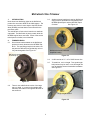
Service Manual
32cc String Trimmer
Power Head
NOTE: These materials are for use by trained technicians who are experienced in the service and repair of outdoor power
equipment of the kind described in this publication, and are not intended for use by untrained or inexperienced individuals.
These materials are intended to provide supplemental information to assist the trained technician. Untrained or inexperienced
individuals should seek the assistance of an experienced and trained professional. Read, understand, and follow all instructions
and common
sense when working
on power
equipment.
This includes
the contents of the product’s
Operators Manual, supplied
IMPORTANT:
READ
SAFETY
RULES
AND INSTRUCTIONS
CAREFULLY
with the equipment. No liability can be accepted for any inaccuracies or omission in this publication, although care has been
This itService
Manual
not a substitute
Manual.However,
You must
taken to make
as complete
andisaccurate
as possiblefor
atthe
the Operator’s
time of publication.
dueread,
to theunderstand
variety of outdoor power
equipmentand
andfollow
continuing
changesin
that
occur
over time,
updates
be made toManual
these instructions
from time to time.
all ofproduct
the directions
this
manual
as well
as thewill
Operator’s
before working
Therefore,on
it may
be
necessary
to
obtain
the
latest
materials
before
servicing
or
repairing
a
product.
The
company
reserves the
this power equipment.
right to make changes at any time to this publication without prior notice and without incurring an obligation to make such
changes to previously published versions. Instructions, photographs and illustrations used in this publication are for reference
use only and may not depict actual model and component parts. © Copyright 2005 MTD Products Inc. All Rights Reserved
MCCULLOCH CORPORATION P.O. BOX 31567, TUCSON, AZ 85751-1567
MTD Products LLC - Product Training and Education Department
PRINTED IN USA
FORM NO. 769-00942
(10/2003)
McCulloch 32cc Trimmer
1.
INTRODUCTION
2.3.
North American distribution rights to the McCulloch
product line are new to MTD for the 2004 season. The
trimmers are similar in some ways to the MTD SouthWest (RYOBI) products that we have offered for the
past three years.
Another trimmer head that is used on McCulloch
string trimmers resembles a cross between the
MTDSW Speed Spool and the MTDSW Tap-NGo head.
See Figure 2.3.
The architecture of both units is based on a cantilever
crankshaft. The McCulloch is piston ported, while the
MTDSW engine has a reed valve. Some of the service
techniques are similar, but not identical.
2.
TRIMMER HEADS
2.1.
One trimmer head available on the McCulloch
products is nearly identical to the MTDSW TapN-Go. The operating principle is the same, but
the parts are different enough that they are not
fully interchangeable. See Figure 2.1.
McCulloch trimmer head with
simplified loading
McCulloch version
of small tap-n-go
Figure 2.3
2.4.
A refill consists of 15’ - 20’ of .080” trimmer line.
2.5.
To install line, cut it to length. Two equal-length
half-portions may be used, or one full length line
may be installed, then trimmed after installation.
See Figure 2.5.
Figure 2.1
2.2.
There is also a McCulloch version of the large
tap-n-go head. It is used on the straight shaft
trimmers, and rotates in the opposite direction of
the small one.
Single-length method
Figure 2.5
1
McCulloch 32cc Trimmer
2.6.
2.8.
Align the arrows on the spool with the arrows on
the housing. See Figure 2.6.
From the eyelet, the line will be channeled up
under the bump knob by a set of ramps in the
spool. See Figure 2.8.
Housing
Spool
Ramps
Arrows
(marked for
clarity)
Bump knob
removed for
clarity
Anchors
Bump knob
Figure 2.6
Figure 2.8
2.7.
Insert a length of trimmer line through each eyelet. There are two sheaves for line in the spool,
separated by a narrow groove. The line must
enter the narrow groove. See Figure 2.7.
2.9.
The ends of the line are looped-through the
anchors to hold them in place, then pulled-tight.
NOTE: With the arrows aligned, the line can also
be installed from the inside-out, by removing the
bump knob.
Eyelet
2.10. The final step is to rotate the spool in the direction indicated by the arrows, drawing the line into
the head. See Figure 2.10.
Inset: arrow on spool, marked
for clarity
Center
groove
Figure 2.7
Figure 2.10
2.11. Stop winding when each end of the line is about
6” long.
2.12. Press the bump knob and pull on the line to
manually test the trimmer head. Do not push the
housing off it’s seat while testing.
2
McCulloch 32cc Trimmer
2.13. If repair is required, remove the bump knob, and
withdraw the spool. See Figure 2.13.
2.17. The ratchet wedges can be serviced by removing the three screws holding the black cover to
the top of the housing. See Figure 2.17.
Ratchet wedges
Small springs behind
Spring
Holes for screws
Ribs
Tabs
Cover
Figure 2.13
Figure 2.17
2.14. Check for: tangled line, damaged tabs on the
spool, worn ribs on the spool, missing spring,
broken ratchet wedges.
2.18. Carefully remove the springs, and pull out the
wedges. See Figure 2.18.
2.15. Replace the spool if it is worn or damaged.
NOTE: Bump knobs are a wearable item, and
are replaced in the course of normal use.
2.16. The housing is not fastened to the boom. It simply rests over a hexagonal drive collar.
See Figure 2.16.
Spring seats over
post on back of wedge
One rounded side,
insures correct orientation
Drive collar
Figure 2.18
Figure 2.16
3
McCulloch 32cc Trimmer
3.3.
2.19. When properly installed, the wedges should be
spring loaded. They retract when the ribs on the
back of the spool pass them, then extend to
keep the spool from rotating backwards.
See Figure 2.19.
To separate the powerhead from the boom,
remove the screw at the top of the grip using a T25 driver, then withdraw the boom.
See Figure 3.3.
Trigger housing and
grip slip off of boom
Spring loaded
ratchet wedges
Screw
removed
Figure 3.3
Figure 2.19
3.4.
3.
RECOIL STARTER
3.1.
Next to the cutting head, this is probably the
most common service item on the trimmer. It is
similar in principle to the MTDSW starter, but the
routing of the throttle and stop switch cables
necessitates a slightly different approach.
3.2.
The throttle trigger, stop switch, and grip can all
be removed from the boom in unit with the
power-head. See Figure 3.2.
Remove the air filter cover using a T-25 driver to
gain access to the connection between the throttle cable and the throttle arm on the carburetor.
See Figure 3.4.
Air filter
cover
Screw holds grip
and Throttle housing
to boom
Figure 3.4
Positioning mark
Figure 3.2
4
McCulloch 32cc Trimmer
3.5.
Disconnect the throttle cable from the carburetor
by unhooking the Z-fitting at the carburetor end
of the cable. See Figure 3.5.
3.7.
Remove the two screws from the trigger housing
cover using a T-15 driver. See Figure 3.7.
Stop switch
Throttle arm
on carburetor
Trigger housing
cover screws
Trigger housing
Z-fitting on end of
throttle cable
Trigger housing cover
Figure 3.7
Figure 3.5
3.8.
3.6.
After the powerhead is separated from the
boom, and the throttle cable is slackened, the
housing that contains the stop switch and throttle
trigger can be separated from the grip.
Push the front part of the housing forward to
remove it. See Figure 3.8.
Grip
Trigger housing
slips out of grip
NOTE: Alternatively, instead of removing the
complete powerhead and grip from the boom,
the clutch housing can be separated from the
starter housing. If this approach is taken, the
stop switch wires must be disconnected as the
two sections are separated. The throttle cable
will pull out of the starter housing and clutch
housing as the powerhead is removed. Because
of the difficulty of routing the throttle cable back
through the housings, a wire or string should be
connected to the z-fitting so that the throttle
cable can be “fished” back into place.
Stop switch
contacts
Stop switch mounted
on cover plate
Figure 3.8
3.9.
The throttle trigger will be released from its pivot
point, and the stop switch will remain with the
rear portion of the housing.
NOTE: The stop switch contacts two rub strips to
ground-out the ignition module. One rub strip is
connected to the primary windings of the module, the other leads to ground.
5
McCulloch 32cc Trimmer
3.12. The grip and clutch housing can be separated
from the engine by removing the four screws
that fasten them together, using a T-25 driver.
See Figure 3.12.
3.10. The trigger housing can be pulled-free of the grip
after the trigger and rear housing are removed.
See Figure 3.10.
Channel for
throttle cable
Channel for
stop switch wires
Stop switch wires
Clutch housing
Starter
housing
White plastic
sleeve
NOTE:The grip is
integral with the
clutch housing
Figure 3.10
Figure 3.12
NOTE: The throttle cable and stop switch wires
are held in adjacent channels by a white plastic
sleeve that is inserted in the grip.
3.13. Remove the grip and clutch housing, and unplug
the stop switch wires from their connections on
the engine. See Figure 3.13.
3.11. Pull the white sleeve out of the grip and unplug
the stop switch wires from their connections to
the contact strips in the trigger housing.
See Figure 3.11.
Channel for stop
switch wires
Channel for
throttle cable
Remove
sleeve
Figure 3.13
NOTE: Pay attention to the routing of the throttle
cable and stop switch wires.
Figure 3.11
3.14. Disconnect the H.T. lead from the spark plug.
and remove the spark plug using an 5/8”
wrench.
3.15. Pack the cylinder full of starter rope to act as a
piston stop.
6
McCulloch 32cc Trimmer
3.16. Remove the clutch drum using a T-25 driver.
See Figure 3.16.
3.18. The flat side of the clutch rotor seats against a
tube that surrounds the crankshaft.
See Figure 3.18.
Recoil rope used
as a piston stop
Flat side of clutch rotor
faces starter housing
Tube
Clutch drum
Figure 3.16
Figure 3.18
3.17. After the clutch drum is removed, the clutch rotor
can be removed using MTDSW clutch removal
tool # 791-180919. See Figure 3.17.
3.19. With the clutch rotor removed, the starter housing can be removed.
3.20. Take out the four screws holding the starter
housing to the engine using a T-25 driver.
See Figure 3.20.
Throttle cable
Crankshaft
Clutch rotor
Starter housing
Spade terminals
for stop switch wires
Screws
Figure 3.17
NOTE: a hammer and soft drift can be used if
the MTDSW tool is unavailable.
Figure 3.20
7
McCulloch 32cc Trimmer
3.23. Alternatively, the throttle cable could be disconnected from the engine by squeezing the tabs,
and removing it along with the starter housing.
See Figure 3.23.
3.21. Unplug the stop switch wires from the ignition
module as the starter housing is removed from
the engine. See Figure 3.21.
Stop switch wires
Squeeze tabs
Starter housing
Ignition module
Figure 3.21
Figure 3.23
NOTE: There are two sets of stop switch wires.
The set inside the starter housing connects to
the ignition module. The set of stop switch wires
in the clutch housing connects the set inside the
starter housing to the stop switch.
NOTE: If a throttle cable needs replacement,
attach a line to the carburetor end of the old
cable before removal, to facilitate “fishing” the
replacement cable into place.
3.24. Remove the baffle from the starter housing using
a T-25 driver.
3.22. The throttle cable is best left in the starter housing as it is removed. This can be done by simply
rotating the starter housing out of the way.
See Figure 3.22.
NOTE: The starter pulley is held in place by the
baffle. There are no other fasteners on it.
Starter housing removed
3.25. Once the baffle is removed, the starter pulley
can be carefully lifted out to access the recoil
spring. See Figure 3.25.
Stop
switch
wires
Posts
Throttle cable
Figure 3.22
Baffle
Figure 3.25
8
McCulloch 32cc Trimmer
3.30. As the starter is reassembled, apply a sparing
amount of white lithium grease to the friction surfaces of the starter pulley.
NOTE: If the starter rope is not broken, it will be
necessary to relieve tension from it before
removing the starter pulley.
3.31. Pay close attention to the routing of the stop
switch wires.
3.26. Examine the pulley and spring for wear and
damage. Look for straightened ends on the
spring. Look for rounded edges on the teeth of
the starter pulley. See Figure 3.26.
Starter pulley
3.32. Wind tension onto the starter rope after the pulley is in place, but before the baffle is installed.
It will be necessary to use caution nut to pull
upward on the rope, dislodging the pulley from
the spring. Light thumb pressure on top of the
pulley is advised. See Figure 3.32.
Spring cover
Spring ends
Figure 3.26
3.27. When installing new starter rope, use about 6’ of
3/16 starter rope.
Figure 3.32
3.28. After the starter pulley is removed, the starter
spring can be lifted out of the starter housing,
complete with the steel cartridge that contains it.
See Figure 3.28.
3.33. If the starter pawls on the flywheel are worn or
damaged, remove the flywheel. See Figure 3.33.
Spacer
Tube
Nut
Flywheel
Starter
spring in
cartridge
Notches engage
end of spring
Starter pawls
Plastic shield
Figure 3.33
Figure 3.28
NOTE: In particular, look for rounded edges on
the corners of the pawls that engage the teeth
on the pulley.
3.29. There is a plastic shield that fits between the
starter pulley and the starter spring.
9
McCulloch 32cc Trimmer
3.39. If the pawls are damaged, they are available as
a pair, with mounting hardware, in kit form.
See Figure 3.39.
3.34. Remove the spacer and tube from the crankshaft.
3.35. Remove the nut from the crankshaft using a
deep 11/16” socket. See Figure 3.35.
Starter pawl
Tube
Damaged edge
Spacer
Crankshaft
Nut
Figure 3.39
Figure 3.35
3.40. Release the retainers on the back side of the flywheel to remove the starter pawls.
See Figure 3.40.
3.36. Pry up on one thick section of the flywheel, and
strike the opposite side with a soft dead-blow
hammer. See Figure 3.36.
Pawl retainers
Threads for
clutch rotor
Threads
for nut
Key
Tapered seat
Figure 3.40
Figure 3.36
3.41. After replacing the pawls or the flywheel, carefully seat the key and flywheel back on the
crankshaft.
3.37. Lift the flywheel off of the crankshaft, using caution not to lose the flywheel key.
3.42. Install the nut, and torque it to xx in-lbs., then
place the spacer and tube back over the crankshaft.
3.38. If the flywheel has any chips, cracks, or broken
vanes, discard it. Re-using a damaged flywheel
presents a burst hazard.
10
McCulloch 32cc Trimmer
3.43. Removing the starter housing will also allow
access to the ignition module. If the ignition
module is removed for any reason, the air-gap
must be adjusted with the flywheel securely fastened. See Figure 3.43.
3.46. As the starter housing goes-on, connect the
short lengths of stop switch wire that are inside
the starter housing to the ignition module, and
clip the throttle cable into the hole in the engine
case. See Figure 3.46.
Check air gap
Throttle cable
Male spade terminals
for stop switch wires
Figure 3.43
Figure 3.46
3.44. Set the air gap to .014” using a non-magnetic
feeler gauge.
3.47. Secure the starter housing to the engine.
3.48. Install the clutch rotor and drum.
See Figure 3.48.
3.45. After the starter is assembled, carefully position
the starter housing, throttle cable, and stop
switch wires, and install the starter housing to
the engine. See Figure 3.45.
Stop switch wires
Throttle
cable
Figure 3.48
Figure 3.45
11
McCulloch 32cc Trimmer
4.
3.49. Connect the stop switch wires in the clutch housing to the male spade terminals on the ends of
the stop switch wires in the starter housing, and
position the throttle cable as the clutch housing
is lowered into place. See Figure 3.49.
EXHAUST
If the fuel/oil mixture is too rich, the exhaust port and
muffler may accumulate deposits of carbon. These
deposits will hinder high-R.P.M. engine performance
and increase operating temperatures. Eventually, they
may lead to a no-start situation. There is a characteristic “flat” tone to the exhaust noise that accompanies a
blocked exhaust.
4.1.
The engine cover must be removed to gain
access to the muffler. See Figure 4.1.
Air filter cover
Engine cover
Engine
cover
screw
Figure 3.49
D-shaped
washer
NOTE: The wires and cable should be positioned as they were in Figure 3.13.
3.50. Secure the clutch housing to the starter housing.
Figure 4.1
3.51. Position the throttle cable and stop switch wires
as they were in Figure 3.11.
3.52. Insert the white plastic sleeve into the grip.
3.53. Connect the carburetor end of the throttle cable,
then assemble the throttle trigger housing.
4.2.
Disconnect the high tension lead form the spark
plug.
4.3.
Remove the air filter cover using a T-25 driver.
See Figure 4.3.
3.54. Install the power-head on the boom.
Engine
cover
screw
Air filter
Figure 4.3
4.4.
12
This will allow access to the screw that secures
the carburetor side of the engine cover.
McCulloch 32cc Trimmer
4.5.
Remove the three screws that secure the engine
cover, using a T-25 driver. See Figure 4.5.
4.8.
The muffler can be easily removed by unhooking
the spring and bale that retain it. See Figure 4.8.
Round
washer
Hook on
cylinder
Bale
Screw
Spring
Figure 4.5
Figure 4.8
NOTE: the screw on the exhaust side of the
engine has a plastic washer. The screw on the
back side of the engine has a round steel
washer. The screw on the carburetor side of the
engine cover has no washer.
4.6.
4.9.
With the engine cover removed, the spark arrestor and muffler are accessible. See Figure 4.6.
Rotate the bale upward to liberate the muffler,
muffler gasket, and port gasket.
See Figure 4.9.
piston skirt
Muffler
Exhaust port
Spark arrestor
Figure 4.9
NOTE: The exhaust port provides an ideal window into the cylinder to inspect the condition of
the piston skirt and the cylinder wall.
Figure 4.6
4.7.
4.10. Bale fits just beneath the largest cooling fin on
the cylinder, and hooks into the cylinder. Rotate
it to unhook it.
The spark arrestor is easily removed for cleaning
or replacement using a phillips head screwdriver, or a nut driver.
4.11. Clean the muffler and port if necessary, using
care not to damage the piston or knock carbon
into the cylinder.
NOTE: The spark arrestor consists of a screen,
a cover, and a screw. It is available as a kit.
13
McCulloch 32cc Trimmer
5.
4.12. Install the muffler using a new gasket.
See Figure 4.12.
FUEL SYSTEM
Carburetor repair is beyond the scope of this manual,
but service information is available from Walbro and
Zama, the manufacturers whose carburetors are used
on McCulloch products.
5.1.
The fuel filler cap contains a polymer “stone”
tank vent. If it becomes blocked, the tank may
pressurize when heat-soaked, flooding the
engine.
5.2.
The opposite situation may occur if the engine is
run with a blocked tank vent. Air will be unable
to enter the tank to replace the fuel that is consumed by the engine. This will create a vacuum,
and fuel starvation will occur. See Figure 5.2.
exhaust gasket
Figure 4.12
4.13. Install the engine and air filter covers, and connect the high tension lead to the spark plug.
4.14. Test run the unit before returning it to service.
NOTE: The engine can be test-run briefly with
the muffler removed. Hearing protection is
strongly suggested. Extended running (30 seconds or more) is not recommended without the
engine cover and muffler in place.
Fuel cap vent
Wet-bulb
primer
Figure 5.2
5.3.
The air filter cover is easily removed using aT-25
driver. See Figure 5.3.
Figure 5.3
14
McCulloch 32cc Trimmer
16