1
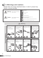
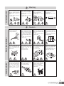
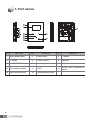
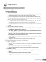
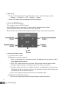
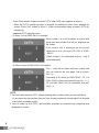
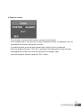
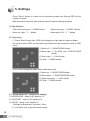
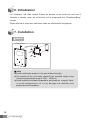
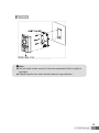
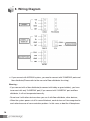
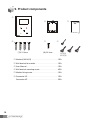
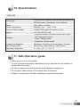
User Manual
Color Video Door Phone CMV-43S
�
• Thank
Thank you
you for
for purchasing
purchasing COMMAX
COMMAX products.
products.
�
• Please
Please carefully
carefully read
read this
this User’s
User’s Guide
Guide (in
(in particular,
particular, precautions
precautionsfor
forsafety)
safety)before
beforeusing
usingaaproduct
productand
andfollow
follow
instructions
instructions to
to use
use aa product
product exactly.
exactly.
�
• The
The company
company isis not
not responsible
responsible for
for any
any safety
safety accidents
accidents caused
caused by
byabnormal
abnormaloperation
operationof
ofthe
theproduct.
product.
Table of Contents
1. Greetings ...............................................................................................1
2. Warnings and Cautions...........................................................................2
3. Part names..............................................................................................4
4. Operation ................................................................................................5
5. Settings .................................................................................................10
6. Initialization ...........................................................................................12
7. Installation .............................................................................................12
8. Wiring Diagram. ....................................................................................14
9. Product components .............................................................................16
10. Specifications ......................................................................................17
11. Safe Operation guide ..........................................................................17
1. Greetings
● Thank you for Purchasing COMMAX Products
● Please
carefully read this User's Manual (in particular, precautions for safety) before using a
product and follow instructions to use a product exactly.
1
2. Warnings and cautions
Please follow the things described below in order to prevent any
danger or property damage.
Warning
Prohibition.
It may cause a serious damage or
injury if violated.
No disassembly
No touch
Caution
Must follow strictly.
Shows plugging out the power cord
without an exception
It may cause a minor damage or
injury if violated.
Shows the warning and caution for an electric shock.
Shows the warning and caution for a fire.
Power & Installation
Warning
2
Please don’t use several
products at the same time on
one power socket.
·It may cause a fire due to an
abnormal overheating.
Please don’t bend the power
cable excessively or it may
cause an electric shock.
·fire when using a damaged
power cable.
Please don’t handle the
power cable with a wet hand.
·It may cause an electric
shock.
Please plug out the power
cable from the socket when
not using it for a long period
of time.
·It may shorten the product
lifespan or cause a fire.
Please don’t install the
product in the place where
there is much oil, smoke or
humidity.
·It may cause an electric
shock or fire.
Please don’t install the
product with the lightening
and thunder.
·It may cause an electric
shock or fire.
Please don’t use and connect
this product with other
products with different rated
voltage
·It may cause a disorder or
fire.
When installing the product
that generates heat, please
install the product away from
the wall (10cm) for the
ventilation.
·It may cause a fire due to
the increased internal
temperature.
Cleaning & Use
Warning
Please don’t disassemble,
repair or rebuild this product
arbitrarily (please contact the
service center if a repair is
needed.
·It may cause an electric
shock or fire.
If an abnormal sound, burning
smell or smoke is coming out
of the product, please plug out
the power cable and contact a
service center.
·It may cause an electric
shock or fire.
Please don’t insert any
metallic or burnable materials
into the ventilation hole.
·It may cause an electric
shock or fire.
Please use only the designated
batteries for the products of
using DC power.
·It may cause an electric
shock or fire.
Cleaning & Use
Power & Installation
Caution
Please plug the power cable
firmly into the inner end
·It may cause a fire.
Please hold the plug tightly
when unplugging the power
cable (a part of the copper
wire may be disconnected if
the grabbing is only made on
the cord when pulling out the
cable).
·It may cause an electric
shock or fire
When connecting the power
cables after cutting the cable,
please install the product with
power off
·It may cause an electric
shock or fire
Please be careful when using
an AC circuit breaker since
there is a possibility of an
electric shock.
Please check the use voltage
and current for the DC-only
products and use the
appropriate rectifier.
·It may cause a fire.
Please avoid direct rays of the
sun or heating devices at a
time of installation.
·It may cause a fire.
When cleaning the product,
please rub it with a soft and
dry cloth after plugging out
the power cable. (Please
don’t use any chemical
products such as wax,
benzene, alcohol or cleanser.)
Please don’t drop the
product on the ground and
don’t apply a shock .
·It may cause a failure.
Please use the designated
connection cable within the
maximum calling distance
designated for the product
·It may reduce the product
performance.
When installing the product,
please fix it firmly while using
the wall-mounting unit and
screws.
·It may cause an injury from
the falling object.
Please don’t install the
product on an unstable place
or small support board.
·It may cause an injury if it
falls down while in use.
3
3. Part names
No.
Part name
No.
Part name
No.
Part name
1
Menu button(side)
2
Enter button
3
△ button
4
▽ button
5
Power ON/OFF
6
Speaker
7
4.3” TFT LCD
8
Monitoring button
9
Talk button
10 Door release button
11
C-MIC
12
Guard and interphone
button
13 Menu button(touch)
14
Connecting terminals
4
4. Operation
4-1 Functions for single & MODUM system
4-1-1 Use for single system
1) Communicate with visitor
(1) Communicate in Monitor
① As the paging button on a door camera is pressed, the paging tone rings at the
connected videophone and the visitor’s figure appears on the monitor.
② Press “Call” button to talk to the visitor and “Door release” button to open the door.
(The door release function is enabled only when the screen is turned on and the
individual door camera has door release terminal)
③ If another visitor calls from another entrance during a call, the first call is
automatically ended and the connection to another entrance is made.
④ Press the “Call” button to finish the communication and convert to the standby
mode.
(2) Communicate with additional interphone
① As the paging button on a door camera is pressed, the paging tone rings at the
interphone and videophone at the same time.
② Pick up the hand-set to start talking with a visitor, and to release the door for
pressing HOOK switch or Door release button.
(The door release function is enabled only when the screen is turned on and the
individual door camera has door release terminal).
③ Visitor, interphone and monitor can communicate at the same time if press the “Call”
button of monitor.
④ Hang off the hand-set to finish the call and convert to standby mode.
2) Communication between the monitor and interphone
(1) Monitor ➔ Interphone
① Press the “Guard and interphone” button in the monitor, the paging tone rings at the
interphone.
② Pick up the handset to start communicating with interphone.
③ Press “Call” button to finish the communication and convert to standby mode.
(2) Interphone ➔ Monitor
① Pick up the hand-set and press the “Call” button, the paging tone rings at the
monitor.
② Press “Call” button on the monitor to start communicating.
③ Hang off the hand-set to finish the communication and convert to standby mode.
5
3) Monitoring
① Press the “Monitoring button” in standby mode, you can check the image in order.
- Camera 1 → Camera 2 → OFF → Camera 1 → repeat
② Press “Call” button during monitoring to call to the entrance.
4-1-2 Use for MODUM system
- This function is only for MODUM system.
- If the MODUM system is connected, it is automatically recognized when it boot.
Please reboot the power after installation for stable operation.
- Enter the OSD menu, OSD will be arranged in order as same as front touch key buttons
1) Communicate with visitor
(1) Communicate in monitor
(a) Paging from a common entrance
① When a visitor page from a common entrance, the paging tone rings and the visitor’s
figure appears on the monitor.
② Press “Call” button to talk to the visitor and “Door release” button to open the door.
(The door release function is enabled only when the screen is turned on.)
③ If another visitors calls from an individual entrance, the paging tone rings and press
“Monitoring” button to receive a call from the individual entrance after finishing the
communication with a common entrance.
④ Press “Call” button to finish the call and convert to standby mode.
(b) Paging from an individual entrance
- Same as the Single system mode.(Except interphone related information)
6
- The paging tone rings when it is received a paging from a common entrance or guard
station while talking with the individual entrance. Press “Guard and interphone” button to
connect after finishing communication with the individual door unit.
2) Communication with a guard
(1) Receive a call
① The paging tone rings when receive a call from guard station.
② Press “Call” button to communicate.
③ When it receive any paging from an individual door camera, the paging tone rings and
press “Monitoring” button to receive a call from the individual door camera after
finishing the communication with a guard station.
④ Press “Call” button to finish the communication and convert to standby mode.
(2) Make a call
- The following menu appears on the right-lower corner when “Guard and interphone”
button is pressed in standby mode.
- For paging “Porter”, press “Monitoring” button
while the menu is displayed on the screen.
: The call is connected if PORTER receives it.
- For paging “Guard”, press “Guard and
interphone” button while the menu is displayed
on the screen.
: The call is connected if the guard receives it.
- Press “Call” button if you don’t make a call.
3) Monitoring (Individual entrance / Common entrance / CCTV)
- The following menu will be appeared on the right-lower corner when press the “Monitoring”
button in standby mode.
- Press “Monitoring” button to monitor the
individual entrance when OSD menu displays
on screen.
- Press “Guard and interphone” button to monitor
the common entrance when OSD menu
appears on screen.
: Press “Call” button to make a call while
monitoring the individual and common entrance.
Press “Call” button to finish the menu.
7
- Press “Door release” button to monitor CCTV when OSD menu appears on screen.
: When the CCTV monitoring mode is selected, the additional select menu displays on
screen. Press “Call” button to finish it. (Refer to description below to select CCTV for
monitoring.)
- Additional CCTV selection menu
(1) When 1 unit of CMD-104VU is installed,
: Ports number 1 to 4 will be shown on screen and
press each port number that will be displayed on
the screen.
: Port number that is displayed on the screen
depends on the setting of DIP S/W of CMD104VU.
(If port number 1-2 is connected, only no. 1 and 2
will be displayed)
(2) When 2 units of CMD-104VU are installed
: The ▷ mark will be shown with port number and
you can move on the next page. (Up to 8 ports,
No. 1-8)
: According to ID setting of CMD-104VU, ID 1 of
CMV-104VU will be connected with port No. 1 ~ 4,
ID 2 of CMV-104VU will be connected with port
No.5 ~ 8.
NOTE
1. You can check the other CCTV screen pressing other numbers while you are monitoring.
(If you press the same button that you have already monitored, monitoring will be finished
and convert to standby mode.)
2. You can select up to 8 CCTV, and available quantities are automatically recognized and
displayed on screen.
8
4) Page the elevator
- If the elevator is connected with monitor, you can use this function.
- In the standby mode, if you press the “Guard & Interphone” button, the additional menu will
be displayed at the lower-right corner of screen.
- For paging elevator, press the door release button while the menu is displayed.
- When you page the elevator, “EVL CALL” message will be displayed at the top of screen.
- After paging the elevator, the screen will be back to the standby mode.
- If you don’t page the elevator, press the “CALL” button.
9
5. Settings
- Press “Menu” button in video call or monitoring mode then Setting OSD will be
shown on screen.
- Both front touch keys and side switches can be used for settings as below.
1) Side switches
- Start and finish menu : ① MENU button
- Move up / right : ③ △ button
- Select and input : ② SELECT button
- Move down / left : ④ ▽ button
2) Touch keys
- ⑬ Press “Menu" button then OSD will be display on right side of screen as below.
- As same as menu OSD, the front touch key buttons will be arrayed as same as OSD
menu.
(1) Move left : ⑧ MONITORING button
(2) Move right : ⑫ GUARD and INTERPHONE
button
(3) Start menu : ⑨ CALL button
(4) Finish : ⑬ MENU button
- OSD will be changed as below when select any menu.
(1) Move up : ⑧ MONITORING button
(2) Move down : ⑩ DOOR RELEASE button
(3) Select and enter : ⑨ CALL button
(4) Finish : ⑬ MENU button
5-1 DOOR VIDEO SET (Control the display)
1) BRIGHTNESS : select 0~20, defaults 10
2) CONTRAST : select 0~20, defaults 10
3) COLOR : select 0~20, defaults 10
- Settings for Brightness / Contrast / Color
(1) Use “Move” key to go to the each section
10
(2) Press “Select” key to activate the section(Move to the select window)
(3) Use “Move” key to adjust the level from 0 to 20.
(4) After adjustment, press “Select” key to go back to menu.
4) RESET : Reset Brightness / Contrast / Color.
Press “Select” key and select YES. And then press “Select” key again to reset.
5) EXIT : Press “Select” key to go back to setting menu
5-2 UTILITY(Set the volume and screen ratio)
1) CHIME-BELL VOLUME : Adjust the chime-bell volume when it receives the paging.
- Adjust from 0(MUTE) to 3(MAX).
2) SPEAKER VOLUME : Adjust the speaker volume while calling.
- Adjust from 1(MIN) to 3(MAX).
3) CHIME-RECALL MODE : Sets the count of chime-bell.
- SINGLE : 1 time / REPEAT : Continually
4) EXIT : Press “Select” key to go back to setting menu.
5-3 INFORMATION (Check product name and version)
1) Model : Product name
2) Version : Product version
3) HOME ID : Display the household number.
4) Video : Display the transmission formats (PAL / NTSC)
5) Source : Display the position of camera (lobby, entrance camera etc.)
6) Touch : Display the touch key version.
5-4 EXIT
- Using the move buttons to “Exit” menu and finish the setting.
11
6. Initialization
- As “Interphone” and “Door release” buttons are pressed, at the same time, more than 3
seconds in standby mode, the initialization will be progressed with “Beep-Beep-Beep”
sounds.
- Please note that all information and screen mode are initialized with this progress.
7. Installation
▷ Monitor
SCREW M3(1EA)
※ Note
SCREW T4(4EA)
● Avoid installing the product in the area of direct sunlight.
● The position of the unit's body should fit the standard height range
(Recommended height range is 1450 ~ 1500mm.)
● Avoid installing the product exposed to gas exposure, magnetic force,
in humid temperatures, as it may damage the condition and
performance of the product.
12
▷ Camera
※ Note
● Do not install a door camera in the area exposed to direct sunlight or
backlight.
● Please keep the lens clean for the clearest image reflection.
13
8. Wiring Diagram
※ If you connect with MODUM system, you need to connect with 'CAMERA2' ports and
floor distributor(Please refer to the manual of floor distributor for wiring.)
Warning :
- If you connect with a floor distributor(to connect with lobby or guard station), you have
to connect with only 'CAMERA2' port.(If you connect with 'CAMERA1' port and floor
distributor, it will not be operated normally.
- Do not use it with other devices when you use it with floor distributor, other devices,
- When the system power cut off in case of blackout, each device can't be recognized to
each other because of communication problem. In this case, re-boot the Video-phone.
14
※ Note
1. In case, if there is a high-voltage power line in the area of installation, use metal tube
coaxial cable for wiring
2. Beware of wrinkling of line coating and cable stick-outs as it may cause circuit shortage
and operation inconvenience.
3. When connecting a monitor with a camera, make sure power switch is turned off.
15
9. Product components
①
②
④
⑤
(T)4 X 18mm
(M)3 X 6mm
③
⑥
2P(1EA)
4P(3EA)
① Monitor(CMV-43S) . . . . . . . . . . . . . . . . . . . . . . . . . .1EA
② Wall bracket for monitor . . . . . . . . . . . . . . . . . . . . . .1EA
③ User Manual . . . . . . . . . . . . . . . . . . . . . . . . . . . . . . .1EA
④ Wall bracket mounting screw . . . . . . . . . . . . . . . . . .4EA
⑤ Monitor fixing screw . . . . . . . . . . . . . . . . . . . . . . . . . .1EA
⑥ Connector 2P . . . . . . . . . . . . . . . . . . . . . . . . . . . . . .1EA
Connector 4P . . . . . . . . . . . . . . . . . . . . . . . . . . . . . .3EA
16
10. Specifications
CMV-43S
Wiring type
Power
Power Consumption
Communication method
Monitor
Camera 4-wire (Polarity, CAM2 will be convertible with
MODUM system) Inperphone 4-wire (Polarity)
100V-240V~, 50/60Hz
Stand by : 4 W
Max : 10 W
HANDS FREE type (Voice switch circuit)
4.3″ TFT-DIGITAL LCD
- Individual entrance: Electronic chime with 3 tones
(for 2 consecutive times)
Ringtone
- Guard : Melody chime
Image transmitting time
Max. Distance(UTP)
Operating Temperature
- Interphone : Electronic bell
Monitoring : 30 ±5sec , Communication : 60 ±5sec
28m(0.5mm) / 50m(0.65mm) / 70m(0.8mm)
0 ~ +40℃ (32°F ~ 104°F)
11. Safe Operation guide
●
●
●
●
●
Make sure to turn on the product
In case if physical damage or operation failure is detected, do not hesitate to
contact Service Center
All electric power must be blocked by the building blocking device
Do not place water bottles or flowerpots upon the product
Please, turn the power off when installing or repairing the product
17
513-11, Sangdaewon-dong, Jungwon-gu, Seongnam-si, Gyeonggi-do, Korea
Int’l Business Dept. Tel. : +82-31-7393-540~550 Fax. : +82-31-745-2133
Web site : www.commax.com
PM5443S00010
Printed In Korea / 2015.03.104


![У]о:(mЧєь{Сr˙„~®M −Ї‹ОЄ* hˇОˆt](http://vs1.manualzilla.com/store/data/006000975_1-aa867c7069e2492e9edc151c99229eb0-150x150.png)