1
INSTRUCTIONS
REV. 2-2-04
-J01793
®
Kit Number 67922-98D
FLTR/I NACELLE (LH) REPLACEMENT KIT
General
i01831
Top
This left side nacelle kit can be installed on 1998 and later
FLTR/I Model Motorcycles.
Kit Contents
Qty
1
1
1
1
Description
Nacelle (LH)
Clip
Plug (clutch cable hole)
Plug (reset hole)
Bottom
Part Number
67922-04
70385-01
789
728
1
1
NOTES
1998-1999: Locate the odometer reset switch in either the
left nacelle switch panel or the front hole in the right nacelle.
Plug (Part No. 728) is used to plug the unused hole. Plug
(Part No. 789) is used to plug the clutch cable clip hole. For
installation instructions, see page 2.
2000-2002: Locate the odometer reset switch in either the
left nacelle switch panel or the front hole in the right nacelle.
Plug (Part No. 728) is used to fill the empty hole. The clutch
cable clip (Part No. 70385-01) can be used to capture the
clutch cable or the plug (Part No. 789) fills the clip hole. For
installation instructions, see page 4.
2001-2002 FLTRSE models will require a Service Manual
for clutch cable routing instructions.
2003: The odometer reset switch is located in the left
nacelle switch panel. The clutch cable can be captured in
the clip (Part No. 70385-01) or the plug (Part No. 789) fills
the clip hole. For installation instructions, see page 6.
2
3
4
6
5
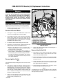
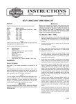
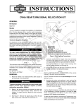
1. Release button
2. Knob
3. Nut
4. Collar
5. Spacer
6. Tab (down and forward)
Figure 2. Ignition Switch
(all models)
i06199
2004: The odometer reset switch is located in the left front
switch panel and the clip is used to capture the clutch cable.
No plugs are used. For installation instructions, see page 8.
1
2
i05042
4
40
30
20
10
0
H
AR
LE
50 60 70
Y -D
MPH
80
90
100
110
120
Y
N
PA
M
CERTIFIED
CO
AVI
DSON MOTOR
30
40
50
60
20
70
10
RPMx100
0
H
AR
LE
Y -D
AVI
DSON MOTOR
80
Y
N
PA
M
CO
3
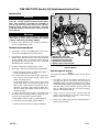
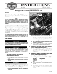
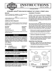
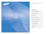
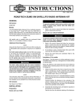
1. Clutch cable clip hole
2. Instrument bezel mounting hole
3. Speaker switch connector [105B]
4. Switch bracket
Figure 1. Instrument Bezel Screws
(all models)
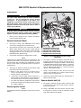
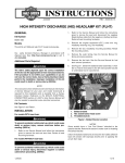
Figure 3.Kit Nacelle (LH) (Part No. 67922-98D)
(with switch bracket and wiring)
1 of 9
1998-1999 FLTR/I Nacelle (LH) Replacement Instructions
Installation
i05043
1WARNING
1
4
The rider’s safety depends upon the correct installation
of this kit. Use the apropriate service manual procedures. If the procedure is not within your capabilities or
you do not have the correct tools, have a HarleyDavidson dealer perform the installation. Improper
installation of this kit could result in death or serious
injury. (00333a)
3
2
1WARNING
To prevent accidental vehicle start-up, which could
cause death or serious injury, disconnect the negative
(-) battery cable before proceeding. (00048a)
1.
Remove seat to provide access to battery and disconnect the negative battery cable.
5
Remove Instrument Bezel
2.
See Figure 1. Using a T25 TORX drive head, remove
screw on left and right side of instrument bezel.
3.
Use thumbs to push tab at rear of bezel from slot above
ignition switch. Gently raise free side of bezel until tabs
on left and right sides of instrument nacelle become
disengaged from slot at top of bezel (slot is concealed
behind decorative adhesive strip).
4.
Lift bezel and instrument wiring from the nacelle.
5.
See Figure 2. Disconnect the mechanical speedometer.
a. Rotate knurled nut at back of speedometer gauge to
release speedometer drive cable (1).
b. If leaving odometer reset switch in right nacelle front,
leave switch, knurled knob (1998), rubber boot
(1999), and wiring in place.
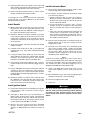
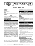
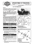
1. Speedometer drive cable
2. Indicator lamps connector [21]
3. Tachometer connector [108]
4. Speedometer connector [20]
5. Speaker switch connector [105]
Figure 4. Instrument Connectors
1998-1999 Models
Remove Ignition Switch
NOTE
For partial disassembly of HDI ignition switch see the Service
Manual.
7.
See Figure 3. Remove the ignition switch knob (2) by
inserting the ignition key switch and turning it to
UNLOCK position. Leaving key installed, rotate the knob
to ACCESS. Depressing the release button (1) at bottom
(left side) with a small screwdriver, push key down and
turn an additional 60 degrees in counter-clockwise
direction. Lift and remove knob.
8.
Using a 7/8 inch wrench on flats, loosen nut (3) and
remove from threaded post of ignition switch housing.
Remove collar (4) and spacer (5).
9.
Remove the switch position plate from threaded post of
ignition switch housing.
If relocating odometer reset switch to left nacelle
switch panel remove reset switch from right front of
right nacelle: 1998- Thread off knurled nut to free
odometer reset knob. 1999- Tread off rubber boot.
Pull reset knob (with rubber washer) from hole in
instrument nacelle.
6.
To remove the bezel, disconnect the instruments from
the jumper harness. Depress button on plug side of the
connector and separate pin and socket halves.
a. Speedometer connector [20] (1), 3-place Multilock
b. Tachometer connector [108], 6-place Multilock
c. Indicator Lamps connector [21] 10-place Multilock
-J01793
2 of 9
Remove LH Nacelle Half
10. See Figure 4. Press button on plug side of speaker
switch connector [105] to separate the left side nacelle
switches from the jumper harness.
Install Bezel
25. See Figure 4. Mate pin and socket halves of the
indicator lamps and instrument connectors to the jumper
harness.
11. Use a T40 TORX drive head to remove two bolts to
release left side of instrument nacelle from fork side.
a. Indicator lamps connector [21], 10-place Multilock
12. Remove left half of nacelle with switch wiring.
c. Speedometer connector [20], 3-place Multilock
13. Gently bend back molded retainer to release switch
bracket assembly from nacelle half.
NOTE
If installing both a left (LH) nacelle half and a right (RH)
nacelle half refer to the Service Manual for nacelle removal
and replacement procedures.
Install Nacelle
14. Obtain replacement nacelle half (LH) from kit and plug
(Part No. 789) for the clutch cable clip hole and plug
(Part No. 728) for the odometer reset switch hole.
15. See Figure 2. Plug the clutch cable clip hole (1) and plug
the unused odometer reset hole. If necessary, use a
circular file to ream the holes in the nacelle and fit the
plugs to the holes.
b. Tachometer connector [108], 6-place Multilock
26. Verify that left and right sides of instrument nacelle are
properly mated. Pins on left side must fully engage holes
on right.
27. Insert tab at rear of bezel into slot of instrument nacelle
(just above ignition switch). Holding left and right sides of
nacelle together, place bezel over instrument nacelle
flange. When properly mated, tabs on each side of the
instrument nacelle engage lip in slot at top of bezel
(behind decorative adhesive strip).
NOTE
If tabs do not properly engage slot at top of bezel, then a
loose fit will result. Remove decorative adhesive strip by
gently prying up outer edges, and using a flat bladed
screwdriver, carefully raise tabs so that they engage lip in
slot. If damaged, install new decorative adhesive strip.
16. Snap switch bracket and switch assembly (4) into
molded retainer in nacelle.
28. Using a T25 TORX drive head, install screw on each
side of bezel. Tighten screws to 25-35 in-lbs (2.8-4.0
Nm).
17. See Figure 4. Carefully fit left nacelle to motorcycle.
Mate speaker switch connector [105] to jumper harness.
29. Move handlebars stop to stop in left and right directions
making sure movement is free (not binding).
18. Verify that left and right sides of nacelle are properly
mated. Four pins on left side of nacelle must fully
engage holes on right.
30. Reconnect negative battery cable.
19. Using T40 TORX drive head, install two bolts (with flat
washers) to fasten instrument nacelle (LH) to fork side.
Tighten bolts to 15-20 ft-lbs (20-27 Nm).
20. Slide odometer reset knob (with rubber washer) through
selected odometer reset switch hole. 1998-Thread
knurled knob on to secure reset knob. 1999- Thread
rubber boot on to secure reset knob.
31. Install seat.
1WARNING
Pull up on seat to verify that it is properly secured, front
and rear. A loose seat may shift during vehicle operation
and startle the rider, possible causing loss of vehicle
control, which could result in death or serious injury.
(00070a)
21. Insert pin of speedometer drive into speedometer gauge
and rotate knurled knob until tight.
Install Ignition Switch
22. Install switch position plate onto threaded post of ignition
switch housing. Tabs on plate fit in holes at top of
nacelle halves.
23. See Figure 2. Slide spacer (5) over threaded post of
ignition switch housing until it contacts switch position
plate. Slide collar (4) over post with tab side down (and
forward) (6). Install nut (3), and using a 7/8 inch wrench
on flats, tighten to 50-70 in-lbs (5.7-7.9 Nm).
24. With the red arrow pointing toward the ACCESS
position, install the ignition switch knob. Turn key
clockwise to UNLOCK position and then turn knob to
OFF.
-J01793
3 of 9
2000-2002 FLTR/I Nacelle (LH) Replacement Instructions
Installation
i05044
1WARNING
1
The rider’s safety depends upon the correct installation
of this kit. Use the apropriate service manual procedures. If the procedure is not within your capabilities or
you do not have the correct tools, have a HarleyDavidson dealer perform the installation. Improper
installation of this kit could result in death or serious
injury. (00333a)
3
1WARNING
To protect against accidental vehicle start-up of vehicle,
which could cause death or serious injury, disconnect
negative (-) battery cable before proceeding. (00048a)
1.
Remove seat to provide access to battery and disconnect the negative battery cable.
4
Remove Instrument Bezel
2.
See Figure 1. Using a T25 TORX drive head, remove
screw on left and right side of instrument bezel.
3.
Use thumbs to push tab at rear of bezel from slot above
ignition switch. Gently raise free side of bezel until tabs
on left and right sides of instrument nacelle become
disengaged from slot at top of bezel (slot is concealed
behind decorative adhesive strip).
4.
Lift the bezel and instrument wiring from the nacelle.
5.
See Figure 5. To remove bezel, separate instrument and
indicator lamp connectors from jumper harness.
a. Depress clear plastic latch on secondary lock to
release speedometer connector [39], 12-place
Packard, at back of speedometer.
b. Tachometer connector [108], 6-place Packard, is a
friction fit with no external latches; to avoid damage to
wire terminals, pull on connector housing to remove.
c. Cut cable strap between speedometer and tachometer brackets and separate indicator lamps connector
[21], 10-place Multilock.
Remove Ignition Switch
Note
For partial disassembly of HDI ignition switch see the Service
Manual.
6.
7.
See Figure 3. Remove the ignition switch knob (2) by
inserting the ignition key switch and turning it to
UNLOCK position. Leaving key installed, rotate the knob
to ACCESS. Depressing the release button (1) at bottom
(left side) with a small screwdriver, push key down and
turn an additional 60 degrees in counter-clockwise
direction. Lift and remove knob.
2
5
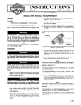
1. Speedometer connector [39]
2. Tachometer connector [108]
3. Indicator lamps connector[21]
4. Odometer reset switch
5. Speaker switch connector[105]
Figure 5. Instrument Connectors
2000-2002 Models
8.
Remove the switch position plate from threaded post of
ignition switch housing.
Remove Nacelle Half (LH)
9.
See Figure 5. Press button on plug side of speaker
switch connector [105] to separate the left side nacelle
switches from the jumper harness.
10. At lower right side of instrument nacelle, unthread rubber
boot to free odometer reset switch. Pull switch from hole
instrument nacelle.
11. Using a T40 TORX drive head, remove two bolts (with
flat washers) to release left side of instrument nacelle
from upper and lower fork brackets.
12. Gently bend back molded retainer to release switch
bracket assembly from instrument nacelle.
NOTE
If installing both a left (LH) nacelle half and a right (RH)
nacelle half refer to the Service Manual for nacelle removal
and replacement procedures.
Using a 7/8 inch wrench on flats, loosen nut (3) and
remove from threaded post of ignition switch housing.
Remove collar (4) and spacer (5).
-J01793
4 of 9
Install Nacelle
Install Instrument Bezel
13. Obtain replacement nacelle half (LH) from kit and the
plug (Part No. 789) for the clutch cable clip hole or the
clutch cable clip (Part No. 70385-01) and the plug (Part
No. 728) for the odometer reset switch hole.
23. See Figure 5. Route speaker switch wiring and mate
speaker switch connector [105], 4-place Multilock.
14. Determine whether to install the odometer reset switch
in the either the right front nacelle half or the left nacelle
switch panel. If necessary, use a circular file to ream the
unused hole to precisely fit the plug (Part No. 728) to the
unused hole.
a. Position indicator lamps connector [21], 10-place
Multilock, between speedometer and tachometer
brackets and secure using new cable strap. Cut any
excess cable strap material.
15. Snap the switch bracket and switch assembly into
molded retainer in nacelle.
16. If using left nacelle switch panel hole for reset switch,
route switch with wiring under the side of the bracket
and into the hole while holding left nacelle half in place.
Install rubber boot.
17. Verify that the left nacelle half is aligned to the right.
Four pins on the left side of the nacelle must fully
engage holes on right.
18. Using a T40 TORX drive head, install two bolts (with flat
washers) to fasten left nacelle half to upper and lower
fork brackets. Be sure to capture clutch cable clip when
installing upper bolt. Alternately tighten bolts to 15-20 ftlbs (20-27 Nm).
19. Determine whether to install the clutch cable clip (Part
No. 70385-01) or the plug to fill the hole. If necessary,
use a circular file to ream the clutch cable hole in the
nacelle to precisely fit the plug (Part No. 789).
Install Ignition Switch
20. Install switch position plate onto threaded post of ignition
switch housing. Tabs on plate fit in holes at top of
nacelle halves.
21. See Figure 2. Slide spacer (5) over threaded post of
ignition switch housing until it contacts switch position
plate. Slide collar (4) over post with tab side down (and
forward) (6). Install nut (3), and using a 7/8 inch wrench
on flats, tighten to 50-70 in-lbs (5.7-7.9 Nm).
22. With the red arrow pointing toward the ACCESS
position, install the ignition switch knob. Turn key
clockwise to UNLOCK position and then turn knob to
OFF.
-J01793
24. Mate instrument and indicator lamp connectors to
interconnect harness:
b. Install speedometer connector {39}, 12-place Packard
at back of speedometer until clear plastic latch on
secondary lock “clicks” into the locked position.
c. Take note of the offset terminal when mating pin and
socket halves of tachometer connector [108], 12place Packard. Using thumbs of both hands, push on
each side of connector until tight. Connector is a friction fit with no external latches.
25. Verify that left and right sides of instrument nacelle are
properly mated. Pins on left half of nacelle must fully
engage holes on right.
26. Insert tab at rear of bezel into slot of instrument nacelle
(just in front of ignition switch). When properly mated,
tabs at front instrument nacelle engage lip in slit at front
of bezel (behind decorative adhesive strip).
NOTE
If tabs do not properly engage slot at front of bezel, then a
loose fit will result. Remove decorative adhesive strip by gently prying up outer edges, and using a flat bladed screw driver, carefully raise tabs so that they engage lip in slot. If
damaged, install new decorative adhesive strip.
27. Using a T25 TORX drive head, install screw on each
side of bezel. Tighten screws to 25-35 in-lbs (2.8-4.0
Nm).
28. Move handlebars stop to stop in left and right directions
making sure movement is free (not binding).
29. Reconnect negative battery cable.
30. Install seat.
1WARNING
Pull up on seat to verify that it is properly secured, front
and rear. A loose seat may shift during vehicle operation
and startle the rider, possible causing loss of vehicle
control, which could result in death or serious injury.
(0007a)
5 of 9
2003 FLTR/I Nacelle LH Replacement Instructions
Installation
i05045
1
1WARNING
4
The rider’s safety depends upon the correct installation
of this kit. Use the apropriate service manual
procedures. If the procedure is not within your
capabilities or you do not have the correct tools, have a
Harley-Davidson dealer perform the installation.
Improper installation of this kit could result in death or
serious injury. (00333a)
3
2
1WARNING
To protect against accidental vehicle start-up of vehicle,
which could cause death or serious injury, disconnect
negative (-) battery cable before proceeding. (00048a)
1.
Remove seat to provide access to battery and disconnect the negative battery cable.
Remove Instrument Bezel
2.
See Figure 1. Using a T25 TORX drive head, remove
screw on left and right side of instrument bezel.
3.
Use thumbs to push tab at rear of bezel from slot above
ignition switch. Gently raise free side of bezel until tabs
on left and right sides of instrument nacelle become
disengaged from slot at top of bezel (slot is concealed
behind decorative adhesive strip).
4.
Lift the bezel and instrument wiring from the nacelle.
NOTE
2003 models are equipped with electronic speedometer. The
odometer reset switch is mounted in the switch panel on the
left nacelle half. The tachometer and speedometer are wired
directly to main harness. The indicator lamps are wired to a
jumper harness
5.
5
1. Speedometer connector [39]
2. Tachometer connector [108]
3. Indicator lamps connector [21]
4. Odometer reset switch conduit
5. Speaker switch connector [105]
Figure 6. Connectors (behind instrument bezel)
2003 Model
6.
See Figure 3. Remove the ignition switch knob (2) by
inserting the ignition key switch and turning it to
UNLOCK position. Leaving key installed, rotate the knob
to ACCESS. Depressing the release button (1) at bottom
(left side) with a small screwdriver, push key down and
turn an additional 60 degrees in counter-clockwise
direction. Lift and remove knob.
a. Depress clear plastic latch on secondary lock to
release speedometer connector [39], 12-place
Packard, at back of speedometer.
7.
Using a 7/8 inch wrench on flats, loosen nut (3) and
remove from threaded post of ignition switch housing.
Remove collar (4) and spacer (5).
b. Tachometer connector [108], 6-place Packard is a
friction fit with no external latches; to avoid damage to
wire terminals, pull on connector housing to remove.
8.
Remove the switch position plate from threaded post of
ignition switch housing.
c. Cut cable strap between speedometer and tachometer brackets and disconnect indicator lamps connector
[21], 10-place Multilock.
Remove Nacelle Half (LH)
See Figure 6. Separate instrument and indicator lamp
connectors from interconnect harness:
Remove Ignition Switch
NOTE
For partial disassembly of HDI ignition switch see the Service
Manual.
-J01793
9.
See Figure 6. Separate speaker switch connector [105]
to disconnect the left side nacelle switches from the
interconnect harness.
10. Using a T40 TORX drive head, remove two bolts (with
flat washers) to release left side of instrument nacelle
from upper and lower fork brackets.
6 of 9
11. Unthread rubber boot from odometer reset switch and
while carefully removing left side instrument nacelle from
motorcycle, pull odometer reset switch from hole.
12. Gently bend back molded retainer to release switch
bracket assembly from instrument nacelle.
NOTE
If installing both a left (LH) nacelle half and a right (RH)
nacelle half refer to the Service Manual for nacelle removal
and replacement procedures.
Install Nacelle
13. Obtain replacement nacelle half (LH) from kit and the
plug (Part No. 789) for the clutch cable clip hole or the
clutch cable clip (Part No. 70385-01) and the plug (Part
No. 728) for the odometer reset switch hole.
14. Determine whether to install the odometer reset switch
in the either the right front nacelle half or the left nacelle
switch panel. If necessary, use a circular file to ream the
unused hole and precisely fit the plug (Part No. 728) to
the unused hole.
15. Snap switch bracket and switch assembly into molded
retainer in nacelle.
16. Carefully fit left nacelle half to right. If using right front
odometer reset hole, route switch and wiring and install
rubber boot
17. If using left nacelle switch panel hole, route switch and
wiring under the left side of the switch bracket and slide
odometer reset switch through hole while carefully
placing the nacelle half in place. Install rubber boot.
18. Verify that left nacelle half is aligned to right. Four pins
on the left side of the nacelle must fully engage holes on
right.
19. Using a T40 TORX drive head, install two bolts (with flat
washers) to fasten left nacelle half to upper and lower
fork brackets. Be sure to capture clutch cable clip when
installing upper bolt. Alternately tighten bolts to 15-20 ftlbs (20-27 Nm).
20 Determine whether to install the clutch cable clip (Part
No. 70385-01) or the plug (Part No. 789) to fill the hole.
If necessary, use a circular file to ream the clutch cable
hole in the nacelle to precisely fit the plug.
Install Ignition Switch
21. Install switch position plate onto threaded post of ignition
switch housing. Tabs on plate fit in holes at top of
nacelle halves.
22. See Figure 2. Slide spacer (5) over threaded post of
ignition switch housing until it contacts switch position
plate. Slide collar (4) over post with tab side down (and
forward) (6). Install nut (3), and using a 7/8 inch wrench
on flats, tighten to 50-70 in-lbs (5.7-7.9 Nm).
Install Instrument Bezel
24. Route speaker switch wiring and mate speaker switch
connector [105] halves (4-place Multilock).
25. See Figure 6. Connect instruments and indicator lamps
to in interconnect harness:
a. Position Indicator lamps connector [21], 10-place
Multilock, between speedometer and tachometer
brackets and secure using new cable strap. Cut any
excess cable strap material.
b. Install speedometer connector {39}, 12-place
Packard, at back of speedometer until clear plastic
latch on secondary lock “clicks” into the locked position.
c. Take note of the offset terminal when mating pin and
socket halves of tachometer connector [108], 12place Packard. Using thumbs of both hands, push on
each side of connector until tight. Connector is a friction fit with no external latches.
26. Verify that left and right sides of instrument nacelle are
properly mated. Pins on left half of nacelle must fully
engage holes on right.
27. Insert tab at rear of bezel into slot of instrument nacelle
(just in front of ignition switch). Holding left and right
sides of nacelle together, place bezel over instrument
nacelle flange. When properly mated, tabs at front
instrument nacelle engage lip in slit at front of bezel
(behind decorative adhesive strip).
NOTE
If tabs do not properly engage slot at front of bezel, then a
loose fit will result. Remove decorative adhesive strip by gently prying up outer edges, and using a flat bladed screw driver, carefully raise tabs so that they engage lip in slot. If
damaged, install new decorative adhesive strip.
28. Using a T25 TORX drive head, install screw on each
side of bezel. Tighten screws to 25-35 in-lbs (2.8-4.0
Nm).
29. Move handlebars stop to stop in left and right directions
making sure movement is free (not binding).
30. Reconnect negative battery cable.
31. Install seat.
1WARNING
Pull up on seat to verify that it is properly secured, front
and rear. A loose seat may shift during vehicle operation
and startle the rider, possible causing loss of vehicle
control, which could result in death or serious injury.
(0007a)
23. With the red arrow pointing toward the ACCESS
position, install the ignition switch knob. Turn key
clockwise to UNLOCK position and then turn knob to
OFF.
-J01793
7 of 9
2004 FLTR/I Instrument Nacelle (LH) Replacement Instructions
Installation
i06192
1WARNING
4
The rider’s safety depends upon the correct installation
of this kit. Use the apropriate service manual
procedures. If the procedure is not within your
capabilities or you do not have the correct tools, have a
Harley-Davidson dealer perform the installation.
Improper installation of this kit could result in death or
serious injury. (00333a)
2
3
1WARNING
To protect against accidental vehicle start-up of vehicle,
which could cause death or serious injury, disconnect
negative (-) battery cable before proceeding. (00048a)
1.
Remove seat to provide access to battery and disconnect the negative battery cable.
Remove Instrument Bezel
5
1
2.
See Figure 1. Using a T25 TORX drive head, remove
screw on left and right side of instrument bezel.
3.
Use thumbs to push tab at rear of bezel from slot above
ignition switch. Gently raise free side of bezel until tabs
on left and right sides of instrument nacelle become
disengaged from slot at top of bezel (slot is concealed
behind decorative adhesive strip).
4.
Raising bezel slightly, remove anchor on ambient
temperature sensor from hole in bottom inboard ear of
speedometer bracket.
5.
Lift the bezel and instrument wiring from the nacelle.
Remove Ignition Switch
6.
See Figure 7. Separate instrument and indicator lamp
connectors from interconnect harness:
NOTE
For partial disassembly of HDI ignition switch see the Service
Manual.
a. Speedometer connector [39] 12-place Packard
b. Tachometer connector [108] 12-place Packard
1. Ambient temperature sensor connector[107]
2. Speedometer connector [39]
3. Tachometer connector [108]
4. Indicator lamps connector [21]
5. Speaker switch connector [105]
Figure 7. Connectors (behind instrument bezel)
2004 Model
7.
See Figure 3. Remove the ignition switch knob (2) by
inserting the ignition key switch and turning it to
UNLOCK position. Leaving key installed, rotate the knob
to ACCESS. Depressing the release button (1) at bottom
(left side) with a small screwdriver, push key down and
turn an additional 60 degrees in counter-clockwise
direction. Lift and remove knob.
8.
Using a 7/8 inch wrench on flats, loosen nut (3) and
remove from threaded post of ignition switch housing.
Remove collar (4) and spacer (5).
9.
Remove the position plate from threaded post of ignition
switch housing.
c. Indicator lamps connector [21] 10-place Multilock
NOTE
2004 models are equipped with electronic speedometer. The
odometer reset switch is mounted on front of left side of
bezel. The tachometer and speedometer are wired directly to
main harness. The indicator lamps are wired directly to the
interconnect harness. There is no “jumper harness”.
-J01793
8 of 9
Remove Nacelle Half (LH)
Install Instrument Bezel
10. See Figure 7. Separate speaker switch connector [105]
to disconnect the left side nacelle switches from the
interconnect harness.
24. See Figure 7. Connect instruments and indicator lamps
to in interconnect harness:
11. Pull clutch cable clip from hole on left side of instrument
nacelle.
a. Speedometer connector {39}, 12-place Packard
b. Tachometer connector [108], 12-place Packard
c. Indicator lamps connector [21] 10-place Multilock
12. Unthread rubber boot from odometer reset switch, and
while carefully removing left instrument nacelle from
motorcycle, pull odometer reset switch from hole.
25. Install anchor on ambient temperature sensor into hole
in bottom ear of speedometer bracket.
13. Gently bend back molded retainer to release switch
bracket assembly from instrument nacelle.
26. Verify that left and right sides of instrument nacelle are
properly mated. Pins on left half of nacelle must fully
engage holes on right.
14. Using a T40 TORX drive head, remove two bolts (with
flat washers) to release left side of instrument nacelle
from upper and lower fork brackets.
NOTE
If installing both a left (LH) nacelle half and a right (RH)
nacelle half refer to the Service Manual for nacelle removal
and replacement procedures.
Install Nacelle
15. Obtain replacement nacelle half (LH) from kit
16. Snap switch bracket and switch assembly into molded
retainer in nacelle.
17. While carefully placing the nacelle half in place, slide
odometer reset switch through hole and install rubber
boot.
18. Route speaker switch wiring and mate speaker switch
connector [105] halves (4-place Multilock).
19. Verify that left nacelle half is aligned to right. Four pins
on the left side of the nacelle must fully engage holes on
right. Using a T40 TORX drive head, install two bolts
(with flat washers) to fasten left nacelle half to upper and
lower fork brackets. Alternately tighten bolts to 15-20 ftlbs (20-27 Nm).
20. Capture clutch cable in cable clip and install cable clip
into hole in left nacelle half.
Install Ignition Switch
27. Insert tab at rear of bezel into slot of instrument nacelle
(just in front of ignition switch). Holding left and right
sides of nacelle together, place bezel over instrument
nacelle flange. When properly mated, tabs at front
instrument nacelle engage lip in slit at front of bezel
(behind decorative adhesive strip).
NOTE
If tabs do not properly engage slot at front of bezel, then a
loose fit will result. Remove decorative adhesive strip by gently prying up outer edges, and using a flat bladed screw driver, carefully raise tabs so that they engage lip in slot. If
damaged, install new decorative adhesive strip.
28. Using a T25 TORX drive head, install screw on each
side of bezel. Tighten screws to 25-35 in-lbs (2.8-4.0
Nm).
29. Move handlebars stop to stop in left and right directions
making sure movement is free (not binding).
30. Reconnect negative battery cable.
31. Install seat.
1WARNING
Pull up on seat to verify that it is properly secured, front
and rear. A loose seat may shift during vehicle operation
and startle the rider, possible causing loss of vehicle
control, which could result in death or serious injury.
(0007a)
21. Install switch position plate onto threaded post of ignition
switch housing. Tabs on plate fit in holes at top of
nacelle halves.
22. See Figure 2. Slide spacer (5) over threaded post of
ignition switch housing until it contacts switch position
plate. Slide collar (4) over post with tab side down (and
forward) (6). Install nut (3), and using a 7/8 inch wrench
on flats, tighten to 50-70 in-lbs (5.7-7.9 Nm).
23. With the red arrow pointing toward the ACCESS
position, install the ignition switch knob. Turn key
clockwise to UNLOCK position and then turn knob to
OFF.
-J01793
9 of 9