1
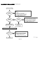
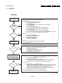
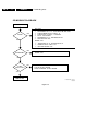
Faultfinding Guide
CDR775
8.2
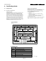
Power Supply Unit 20PS317
8.2.1
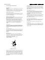
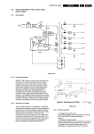
Description of PSU 20PS317
Rectifier
5131
6102
EMI
FILTER
MAINS
GB 53
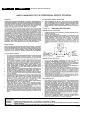
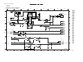
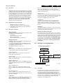
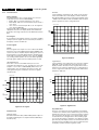
cycle is regulated so that the output voltages are independent
of load or input voltage variations. The controlling device
MC44603 is an integrated pulse width modulator. A clock
signal initiates power pulses at a fixed frequency. The
termination of each output pulse occurs when a feedback
signal of the inductor current reaches a threshold set by the
error signal. In this way the error signal actually controls the
peak inductor current on cycle-by-cycle basis.
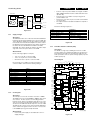
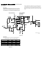
MOSFET 7125 is used as a power switch controlled by the
controller IC7110. When the switch is closed, energy is
transferred from mains to the transformer. This energy is
supplied to the load when the switch is opened. Through
control of the switch-on time, the energy transferred in each
Lightning
Protection
8.
6210/6211
17
+5V
2210
2
15
2121
6230/6232
11
+12V
5
2230
7125
13
7249
6240
-8V
2240
10
Rsense
6132
6250
7251
14
6129
VFTD
2250
6201
7110
Supply Init
2.5V
Error
Amplifier
Current
Sense
Input
+
-
OSC.
7252
Demagnet.
Mgmt
Output
Sense
+
Vc
R
Q
latch
Buffer
7221
6220
7
S
16
VDC2
Out
Gnd
9
2220
18
Voltage
Feedback
Soft-Start
Control
Overvoltage
Mgmt
VDC1
7200
7201
GND
GND
REGULATION
CL 96532076_029.eps
290799
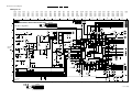
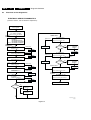
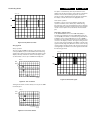
Figure 8-10 ‘Blockdiagram PSU 20PS317’
Description of controller MC44603
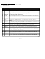
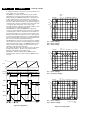
The MC44603 is an enhanced high performance controller that
is specifically designed for off-line and DC-to-DC converter
applications. This device has the unique ability of automatically
changing operating modes if the converter output is
overloaded, unloaded or shorted. The MC44603 has several
distinguishing features when compared to conventional SMPS
controllers. These features consist of a foldback facility for
overload protection, a standby mode when the converter output
is slightly loaded, a demagnetization detection for reduced
switching stresses on transistor and diodes, and a high current
totem pole output ideally suited for driving a power MOSFET. It
can also be used for driving a bipolar transistor in low power
converters. It is optimised to operate in discontinuous mode but
can also operate in continuous mode. Its advanced design
allows use in current mode or voltage mode control
applications.
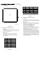
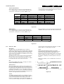
Pin connections
VCC
1
16
Rref
VC
2
15
R Frequency Standby
Output
3
14
Voltage feedback Input
Gnd
4
13
Error Amp Output
Foldback Input
5
12
R Power Standby
Overvoltage Protection (OVP)
6
11
Soft-Start/Dmax/
Voltage Mode
Current Sense Input
7
10
CT
Demag. Detection
8
9
Sync Input
CL 96532076_030.eps
290799
Figure 8-11