1
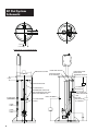
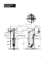
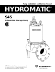
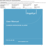
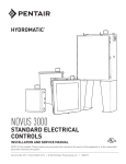
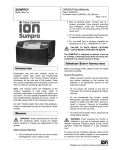
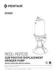
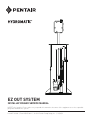
EZ OUT SYSTEM INSTALLATION AND SERVICE MANUAL NOTE! To the installer: Please make sure you provide this manual to the owner of the equipment or to the responsible party who maintains the system. Item # E-03-389 | Part # 5625-389-1 | © 2012 Pentair Pump Group, Inc. | 10/30/12 CALIFORNIA PROPOSITION General65 WARNING: Information This Thank you for purchasing your Hydromatic® pump. To help ensure years of trouble-free operation, please read the following manual carefully. Before Operation: Read the following in struc tions caref ull y. Reasonable care and safe meth ods should be practiced. Check local codes and requirements before installation. Attention: This manual contains important information for the safe use of this product. Read this manual completely before using this product and refer to it often for con tin ued safe product use. DO NOT THROW AWAY OR LOSE THIS MANUAL. Keep it in a safe place so that you may refer to it often. Unpacking Pump: Remove pump from carton. When unpacking unit, check for con cealed damage. Claims for damage must be made at the receiving end through the delivery carrier. Dam age cannot be processed from the factory. WARNING: Before handling these pumps and controls, always disconnect the power first. Do not smoke or use sparkable electrical devices or flames in a septic (gaseous) or possible septic sump. 2 product and related accessories contain chemicals known to the State of California to cause cancer, birth defects or other reproductive harm. Lift-Out Coupling Models: These instructions cover the entire range of lift-out couplings offered. Most lift-out couplings are designed for pumps with vertical discharge; as well, we now offer our newest lift-out coupling designed for 2-1/2" and 3" discharge. General Construction: The standard lift-out coupling base as well as the slide plate assembly is made of cast iron. The guide plate is made of galvanized steel. The guide plate, top rail support and intermediate rail support are made of galvanized steel with the option of stainless steel. The slide plate assembly is also available in optional stainless steel and nonsparkling brass. Lift-Out Chain: The two chain packages available are galvanized and stainless steel. Each package is designed to attach to the top of the pump and also to the guide plate. Each package is designed to allow the pump to be safely hoisted up the guide rails. Rail Support Bracket: All the lift-outs are designed to use 1/2" standard pipe for guide rails. A top rail support is available to be mounted to the hatch frame. Intermediate brackets are available for deep installations. It is recommended that if the rail length is over 12 feet, an intermediate bracket be installed. Pump Installation Installing Rail System Parts Discharge Base and Rails: 1.Lower the base elbow into the basin. 2.Position the base elbow by dropping a plumb line from the center of the pipe supports, located on top rail support, to center of rail pins protruding from the base elbow. Level the elbow flange in two directions 90° to each other. Mark the position of the base hold-down bolts through the holes in the base. 3.Move the base aside to allow for installation of mounting bolts (not included). Secure base to mounting bolts. 4. Cut the pipe guide rails (supplied by others) to the proper length and install them between the pipe supports at the top of the basin and the pins on the base. It is recommended that the guide rails be schedule 40, galvanized or stainless steel. IMPORTANT: Discharge pipe and guide rails must be parallel if intermediate guide bracket is used. Installing Intermediate Guide Bracket (required for each 12 feet of basin depth) 1. Remove guide rails and cut a piece from each one. These pipes must be exactly the same length and of a length that will permit installing the intermediate guide bracket in the desired location. 2.Place the cut pieces of pipe over the guide rail pins located in the base. 3.Set the intermediate guide bracket in position with guides into pipe. Put U-bolt around discharge pipe and tighten lightly. 4.Measure from joint on plug on intermediate guide bracket to joint on plug on top rail support and cut two (2) rails to the length. Put rails in place and tighten screws in top of rail support. 5.Recheck rails; they must be straight and plumb. Move intermediate guide bracket if necessary to perfectly align the rails after alignment is secured; tighten nuts on U-bolt. 6. If a second intermediate guide bracket is used, the above procedure is followed for installation. An additional clevis hook is provided with the chain package to be fastened on the top rail support to hold the upper end of the chain when not in use. Position pump so the guide rails are located in the slots of the guide plate. Slowly lower the pump down the guide rails to the base. The locating pins (horizontal pins on sealing plate) should come to seat in the inclined surface on the arms. IMPORTANT: When using the lift-out check valve option – recommend 3–5' per second, maximum velocity (all models). Attaching Disconnect to Pump 1.Remove close quarter elbow from sealing plate. Three cap screws hold elbow to sealing plate. 2.Thread elbow into pump volute. 3. Bolt on sealing plate. 4. Set lifting chain bail with one (1) end on guide plate eyebolt and the other end on pump lifting eye. Installing Pump and Disconnect Attach the lifting chain to the bail with clevis, sliding the clevis along bail until the center of gravity is found. 3 EZ Out System Schematic 3-1/2 7 1-11/16 5-11/16 COVER DETAIL w/ SYSTEM REMOVED FIBERGLASS COVER 24" MIN. DIA. UPPER RAIL BRACE STAINLESS STEEL FLOAT BRACKET STAINLESS STEEL GATE VALVE EXTENSION HANDLE 6 STD. SUPPORT BRACING 3/4" GUIDE RAILS INTERMEDIATE GUIDE RAIL BRACE REQUIRED FOR TANK DEPTHS EXCEEDING 12'0" ALARM LEVEL (OPTIONAL) PUMP ON PUMP OFF 4 INLET GROMMET PVC DISCHARGE PIPING 1-1/4" BRASS GATE VALVE 1-1/4" STAINLESS STEEL DISCHARGE HUB PVC BALL CHECK VALVE w/ CLEANOUT EZ Out System Schematic 45° FIBERGLASS COVER UPPER RAIL BRACE THERMOPLASTIC JUNCTION BOX 10 STD. 14 STD. STAINLESS STEEL GATE VALVE EXTENSION HANDLE STAINLESS STEEL FLOAT BRACKET SUPPORT BRACING 2" NPT ELECTRICAL HUB FLOAT BRACKET ROTATED 45° OUT OF TRUE POSITION ALARM LEVEL (OPTIONAL) 3/4" GUIDE RAILS INTERMEDIATE GUIDE RAIL BRACE REQUIRED FOR TANK DEPTHS EXCEEDING 12'0" INLET GROMMET PVC DISCHARGE PIPING 1-1/4" BRASS GATE VALVE 1-1/4" STAINLESS STEEL DISCHARGE HUB PVC BALL CHECK VALVE w/ CLEANOUT PUMP ON PUMP OFF 12-1/16 5 THIS PAGE INTENTIONALLY LEFT BLANK 6 THIS PAGE INTENTIONALLY LEFT BLANK 7 STANDARD LIMITED WARRANTY Pentair Hydromatic® warrants its products against defects in material and workmanship for a period of 12 months from the date of shipment from Pentair Hydromatic or 18 months from the manufacturing date, whichever occurs first – provided that such products are used in compliance with the requirements of the Pentair Hydromatic catalog and technical manuals for use in pumping raw sewage, municipal wastewater or similar, abrasive-free, noncorrosive liquids. During the warranty period and subject to the conditions set forth, Pentair Hydromatic, at its discretion, will repair or replace to the original user, the parts that prove defective in materials and workmanship. Pentair Hydromatic reserves the right to change or improve its products or any portions thereof without being obligated to provide such a change or improvement for prior sold and/or shipped units. Start-up reports and electrical schematics may be required to support warranty claims. Submit at the time of start up through the Pentair Hydromatic website: http://forms.pentairliterature.com/startupform/startupform.asp?type=h. Warranty is effective only if Pentair Hydromatic authorized control panels are used. All seal fail and heat sensing devices must be hooked up, functional and monitored or this warranty will be void. Pentair Hydromatic will cover only the lower seal and labor thereof for all dual seal pumps. Under no circumstance will Pentair Hydromatic be responsible for the cost of field labor, travel expenses, rented equipment, removal/reinstallation costs or freight expenses to and from the factory or an authorized Pentair Hydromatic service facility. This limited warranty will not apply: (a) to defects or malfunctions resulting from failure to properly install, operate or maintain the unit in accordance with the printed instructions provided; (b) to failures resulting from abuse, accident or negligence; (c) to normal maintenance services and parts used in connection with such service; (d) to units that are not installed in accordance with applicable local codes, ordinances and good trade practices; (e) if the unit is moved from its original installation location; (f) if unit is used for purposes other than for what it is designed and manufactured; (g) to any unit that has been repaired or altered by anyone other than Pentair Hydromatic or an authorized Pentair Hydromatic service provider; (h) to any unit that has been repaired using non factory specified/ OEM parts. Warranty Exclusions: Pentair HYDROMATIC MAKES NO EXPRESS OR IMPLIED WARRANTIES THAT EXTEND BEYOND THE DESCRIPTION ON THE FACE HEREOF. Pentair HYDROMATIC SPECIFICALLY DISCLAIMS THE IMPLIED WARRANTIES OF MERCHANTABILITY AND FITNESS FOR ANY PARTICULAR PURPOSE. Liability Limitation: IN NO EVENT SHALL Pentair HYDROMATIC BE LIABLE OR RESPONSIBLE FOR CONSEQUENTIAL, INCIDENTAL OR SPECIAL DAMAGES RESULTING FROM OR RELATED IN ANY MANNER TO ANY Pentair HYDROMATIC PRODUCT OR PARTS THEREOF. PERSONAL INJURY AND/OR PROPERTY DAMAGE MAY RESULT FROM IMPROPER INSTALLATION. Pentair HYDROMATIC DISCLAIMS ALL LIABILITY, INCLUDING LIABILITY UNDER THIS WARRANTY, FOR IMPROPER INSTALLATION. Pentair HYDROMATIC RECOMMENDS INSTALLATION BY PROFESSIONALS. Some states do not permit some or all of the above warranty limitations or the exclusion or limitation of incidental or consequential damages and therefore such limitations may not apply to you. No warranties or representations at any time made by any representatives of Pentair Hydromatic shall vary or expand the provision hereof. 740 EAST 9TH STREET 490 Pinebush Road, Unit #4 ASHLAND, OHIO, USA 44805 CAMBRIDGE, ONTARIO, CANADA N1T 0A5 419-289-1144800-363-PUMP WWW.HYDROMATIC.COM Warranty Rev. 12/13