1
Ring Device
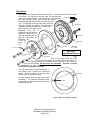
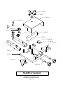
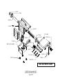
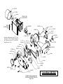
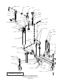
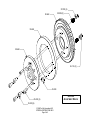
The ring device is composed of three main sections. The base section (50-664) is bolted
to the lathe. The ring portion (50-662) rides over the base and
under the top plate (50-665). The whole device is held together 36-114 (2)
with bolts (35-232) which pass through the device,
through springs (50-055) and into nylon lock nuts (36114). The springs let the top plate move when the
50-664 (2)
ring screw (35-234) is engaged. The whole device
is bolted to the lathe spindle with four socket cap
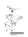
screws (35-233). The bottom of the
adjustment
ring
has
a
machined ridge opposite the
set-screw. When the setscrew is tightened the ring
50-055 (2)
acts like a tripod with one
adjustable leg.
If the set50-664
screw
is
set
exactly
50-662
35-232 (2)
at
the
JBC 520
Adjustment Device
35-234
50-665
high
point of the initial runout, the initial
runout and the adjustment will cancel each other exactly. If
the adjustment screw is not exactly at the high point of the runout the
runout will be reduced, but will never be eliminated. Therefore, accurate
positioning of the ring device is
necessary to compensate for runout.
35-233 (4)
The ring device itself is purely mechanical. It
can function with or without the electronics
system. All that is required of the ring is that
the high point is located accurately.
Ridge
So what happens when the ring is not located
accurately? The following illustrations show
what happens to the total runout when the ring
is incorrectly placed.
Screw
Figure 3 Bottom of Adjustment Ring
©1998 Pro-Cut International LLC
INTERNAL DISTRIBUTION ONLY
Page 2 of 8