1
Common problems include:
♦
♦
♦
♦
♦
Sensor cable frayed or broken
Sensor cable no longer wrapped around the nylon pulley
Sensor cable wrapped around the nylon pulley backwards
Spur wire is disconnected from the shaft encoder or is connected backwards
Sensor cable not connected to the vehicle or not straight
♦
Sensor cable not feeding in and out smoothly
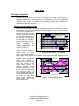
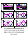
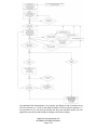
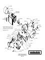
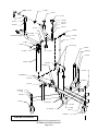
Complaints that they technician cannot get past a yellow light most often point to a
problem with the reel sensor unit. If the motion of the encoder shaft lags behind the
actual motion of the machine the electronics will not report the correct ring position to the
operator. If the ring is incorrectly positioned the LRO will get down to the lowest it can
go, and then the electronics will just change the sign of the LRO, but not the amount.
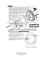
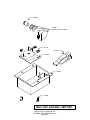
Complaints that the live mode counts up instead of down are because the sensor
cable is wrapped around the pulley backwards. The two ends of the sensor cable as they
come off the nylon pulley should be parallel. The cable starts below the nylon pulley, is
wrapped up and around the pulley one time, and then goes out the keyhole. If the cable
is wrapped the around the pulley in the wrong direction, the cable will come out of
the small rectangular part of the keyhole slot. If the cable is wrapped the around
the pulley in the right direction, the cable will come out circular part of the keyhole.
Use needle-nose pliers to wrap and unwrap the cable around the nylon pulley. Be careful
not to kink the sensor cable.
The Controller:
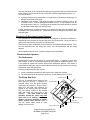
Mounted on the lathe trolley, the controller (computer) is responsible for gathering and
interpreting the data from the tachometer and string reel unit. It then displays the high
point phase (ring position) and lateral runout to the technician.
There are two buttons on the controller. The one on the left is the reset button. This
erases any information in the controller and starts the program at the beginning. It can
be pressed at any time to reset the unit. However, during normal operation, there should
be no need to press this button. The right hand button switches the unit from the
measuring mode to the live adjustment mode and makes the display act like a dial
indicator.
The other features on the controller are the text display and the cable junctions. It is not
possible to mis-wire the controller to the harness to the control unit.
Common problems include:
♦
♦
♦
♦
Cable damage from tension on the wire harness. This is most often caused when
flipping the lathe.
Four black squares, and four blank spaces on the display. A jammed button most
often causes this. Open the electronics box and be sure that the reset and live
adjustment buttons are free to move up and down. Also be sure that either the
sensor is not pressing the button on the backside of the circuit board or power wires.
Works properly on one side but doesn’t on a successive cut. The controller has a 5minute time-out. It will reset itself after 5 minutes of not receiving a tachometer pulse.
If you begin to do a second brake job less than 5 minutes after finishing the first, you
will need to press RESET before you begin. Whenever you begin a brake job the
controller should flash between READY and RELEASE SCREW.
No power at the electronics box/no lights come on. Check AC connections and
power at the wall outlet, inside the motor junction box and at the back of the
electronics box.
©1998 Pro-Cut International LLC
INTERNAL DISTRIBUTION ONLY
Page 5 of 8