1
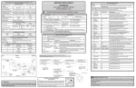
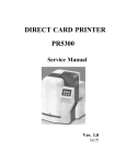
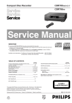
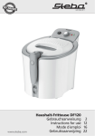
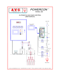
Section 8 - Ice and Water Dispenser
DISPENSER OPERATION
The dispenser has a user interface section in the control
in the door. The auger motor, water valve and cube ice
are all controlled on the lower control board. There are
two connections on the back of the control one is a 115
V AC connection to supply power to operate the door
opening solenoid. The other is a 12 VDC connection
from the lower control board to operated the relay that
controls the door solenoid. (See Figure 7)
The UI Board is Held in place by two tabs
one on each side. Push out on tabs and lift
board off the pins.
115 VAC Black & Blue
12 VDC Brown & Blue
Figure 4
With the frame removed you can turn it around and
remove the molex plugs from the user interface board.
The UI board can now be removed from the frame.
Relay to Control Door
Solenoid
Control Board
for Relay
Figure 7
Disconnect Plugs
Figure 5
With the control removed you can now remove the two
screws holding the dispenser in the housing. (See Figure
6)
When the actuator is pressed a low voltage signal
(12VDC) is sent to the user interface on the upper
control by way of the actuator switch located on the
housing just behind the door solenoid relay. ( See
Figure 8 ) The upper board will send a communication
to the lower board based on the customers selection of
Water, cube ice or crushed ice. If water is selected the
communication will open a tri-ack on the lower board for
the water valve. If ice is selected it will do the same thing
for the auger motor and /or cube ice solenoid.
Remove screws
Figure 6
8:4
Actuator
Figure 6
Actuator Switch