1
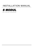
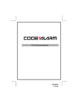
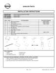
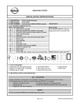
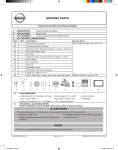
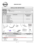
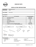
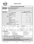
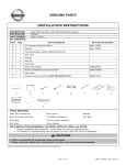
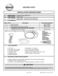
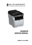
GENUINE PARTS
INSTALLATION INSTRUCTIONS
1. DESCRIPTION:
Vehicle Alarm Impact Sensor
2. APPLICATION:
G37 Coupe (2010)
3. PART NUMBER:
999M2 VU003 OR 999M2 VW002
4. KIT CONTENTS:
Item
QTY
Description
A
1
Impact Sensor
B
1
Harness
C
1
14” Tie Wrap
D
3
8” Tie Wrap
E
3
Posi-Taps®
A
B
C
E
D
NOTE: ITEMS “A” AND “B” ARE PACKAGED AS A SINGLE ASSEMBLY
5. TOOLS REQUIRED:
1. Philips screw driver (#2 short)
2. Clip remover
3. 1/4” driver w/ 10mm socket
4. Plastic pry bar (P/N J-46534 or equivalent)
5. Electrical Tape
6. PRE-INSTALLATION CAUTIONS/NOTES:
Dealer Installation Recommended. Instructions refer to Service Manual.
! CAUTION
• Use caution when removing/re-installing interior components to avoid damage, scratches, or breaking of
mounting clips.
• The following steps are critical and must be performed EXACTLY as specified to ensure proper installation:
• Mounting of the Impact sensor
• Install Posi-Tap.®
4280266
Page 1 of 8
999M2 JW001 REV 1/4/10
VEHICLE ALARM IMPACT SENSOR
7. INSTALLATION OVERVIEW
IMPACT
SENSOR
BCM
IMPACT
SENSOR
4280266
BCM
Page 2 of 8
999M2 JW001 REV 1/4/10
VEHICLE ALARM IMPACT SENSOR
8. VEHICLE PREPERATION
1) Record the customer radio presets.
Preset
1
2
3
4
5
6
7
A
B
C
2) Disconnect the battery negative terminal to prevent short circuits during installation.
Fig. 1
3) Remove passenger instrument lower cover. Fig. 1
a) Pull downward, disengage pawls.
b) Pull back passenger instrument lower cover.
! CAUTION
• Front kicking plate and dash side finisher should be removed as one piece to prevent damage to parts.
Fig. 2
Fig. 3
4) Remove the front kicking plate
inner. Fig. 2
a) Pull up the front kicking plate
inner, and disconnect pawls.
b) Remove the front kicking
plate inner.
5) Remove the dash side finisher. Fig. 3
a) Remove the retaining clip located near the
vehicle dash wall.
b) Disengage the dash side finisher mounting clips
with a remover tool.
c) Remove the dash side finisher panel.
Retaining Clip
4280266
Page 3 of 8
999M2 JW001 REV 1/4/10
VEHICLE ALARM IMPACT SENSOR
9. INSTALLATION PROCEDURE
Fig. 4
1) Connect the Impact Sensor Harness ground. Fig. 4
a) Remove the 10mm bolt located on the
right hand bracket, attached to the BCM.
b) Install the Impact Sensor Harness ground
terminal over the bolt and reinstall into
the BCM bracket.
Ground
2)
Tap the Brown wire of the Impact Sensor Harness to the Green wire, located in cavity 50 of the M121 connector at the BCM. Fig. 5
®
a) See steps 3-7 for Posi-Tap installation instructions.
Fig. 5
M121
Yellow Wire
Green Wire
Cavity 50
4280266
Page 4 of 8
999M2 JW001 REV 1/4/10
VEHICLE ALARM IMPACT SENSOR
Fig. 6
b)
a)
3) Tap vehicle wire. Fig. 6
a) Remove cap (slot side) from tap body.
b) Slide cap around vehicle wire.
c) Tighten the tap TIGHT with finger pressure.
Note:
Do not re-use the tap for subsequent re-installation.
c)
Fig. 7
4) Inspect the tap to ensure correct installation. Fig. 7
Note:
Avoid putting pressure on the vehicle wire and
tap for the rest of the installation.
i. Straight and evenly spaced all the way around.
ii. Tight and minimize gap (wire jacket should be
crushed).
Fig. 8
5) Tap the Red wire from the Impact Sensor Harness.
Fig. 8
a) Remove tap (non-pierce) side from tap.
b) Remove protective stub from Red wire.
c) Insert the Red wire through the non-pierce side
opening.
d) Spread the individual strands into a fan shape.
e) Insert wire into the tap body and ensure that it
is all the way in.
f) Tighten the tap TIGHT with finger pressure.
e)Insert wire to here
c)
a)
d)
f) Tighten
b) Protective Stub
Harness Wire
4280266
Page 5 of 8
999M2 JW001 REV 1/4/10
VEHICLE ALARM IMPACT SENSOR
Fig. 9
6) Confirm installation of the tapped accessory wire.
Fig. 9
a) Inspect the tap to ensure correct installation.
b) Test the signal to ensure that it is working
properly.
Note:
Avoid putting pressure on the vehicle wire and
tap for the rest of the installation.
i. Straight and evenly spaced all the way around.
ii. Tight and no gap
iii. Test the signal
7) Secure the tap. Fig. 10
a) Secure the tapped wire on the non-pierced side
to the body of the posi-tap with electrical tape
_ 2 revolutions).
(>
b) Secure the body to harness where vehicle wire
is being tapped with electrical tape
_ 2 revolutions).
(>
Fig. 10
b)
a)
Existing
harness
Accessory
harness
8) Tap the Red wire of the Impact Sensor Harness to the Red wire, located in cavity 11 of the M119 connector at the
BCM. Fig. 11
®
a) See steps 3-7 for Posi-Tap installation instructions.
M119
Fig. 11
Cavity 11
19 18 17 16 15 14 13 12 11
10 9
8
7
6
5
4
Red Wire
Purple Wire
Green Wire
4280266
Page 6 of 8
Lt. Green Wire
999M2 JW001 REV 1/4/10
VEHICLE ALARM IMPACT SENSOR
9)
Tap the Blue wire of the Impact Sensor Harness to the White wire, located in cavity 123 of the M123 connector at
the BCM. Fig. 12
®
a) See steps 3-7 for Posi-Tap installation instructions.
Fig. 12
M123
Cavity 123
Lt. Green Wire
White Wire
Green Wire
! CAUTION
• Mount Impact Sensor exactly as shown in the Installation Instructions. Failure to do so may affect
performance.
10) Secure the Impact Sensor. Fig. 13
a) Set the sensitivity of the Impact Sensor to “2” prior to mounting.
b) Secure the Impact Sensor with (1) 14”cable tie to the factory harness located to the left of the BCM,
towards the vehicle dash wall. Cable tie should be attached 2cm above the plastic mounting tab securing the factory
harness to the body structure.
c) Trim the excess cable tie end after tightening.
d) Secure the Impact Sensor Harness with (3) cable ties to the factory harness that is connected to the BCM.
e) Trim the excess cable tie end after tightening.
Fig. 13
Mounting Tab
2 cm
Wire Tie
4280266
Page 7 of 8
999M2 JW001 REV 1/4/10
VEHICLE ALARM IMPACT SENSOR
10. FUNCTIONALITY TEST PROCEDURE
1) Reconnect the negative battery cable.
2) Open the driver’s window and exit the vehicle.
3) Close all doors and arm the security system using the transmitter.
4) The security light in the dash should come on solid for 30 seconds and then start to blink.
5) Trigger the security system by slapping the steering wheel.
6) The interior lights should briefly come on and then turn off, and the horn should start honking.
7) Disarm the security system using the transmitter.
8) Close all doors and arm the security system using the transmitter.
9) The security light in the dash should come on solid for 30 seconds and then start to blink.
10) Pull door handle and verify that the interior light does not come on and the horn does not start honking.
11) If necessary, follow section 13 to adjust sensitivity of Impact Sensor
12) Enter the vehicle, close the door and set the IGN Switch to On.
13) Slap the steering wheel with enough force that would trigger the security system.
14) Verify that the interior light does not come on and the horn does not start honking.
11. REINSTALLATION OF REMOVED PARTS
1) Reinstall all removed vehicle parts. Refer to the
service manual for the vehicle as necessary.
2) Be sure to engage all the clips on the interior finish
panels.
3) Reprogram the radio presets.
4) Clean the vehicle interior.
12. FINAL INSPECTION
1) Inspect the vehicle interior and exterior for
damage.
2) Start vehicle and verify that there are no DTC
indicators on the meter.
3) Place the Quick Reference Guide into vehicle’s
glovebox.
13. IMPACT SENSOR ADJUSTMENT PROCEDURE
Fig. 14
IMPACT SENSOR ADJUSTMENT
1) In the event of customer complaint, Please use the
following procedure. Fig. 14
a) Roll the driver’s window down.
b) Close all doors and press the lock button on
the transmitter.
c) Wait until the anti-theft light changes from
solid to blinking
d) Lightly slap the steering wheel.
e) The vehicle alarm should trigger and the horn
should be beeping.
f) Disarm the vehicle with the transmitter.
g) Adjust the sensitivity of the Impact Senor by
turning the knob located on the side,
clock-wise for increased sensitivity, counter
clock-wise for decreased sensitivity.
h) Repeat steps “b” - “g” until desired results are
achieved.
1= LEAST SENSITIVE
11= MOST SENSITIVE
Posi-Tap is protected by patent # 5,228,875 5,695,369 5,868,589 6,692,313 Jap 2881414 Aus 708700
Tia 103534 Can 2204826 Mex 200626 Korea 477279 China Z197105562.9 & others pending.
4280266
Page 8 of 8
999M2 JW001 REV 1/4/10