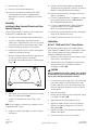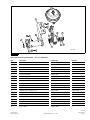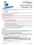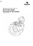
1
TP-0424
Revised 03-04
Camshaft Bracket and Slack Adjuster
Replacement on Meritor Steer Axles with
Cam Brakes
Applies to Peterbilt Vehicle Chassis
Identification Numbers
Service Parts
Instructions
817628 to 817727 with Q Plus™ LX500 Cam Brakes,
824511 to 824520 with Q Plus™ LX500 Cam Brakes and
821001 with Q Plus™ Cam Brakes
Meritor Service Kits MPS-4764 and MPS-4765
Revised
1TP-0424
Service03-04
Parts Instructions
Important Service Notes
Disassembly
Peterbilt and ArvinMeritor have determined that a brake and
steering component interference condition exists with certain
Q Plus™ and Q Plus™ LX500 steer axle cam brakes with
unhanded slack adjusters.
Remove the Camshaft Bracket and Slack
Adjuster Assembly
Only vehicles with the following chassis numbers are affected:
817628 to 817727 with Q Plus™ LX500 cam brakes, 824511 to
824520 with Q Plus™ LX500 cam brakes, 821001 with Q Plus™
cam brakes.
How to Obtain Additional Maintenance and
Service Information
Refer to Maintenance Manual MM-96173, Q Plus™ LX500 and
MX500 Cam Brakes; and Maintenance Manual 4, Cam Brakes.
To obtain these publications, call ArvinMeritor’s Customer Service
Center at 800-535-5560 or visit the Tech Library on our website
at arvinmeritor.com.
How to Obtain Parts
Service Kits MPS-4764 and MPS-4765
Service kits MPS-4764 and MPS-4765 are used to retrofit the brake
chamber brackets to eliminate the potential steering component
interference condition. Use kit MPS-4764 for vehicles with Q Plus™
LX500 series brakes. Use kit MPS-4765 for vehicles with Q Plus™
series brakes only. To obtain these kits, call ArvinMeritor’s
Commercial Vehicle Aftermarket at 888-725-9355.
ASBESTOS AND NON-ASBESTOS FIBERS
WARNING
Some brake linings contain asbestos fibers, a cancer and lung
disease hazard. Some brake linings contain non-asbestos
fibers, whose long-term effects to health are unknown. You
must use caution when you handle both asbestos and
non-asbestos materials.
WARNING
To prevent serious eye injury, always wear safe eye protection
when you perform vehicle maintenance or service.
Park the vehicle on a level surface. Block the wheels to
prevent the vehicle from moving. Support the vehicle with
safety stands. Do not work under a vehicle supported only by
jacks. Jacks can slip and fall over. Serious personal injury and
damage to components can result.
Use the following procedure to disassemble the camshaft bracket
and slack adjuster assembly. Perform this procedure carefully as the
camshaft will not be removed.
1.
Park the vehicle on a level surface. Block the wheels to prevent
the vehicle from moving.
2.
Raise the axle you are servicing and support it with safety
stands.
3.
Remove both clevis pins and retainer clips, or cotter pins, from
the clevis.
4.
Remove the air chamber from the bracket assembly.
5.
Remove the snap ring on the end of the camshaft.
6.
Remove the washers.
7.
Remove the slack adjuster.
8.
Remove the spacer washer.
9.
Remove the four bracket mounting fasteners.
9.
10. Remove the camshaft bracket assembly. Ensure that the
camshaft, bushing and seals are not damaged during
disassembly. Do not push the camshaft back into the brake
assembly.
Assembly
Install the new handed slack adjuster assembly obtained
separately. Refer to the maintenance and service procedures in
Maintenance Manual 4B, Automatic Slack Adjuster.
10. Install the new inboard, orange, slack adjuster seal. Refer to
Figure 2, item number 9.
11. For vehicles equipped with Q Plus™ LX500 brakes, assemble
the new spacing washers to achieve a 0.005-0.020-inch
(0.127-0.508 mm) maximum end play.
Installing the New Camshaft Bracket and Slack
Adjuster Assembly
12. For vehicles equipped with Q Plus™ brakes, assemble the
new spacing washers to achieve a 0.005-0.060-inch
(0.127-1.524 mm) maximum end play.
Use the following information to install the service kit components
for both Q Plus™ LX500 and Q Plus™ brakes.
13. Install the new camshaft snap ring to retain the slack adjuster.
Ensure that the camshaft rotates freely.
1.
Thoroughly clean the camshaft and spider mounting surfaces.
14. Perform the lubrication procedures in the next section.
2.
To prevent assembly damage, apply a liberal amount of
synthetic grease compound from the service kit to the seal lips
in the bracket assembly. Use kit part number 2297-X-7304.
Lubrication
3.
Install a new O-ring onto the flange end of the bracket.
4.
Carefully slide the bracket over the camshaft ensuring that the
camshaft is not pushed into the brake.
This lubrication procedure requires service kit MPS-4764 and
applies to Q Plus™ LX500 series brakes only. For Q Plus™ brakes,
refer to the brake lubrication procedures and guidelines in the
applicable Peterbilt brake service manual.
5.
Mount the camshaft bracket assembly to the spider with four
new capscrew fasteners. Tighten to 65-105 lb-ft
(88-142 N폷m) using the tightening sequence illustrated below.
Figure 1. @
Q Plus™ LX500 and Q Plus™ Series Brakes
1.
Install the new grease fitting into the cam assembly housing.
Refer to Figure 2, item number 20.
2.
Install the new pressure relief fitting into the cam assembly
housing. Refer to Figure 2, item number 6. Tighten to
45-180 lb-in (5-20 N폷m). @
Figure 1
1
4
CAUTION
Q Plus™ LX500 cam brakes require synthetic grease specified
by ArvinMeritor. Do not install standard brake grease or other
chassis grease. Damage to components can result.
3
3.
Use a manual grease gun to apply grease to the cam assembly
housing grease fitting. Use kit part number 2297-X-7304.
Continue to apply grease to the cam assembly housing until
the grease visibly purges through the pressure relief valve in
the camshaft tube.
2
4004389a
Figure 1
4.
Remove the grease fitting.
6.
Apply a liberal amount of anti-seize compound to the camshaft
splines. Use kit part number R580002.
5.
Install the new pipe plug into the brake camshaft tube. Tighten
to 45-180 lb-in (5-20 N폷m). @
7.
Install the new camshaft washer. Refer to Figure 2, item
number 7.
6.
Apply the lubrication interval tag supplied in the kit.
7.
Install the air chamber using the new clevis pins and clips.
Tighten the air chamber mounting bolts to 125-155 lb-ft
(169-210 N폷m). @
8.
Adjust the slack adjuster. Refer to Maintenance Manual 4B,
Automatic Slack Adjuster.
9.
Test the vehicle brakes to ensure correct operation.
NOTE: No slack adjuster seal replacement is required for vehicles
equipped with Q Plus™ brakes.
8.
Install the new outboard slack adjuster seal. Refer to Figure 2,
item number 8.
TP-0424
Revised 03-04
Page 2
Copyright ArvinMeritor, Inc., 2004
(16579/24240)
Printed in the USA
Figure 2
1
16
18
17
19
9
20
5
6
12
8
3
11
10
7
4004388b
4
Figure 2
Table A: MPS-4764 Kit Parts Description — Q Plus™ LX500 Brake
Item
Description
Part Number
Quantity
1
LH camshaft and chamber bracket
B87-3299Z6786
1
2
RH camshaft and chamber bracket
B87-3299A6787
1 (Not shown)
3
O-ring
1205-G-761
2
4
Capscrew
S-2810B-2
8
5
Pipe plug
1250-J-1284
2
6
Pressure relief fitting
1199-U-3947
2
7
Camshaft washer, thick
1299-H-4090
2
8
Outboard slack adjuster seal
1205-E-2527
2
9
Inboard slack adjuster seal, orange
1205-F-2528
2
10
Spacing washer, thin
1229-J-3130
4
11
Spacing washer, thick
1229-W-3117
4
12
Camshaft snap ring
1229-D-2942
2
13
Synthetic grease cartridge, 14 oz.
2297-X-7304
1 (Not shown)
14
Anti-seize compound tube, 0.5 oz.
R580002
4 (Not shown)
15
Instruction tag
2297-Z-7228
2 (Not shown)
16
Clevis pin
19X127
2
17
Clevis clip
2257C1173
2
18
Clevis pin
19X1116
2
19
Clevis clip
2257D1174
2
20
Grease fitting
1199-N-1860
2
(16579/24240)
Printed in the USA
Copyright ArvinMeritor, Inc., 2004
TP-0424
Revised 03-04
Page 3
Table B: MPS-4765 Kit Parts Description — Q Plus™ Brake
Item
Description
Part Number
Quantity
1
LH camshaft and chamber
B86-3299Z6786
1
2
RH camshaft and chamber
B86-3299A6787
1
3
O-ring
1205-G-761
2
4
Capscrew
S-2810B-2
8
5
Grease fitting
1199-N-1860
2
6
Camshaft washer, thick
1229-S-2697
2
7
Spacing washer, thin
1229-J-3130
4
8
Spacing washer, thick
1229-N-4590
4
9
Camshaft snap ring
1229-D-2942
2
10
Clevis pin
19X127
2
11
Clevis clip
2257C1173
2
12
Clevis pin
19X1116
2
13
Clevis clip
2257D1174
2
Meritor Heavy Vehicle Systems, LLC
2135 West Maple Road
Troy, MI 48084 USA
800-535-5560
arvinmeritor.com
Information contained in this publication was in effect at the time the publication was approved for printing and is subject to
change without notice or liability. Meritor Heavy Vehicle Systems, LLC, reserves the right to revise the information presented or
discontinue the production of parts described at any time.
Copyright 2004
ArvinMeritor, Inc.
All Rights Reserved
Printed in the USA
TP-0424
Revised 03-04
(16579/24240)