1
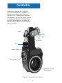
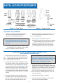
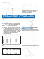
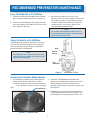
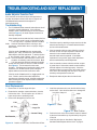
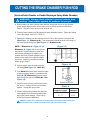
L30006
Rev. 3/02
CSI Midland/Gunite
Automatic Brake Adjuster
Service Manual
TABLE OF CONTENTS
Overview ............................................................................3
Installation Procedures ......................................................4
Brake Adjustment ..............................................................6
Preventative Maintenance ................................................7
Testing Adjuster Function and Boot Replacement ............8
Cutting the Brake Chamber Push Rods ............................9
Service Practices: Points and Precautions ......................10
Lining/Drum Replacement Procedures ............................10
WARNING
AS WITH ALL PRODUCTS, CLOSE ATTENTION SHOULD BE
GIVEN TO ALL INSTRUCTIONS INCORPORATED IN THIS
MANUAL, IN PARTICULAR THE NOTES AND WARNINGS
WHICH ARE HIGHLIGHTED.
FAILURE TO STRICTLY FOLLOW THESE INSTRUCTIONS
MAY RESULT IN THE UNIT PERFORMING IN AN
UNSATISFACTORY MANNER AND RESULT IN INADEQUATE
BRAKING ABILITY OR DRAGGING BRAKES. THESE
CONDITIONS COULD MAKE OPERATION OF THE VEHICLE
EXTREMELY HAZARDOUS.
ATTENTION
When installing or replacing an Automatic Brake Adjuster, a
new clevis must be installed. Refer to the Haldex Master
Catalog for clevis selection.
2
OVERVIEW
Haldex offers a complete line of unhanded
automatic brake adjusters for installation on
steering, drive and trailer axles. The space
required for the CSI Midland/Gunite automatic
brake adjuster is similar to that which is required
for manual brake adjusters. CSI Midland/Gunite
automatic brake adjusters do not require any
external brackets, adapters or special mounting
holes for installation.
Link
Clevis
1/2” or 5/8”
Pin
1/4” Pin
Boot
Grease Fitting
Hex Extension
Drilled & Grooved
Worm Wheel
Figure 1 - Automatic Brake Adjuster
3
INSTALLATION PROCEDURES
Jam Nut
Clevis
Collar
Lock
Clevis
Gage
3/4”
Standard Standard
Collar Nut Threaded Collar Lock
Extended Extended
Clevis
Clevis
Threaded Collar Lock
1-1/4” Nut
Clevis
Clevis
Collar Lock
Standard length clevises
Extended clevises
Nut and Clevis
can be used for either
truck or trailer applications. should be used for trailer
applications only.
Camshaft
End
Figure 3 - Gage Location
Figure 2 - Clevis Types
Preparation for Installation
1.
2.
If the axle is equipped with spring brake chambers,
manually cage the spring brakes following the
manufacturer’s recommended procedures.
Remove the existing clevis and brake adjuster. Do not
discard the existing mounting hardware. Do not remove the clevis jam nut.
NOTE
When caging the spring brakes, always be sure
to block the vehicle wheels to prevent unwanted
movement.
4.
3.
Check the operating condition of the foundation brakes,
including drums, shoe and linings, cams, bushings,
rollers, etc. Replace or repair as necessary.
Refer to Figure 2 and determine if your CSI
Midland/Gunite automatic brake adjusters are equipped
with the threaded clevis or the collar lock clevis
(extended or standard length). Refer to the correct
installation procedure for the style of clevis used on
your CSI Midland/Gunite automatic brake adjusters.
Installation of the CSI Midland/Gunite Threaded Clevis
and Extended Threaded Clevis
1. Apply anti-seize compound to the air chamber push
rod.
Install the new clevis on the air chamber push rod
in the same location as the clevis which was removed.
Do not tighten the jam nut at this time.
2.
3.
NOTE
On axles equipped with spring brake chambers,
be sure the chambers are fully caged before cutting
the push rod. If the spring brakes are not fully
caged, the push rod can be cut too short.
Using the gage supplied, insert the large pin through
the large hole at the top of the gage and into the clevis.
Center the proper 1/4” hole at the bottom of the gage
over the center hole of the camshaft (Figure 3). Adjust
the clevis until all of the 1/4” pin hole is visible in the
notch area of the gage. Double check the installation
by making sure the 1/4” hole at the bottom of the gage
is still centered on the camshaft when the 1/4” pin hole
is visible.
4.
If the push rod fails to come within 1/8” of full
engagement with the clevis boss threads, install a long
push rod and cut to length. Extended Clevis: On trailer
applications, an extended clevis can be used instead of
replacing the push rod. However, you must have at
least 1/2” of thread engagement inside the clevis. If
you have less than 1/2” thread engagement, a new push
rod must be installed.
If the push rod threads protrude through the clevis
boss more than 1/16”, remove the clevis and cut the
push rod to length. The push rod must not be more
than 1/8” short of being flush with the clevis boss.
4
5.
Apply anti-seize compound to camshaft.
6.
Install the automatic brake adjuster on the camshaft
using the original mounting hardware.
Aligning the Automatic Brake Adjuster with the Clevis
7.
Apply anti-seize compound to clevis pins.
10. Tighten the jam nut against the clevis.
8.
Rotate the hex extension clockwise until the 1/4” hole in
the brake link aligns with the 1/4” hole in the clevis.
Install the clevis pin and the cotter pin.
9.
NOTE
Failure to tighten the jam nut will allow the air
chamber push rod to rotate in the clevis and
change the installed position of the brake,
preventing proper automatic adjuster function.
Tap the clevis upward or downward until the large hole in
the brake arm aligns with the large hole in the clevis.
Install the clevis pin and the cotter pin.
11. Refer to installation check on page 6.
NOTE
Tapping the clevis downward moves the link into
the brake housing. If alignment is not achieved
when the link bottoms out, it indicates improper
clevis installation. Downward movement of the
link requires only light tapping.
Installation of the CSI Midland/Gunite Collar Lock Clevis and
Extended Collar Lock Clevis
1.
Apply anti-seize compound to the end of the air chamber
push rod. Install the 1-1/4” nut on the air chamber push
rod. Thread the 3/4” collar onto the push rod.
2.
Connect the clevis to the 1-1/4” nut.
3.
Using the gage supplied, insert the large pin through the
large hole at the top of the gage and into the clevis.
Center the proper 1/4” hole at the bottom of the gage
over the center hole of the camshaft (Figure 3). Adjust
the clevis by rotating the 3/4” collar until all of the 1/4” pin
hole is visible in the notch area of the gage. Double
check the installation by making sure the 1/4” hole at the
bottom of the gage is still centered on the camshaft when
the 1/4” pin hole is visible.
4.
5.
Apply anti-seize compound to camshaft.
6.
Install the automatic brake adjuster on the camshaft
using the original mounting hardware.
Aligning the Automatic Brake Adjuster
with the Clevis
7.
Apply anti-seize compound to the clevis pins.
8.
Rotate the hex extension clockwise until the 1/4” hole in
the brake link aligns with the 1/4” hole in the clevis.
Install the link pin and the cotter pin.
9.
If the push rod threads protrude through the clevis boss
more than 1/8”, mark the push rod, remove the clevis and
cut the push rod to length. The push rod must have at
least full thread engagement inside the 3/4” collar nut. If
you do not have full thread engagement the push rod
must be replaced. If you replace the push rod you must
cut the new push rod to the proper length. Refer to
cutting push rod section on page 9.
On trailer applications, an extended clevis can be used
instead of replacing the push rod. However, you must
still have full thread engagement inside the collar nut. If you
have less than full thread engagement, a new push rod
must be installed. If you replace the push rod you must
cut the new push rod to the proper length. Refer to
cutting push rod section on page 9.
Tap the clevis upward or downward until the large hole in
the brake arm aligns with the large hole in the clevis.
Install the clevis pin and the cotter pin.
10. Tighten 1-1/4” nut to 40-50 ft-lbs of torque.
NOTE
Tapping the clevis downward moves the link into
the brake housing. If alignment is not achieved
when the link bottoms out, it indicates improper
clevis installation. Downward movement of the
link requires only light tapping.
11. Tighten the 15/16” jam nut against the 1-1/4” nut.
Tighten to 40-50 ft-lbs of torque.
NOTE
Failure to tighten the jam nut will allow the air
chamber push rod to rotate in the clevis and
change the installed position of the brake adjuster,
preventing proper automatic adjuster function.
NOTE
On axles equipped with spring brake chambers, be
sure the chambers are fully caged before cutting
the push rod. If the spring brakes are not fully
caged, the push rod can be cut too short.
12. Refer to installation check on page 6.
5
Installation Check
1.
2. Build-up vehicle air pressure. If the axle in question
has parking brakes, be sure they’re released. Using
template, recheck for proper clevis setting. If incorrect,
readjust per instructions under installation procedures.
Manually uncage the spring brakes.
3.
Fully apply the brakes and allow the air chamber to
travel its maximum stroke. Clearance must exist
between the brake adjuster and all adjacent chassis
components such as axle housing, suspension
brackets, etc. Release the brakes.
Figure 4 - Gage Location
BRAKE ADJUSTMENT AFTER INSTALLATION
Adjust the brakes as follows:
1.
Rotate the hex extension clockwise until the brake linings
contact the brake drum. Back off the automatic brake
adjuster by rotating the hex counterclockwise 1/2 turn.
A
B
2.
Backing off the brake adjuster will require more than 2530 ft-lbs of torque. When backing off the brake
adjuster,
a ratcheting sound will be heard.
3.
Figure 5 - Measuring Maximum Stroke
Using a ruler, measure the distance from the face of the
air chamber to the center of the large pin in the clevis (A)
(See Figure 5). Make an 85 psi brake application and
allow the chamber push rod to travel its maximum stroke.
Measure to the center of the large pin (B). The difference
between (A) and (B) is the push rod stroke. Check the
following chart for proper maximum stroke after
adjustment of the brakes.
Measuring the Free Stroke
4.
Free stroke is the amount of movement of the brake
adjuster arm required to move the brake shoes against
the drum. With brakes released, measure from the face
of the chamber to the center of the clevis pin. Use a
lever
to measure the movement of the brake adjuster until
the brake shoes contact the drum (Figure 6). The difference
between the released and applied measurements is the
free stroke. The free stroke should be 3/8” - 5/8”.
“STANDARD” CLAMP TYPE BRAKE CHAMBER DATA
Type
9
12
16
20
24
30
36*
Outside
Diameter
5-1/4
5-11/16
6-3/8
6-25/32
7-7/32
8-3/32
9
Rated
Stroke
1.75
1.75
2.25
2.25
2.25
2.50
3.00
Maximum stroke at which
brakes must be readjusted
1-3/8
1-3/8
1-3/4
1-3/4
1-3/4
2
2-1/4
If the free stroke is good, but the applied stroke is too
long, there is a problem with the foundation brake.
Check the foundation brake for missing or worn components
cracked brake drums, or improper lining to
drum contact.
If the free stroke is greater than the recommended
distance (3/8” - 5/8”), a function test of the automatic
brake adjuster should be performed (see page 8).
*Note: If type 36 chamber is used, brake adjuster length should be less
than 6”.
If the free stroke is less than 3/8”, a dragging brake can
occur. Check to see that the manual adjustment
procedure was followed correctly. Manually readjust the
brake following the “Brake Adjustment After Installation”
procedure on this page.
“LONG STROKE” CLAMP TYPE BRAKE CHAMBER DATA
Type
16
20
24
24*
30*
Outside
Diameter
6-3/8
6-25/32
7-7/32
7-7/32
8-3/32
Rated
Stroke
2.50
2.50
2.50
3.00
3.00
Maximum stroke at which
brakes must be readjusted
2
2
2
2-1/2
2-1/2
* Note: Identified by square air port bosses.
Figure 6 - Free Stroke
6
RECOMMENDED PREVENTATIVE MAINTENANCE
Every Three Months or 25,000 Miles
1.
Check the condition of the foundation brakes, including
drums, shoes and linings, cams, rollers, bushings, etc.
2.
Check for structural damage of the housing, worn clevis,
worn clevis bushings and condition of the boot for cuts or
tears. Replace if necessary.
3.
After allowing the brake drum to cool to room
temperature, check for correct chamber stroke following
the procedure on page 6. Due to different operating
conditions, chamber stroke tests may be necessary
at earlier intervals. See Charts on page 6 for the
recommended stroke measurements.
NOTE
An automatic brake adjuster should not have to
be manually adjusted except for initial installation
and at the time of brake reline.
Every Six Months or 50,000 Miles
CSI Midland/Gunite automatic brake adjusters are factory
lubricated and extensively sealed to protect against dirt,
water, salt and other corrosive elements. Nevertheless,
periodic lubrication is recommended.
Boot
Grease
Fitting
NOTE
Brake Adjusters with a grooved and drilled worm
wheel will not have a grease relief on the end cap
opposite the adjusting hex.
Hex
Extension
Figure 7 - Lubrication Points
Greasing the Automatic Brake Adjuster
1.
A grease fitting is provided to allow lubrication during
normal chassis servicing (See Figure 7). With a
conventional grease gun, lubricate until grease appears
on the camshaft or grease flows from the grease
relief.
Grease Relief
2.
The newest CSI Midland/Gunite automatic brake
adjusters are produced without a grease relief, forcing
lubricant through the drilled worm wheel onto the
camshaft. Previous designs incorporated a grease relief
(See Figure 8).
3.
Lubriplate Aero is the grease used in the manufacture
of CSI Midland/Gunite automatic brake adjusters. It is
recommended for use in temperatures as low as -40ºF.
Figure 8 - Grease Relief
7
TROUBLESHOOTING AND BOOT REPLACEMENT
Brake Adjuster Function Test
If the maximum stroke with an 85 psi brake application is
less than the distance shown in the chart on page 6, the
CSI Midland/Gunite automatic brake adjuster is
functioning properly.
Troubleshooting
1.
The CSI Midland/Gunite automatic brake adjuster should
not require manual readjustment. If the maximum
chamber stroke is within the range for the size chamber
used (See Figure 5), the brake adjuster should not be
manually readjusted.
Figure 9 - Brake Adjuster Function
If the chamber stroke exceeds the limit, measure the free
stroke. If the free stroke is good, but the applied stroke
is too long, there is a problem with the foundation
brake. Check the foundation brake for missing or worn
components, cracked brake drums or improper lining to
drum contact.
If the free stroke is greater than the recommended
distance (3/8” - 5/8”), a function test of the automatic
brake adjuster should be performed. To test the function
of the automatic brake adjuster, place a 7/16” box
wrench on the hex extension and rotate it 3/4 of a turn counter
clockwise. A ratcheting sound will be heard. Mark
the
7/16” hex extension with chalk and apply the brakes
several times and watch for the hex to rotate clockwise
(See Figure 9). The hex extension must rotate
clockwise. The adjustment is intentionally made in small
increments so it will take several cycles to bring the
adjuster within the stroke limit shown in the chart.
If the free stroke is less than 3/8”, a dragging brake can
occur. Check to see that the manual adjustment
procedure was followed correctly. Manually readjust the
brake following the “Brake Adjustment After Installation”
procedure on page 6.
2.
Check the torque by attaching a torque wrench to the hex
extension and turning it in a counterclockwise direction
and record the measurement.
3.
If the hex extension did not rotate clockwise or there is
less than 15 ft-lbs of torque required to rotate the hex
extension in the counterclockwise direction, the
automatic brake must be replaced. If immediate
replacement is not possible, proper brake adjustment
must be maintained by manual adjustment.
4.
If the hex extension rotates clockwise and has a torque
of greater than 15 ft-lbs when rotated counterclockwise,
the brake adjuster is functioning properly. Check the
foundation brake for proper function, worn quick connect
clevis, worn clevis bushings and clevis pins. Repair as
necessary and repeat the function test.
5.
Readjust the brake adjuster after the function test.
4.
Install the replacement boot over the link with the heavy
section down. Care should be taken not to damage the
boot with a sharp tool.
Link
Boot Replacement
1.
Remove the 1/4” and the large clevis pins.
2.
Rotate the hex extension counterclockwise to clear the
link from the clevis. This will require up to 45 ft-lbs of
torque and produce a ratcheting sound.
3.
Remove the damaged boot from the link.
Link
1/4” Pin
Groove
Boot
Insert
Clevis
Figure 11 - Boot
Large Pin
Boot
Figure 12 - Boot Position
Grease Fitting
5.
Position the boot on the link so that the bottom is retained
by the boot insert and the top is positioned by the groove
in the link.
6.
Install the clevis pins as described in “Aligning the
Automatic Brake Adjuster with the Clevis” on page 5.
Hex Extension
Figure 10 - Location of Clevis Pins, Hex Extensions & Boot
8
CUTTING THE BRAKE CHAMBER PUSH-ROD
(Service Brake Chamber or Double Diaphragm Spring Brake Chamber)
!
WARNING: Always chock wheels to prevent vehicle from
moving. Vent vehicle system air pressure to zero psi.
A. When preparing to install a spring brake chamber, ensure that the unit is fully released
(power spring caged) and the service brake push-rod is fully retracted to zero stroke
position. Thread the clevis jam nut onto the push-rod.
B. Place the brake chamber into the appropriate brake assembly bracket. Tighten the holding
nuts to the bracket studs (100 - 140 lb. ft.).
C. Measure the distance from the centerline of the S-Cam to the centerline of the push-rod
(See Figure 13 - Dimension A). This measurement should be equal to the length of
the brake adjuster being used (See Figure 14 - Dimension A).
Figure 13
NOTE: If Dimension A - Figure 13 and
Dimension A - Figure 14 are not identical,
the chamber mounting bracket is either bent
and must be straightened or replaced, the
chamber has been mounted improperly in the
bracket or the length of the adjuster installed
is incorrect. Make any necessary corrections
before going to Step D.
Figure 14
D. Using a square, mark the push-rod at the
90o setting (See Figure 13 - Mark #1).
E. From Mark #1 measure back toward the brake
chamber mounting surface in accordance with
Chart A (“X” Dimension), make a second
mark and cut the push-rod at Mark #2 - See
Figure 13).
F. Install the clevis onto the push-rod and secure
the jam nut. Connect the clevis to the brake
adjuster. Uncage the spring brake.
G. Release parking spring brakes and adjust the
brake adjuster to the shortest possible stroke
without the brakes dragging. Proper set-up
stroke should now be established.
!
BRAKE ADJUSTER
Chart A
Brake
Adjuster Length
5” - 5 1/2”
6” - 7”
“X”
Dimension
2 1/4”
2 1/2”
DANGER A spring brake or combination service/spring brake must be disarmed before disposal, or
forceful release of the compression spring may occur in the future without warning.
9
SERVICE PRACTICES: POINTS AND PRECAUTIONS
1.
Replace the automatic brake adjuster if it is
not functioning properly, as described under
“Brake Adjuster Function Test” on page 8.
2.
Replace the entire unit if damage is evident
on the automatic brake adjuster housing or
assembly.
3.
4. Never operate the vehicle with small 1/4”
pin missing from the clevis. The automatic
brake adjuster will not maintain proper
brake adjustment with either pin missing.
5. Never attempt to disassemble the
automatic brake adjuster. Factory setting
cannot be duplicated in the field. Instead,
replace the entire unit.
The unit must be replaced if less than 15
ft-lbs of torque exists when turning the
hex extension counterclockwise.
LINING/DRUM REPLACEMENT PROCEDURES
“STANDARD” CLAMP TYPE BRAKE CHAMBER DATA
Special attention must be given to proper maintenance
procedures of the automatic brake adjuster when you
change brake linings and/or brake drums.
1.
If the axle is equipped with spring brake chambers,
manually cage the spring brakes, following the
manufacturer’s recommended procedures.
2.
Using a 7/16” socket, rotate the hex extension
counterclockwise. You should have at least 15 ft-lbs
resistance and a ratcheting sound will be heard as the
hex extension is rotated.
3.
Only back off the adjusting hex enough to allow the
drum to clear the lining. Remove the brake drum. After
the brake drum has been removed, rotate the hex
extension clockwise until the cam turns over. This will
allow the brake rollers to be in the release position.
4.
Proceed with the lining change and/or brake drum
replacement.
5.
Rotate the hex extension clockwise until the brake
linings contact the brake drum.
6.
Back off the automatic brake adjuster by rotating the
hex extension 1/2 turn counterclockwise. A ratcheting
sound will be heard. This provides running clearance
between the lining and the drum.
7.
Using a ruler, measure the distance from the face of the
air chamber to the center of the large pin in the clevis
(A) (See Figure 15). Make an 85 psi brake application
and allow the air chamber to travel its maximum stroke.
Measure to the center of the large pin (B). The
difference between (A) and (B) is the push rod stroke.
Check the following charts for proper maximum stroke
after adjustment of the brakes.
8.
Manually uncage the spring brakes.
Type
9
12
16
20
24
30
36*
Outside
Diameter
5-1/4
5-11/16
6-3/8
6-25/32
7-7/32
8-3/32
9
Rated
Stroke
1.75
1.75
2.25
2.25
2.25
2.50
3.00
Maximum stroke at which
brakes must be readjusted
1-3/8
1-3/8
1-3/4
1-3/4
1-3/4
2
2-1/4
*Note: If type 36 chamber is used, brake adjuster length should be less
than 6”.
“LONG STROKE” CLAMP TYPE BRAKE CHAMBER DATA
Type
16
20
24
24*
30*
Outside
Diameter
6-3/8
6-25/32
7-7/32
7-7/32
8-3/32
Rated
Stroke
2.50
2.50
2.50
3.00
3.00
Maximum stroke at which
brakes must be readjusted
2
2
2
2-1/2
2-1/2
* Note: Identified by square air port bosses.
A
B
Figure 15 - Measuring Maximum Stroke
10
NOTES
11
HALDEX PRODUCTS DISTRIBUTED LOCALLY BY:
Brake Systems Division
World Headquarters
10930 N. Pomona Avenue
Kansas City, Missouri 64153-1297
Phone: (816) 891-2470
Fax: (816) 891-9447
www.haldexbrakes.com
Brake Systems Division
North American Sales & Service Organization
10707 N.W. Airworld Drive
Kansas City, Missouri 64153-1215
Phone: (816) 891-2470
Fax: (816) 880-9766
www.hbsna.com
REV. 3/02 1M ART L30006
Brake Systems Division
Haldex Limited
525 Southgate Drive Unit 1
Guelph, Ontario Canada N1G 3W6
Phone: (519) 826-7723
Fax: (519) 826-9497
www.hbsna.com


![Web Only [L31123W] Nov-2001](http://vs1.manualzilla.com/store/data/006261811_1-4af033c8ff7f86bb4ac91ee243d7e1f2-150x150.png)