1
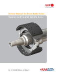
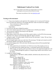
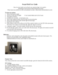
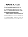
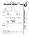
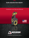
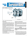
Gunite Slack Adjuster
Service Manual
C O R P O R A T I O N
Table of Contents
Overview . . . . . . . . . . . . . . . . . . . . . . . . . . . . . . . . . . . . . . . . . . . . . . . . . . . . . . . . . . . . . . . . . . . . . . . . . .3
Installation Procedures . . . . . . . . . . . . . . . . . . . . . . . . . . . . . . . . . . . . . . . . . . . . . . . . . . . . . . . . . . . . . . .4
Brake Adjustment . . . . . . . . . . . . . . . . . . . . . . . . . . . . . . . . . . . . . . . . . . . . . . . . . . . . . . . . . . . . . . . . . .10
Preventative Maintenance . . . . . . . . . . . . . . . . . . . . . . . . . . . . . . . . . . . . . . . . . . . . . . . . . . . . . . . . . . .11
Testing Adjuster Function and Boot Replacement . . . . . . . . . . . . . . . . . . . . . . . . . . . . . . . . . . . . . . . .12
Cutting Push Rods . . . . . . . . . . . . . . . . . . . . . . . . . . . . . . . . . . . . . . . . . . . . . . . . . . . . . . . . . . . . . . . . .13
Service Practices: Points and Precautions . . . . . . . . . . . . . . . . . . . . . . . . . . . . . . . . . . . . . . . . . . . . . . .13
Lining/Drum Replacement Procedure . . . . . . . . . . . . . . . . . . . . . . . . . . . . . . . . . . . . . . . . . . . . . . . . .14
WARNING
AS WITH ALL PRODUCTS, CLOSE ATTENTION SHOULD BE GIVEN TO
ALL INSTRUCTIONS INCORPORATED IN THIS MANUAL, IN PARTICULAR
THE NOTES AND WARNINGS WHICH ARE HIGHLIGHTED.
FAILURE TO STRICTLY FOLLOW THESE INSTRUCTIONS MAY RESULT IN
THE UNIT PERFORMING IN AN UNSATISFACTORY MANNER AND
RESULT IN INADEQUATE BRAKING ABILITY OR DRAGGING BRAKES.
THESE CONDITIONS COULD MAKE OPERATION OF THE VEHICLE
EXTREMELY HAZARDOUS.
ATTENTION
When installing or replacing a Gunite Slack Adjuster, a new clevis must
be installed. Refer to Gunite Parts Catalog GFL-ASA for clevis selection.
2
Overview
Gunite offers a complete line of unhanded slack adjusters
for installation on steering, drive and trailer axles. The space
required for the Gunite slack adjuster is similar to that
which is required for manual slack adjusters. Gunite slack
adjusters do not require any external brackets, adapters or
special mounting holes for installation.
THE BRAKES SHOULD BE IN GOOD OPERATING CONDITION AND STATE OF REPAIR WHEN GUNITE SLACK
ADJUSTERS ARE INSTALLED. NO SLACK ADJUSTER CAN
COMPENSATE FOR PROBLEMS AND DEFICIENCIES IN THE
FOUNDATION BRAKING SYSTEM.
Popular spline and arm length combinations allow them to
be used to replace most other slack adjusters. However,
brands should not be mixed on the same axle.
Link
Clevis
1/2" or 5/8" Pin
1/4" Pin
Boot
Grease Fitting
Hex Extension
Drilled & Grooved
Worm Wheel
Figure 1 – Gunite Slack Adjuster
3
Installation Procedures
Collar
Lock
Clevis
3/4"
Hex Nut
1-1/4"
Collar Nut
Standard
Threaded
Clevis
Standard
Collar Lock
Clevis
Standard length clevises
can be used for either truck
or trailer applications.
Collar Lock
Nut and Clevis
Extended
Threaded
Clevis
Extended
Collar Lock
Clevis
Extended clevises
should be used for trailer
applications only.
Figure 2 – Clevis Types
Preparation for Installation
1. If the axle is equipped with spring brake chambers, manually cage the spring brakes following the manufacturer’s
recommended procedures.
NOTE
When caging the spring brakes, always be sure to
block the vehicle wheels to prevent unwanted
movement.
3. Remove the existing clevis and slack adjuster. Do not discard the existing mounting hardware. Do not remove the
clevis jam nut.
4. Refer to figure 2 and determine if your Gunite automatic slack adjusters are equipped with the threaded
clevis or the collar lock clevis (extended or standard
length). Refer to the correct installation procedure for
the style of clevis used on your Gunite slack adjusters.
2. Check the operating condition of the foundation brakes,
including drums, shoe and linings, cams, bushings,
rollers, etc. Replace or repair as necessary.
Installation Procedures for Gunite Slack Adjusters Using a Collar Lock Clevis
2
1
Block the vehicle’s wheels. If the axle is equipped
with spring brakes, manually cage the brakes
following the manufacturer’s recommended
procedures.
4
Remove the existing clevis and slack adjuster. Keep
the existing mounting hardware. Do not remove the
clevis jam nut.
6
3
Apply anti-seize to the chamber push rod threads
before installing the new clevis. Also apply anti-seize
to the camshaft at this time.
Using the hex extension and a wrench, adjust the
slack so that the collar nut aligns with the threaded
area of the clevis.
4
7
When installing a Gunite slack adjuster with a collar
lock clevis, place the 1-1/4" collar nut on the push
rod against the 15/16" jam nut. Next thread the 3/4"
hex nut onto the push rod.
Before attaching the 1-1/4" collar nut to the clevis,
check to make sure the threaded push rod is fully
engaged in the 3/4" hex nut. If the push rod
does not have full engagement, a new push rod
must be installed and cut to length. Refer to the
section on cutting a new pushrod to length in
the service manual.
5
The push rod may extend up to 1/16" past the clevis
opening. If the push rod extends more than 1/16"
past the clevis opening, mark the push rod and
remove the clevis to allow the push rod to be cut
to the proper length.
Install the slack onto the camshaft using the original
mounting hardware.
Gunite slack adjusters using the collar lock clevis
are available with either standard or extended clevis
designs depending on the application. On trailer
applications, an extended clevis can be used instead
of replacing the push rod. However, you must still
have full thread engagement inside the hex nut.
If you have less than full thread engagement, a new
push rod must be installed. If you replace the push
rod, you must cut the new push rod to the proper
length. Refer to the section on cutting a new push
rod to length in the service manual. Do not use
extended clevis on tractor applications.
NOTE
On axles equipped with spring brake chambers, be sure
the chambers are fully caged before cutting the push
rod. If the spring brakes are not fully caged, the push rod
can be cut too short.
5
8
11
After threading the 1-1/4" collar nut onto the clevis
housing, place the template over the large and small
clevis pins as shown above.
Once the 1-1/4" collar nut has been properly tightened to the clevis, tighten the 15/16" jam nut
against the collar lock nut using 40 to 50 ft lbs
of torque.
9
NOTE
Failure to tighten the jam nut will allow the air chamber
push rod to rotate in the clevis and change the installed
position of the slack, preventing proper automatic
adjuster function.
12
Align the slack by adjusting the 3/4" hex nut on the
push rod until the appropriate centering hole on the
template aligns with the center hole on the camshaft. The template is provided with centering holes
for 5, 5.5, 6 and 6.5 inch slacks.
10
Fully apply the brakes and allow the chamber push
rod to travel its maximum stroke. Clearance must
exist between the slack adjuster and all adjacent
chassis components. Release the brakes.
Using a torque wrench, tighten the 1-1/4" collar nut
to the clevis using 40 to 50 ft lbs of torque.
6
13
Pre-adjust the brakes by rotating the hex extension
clockwise until the brake lining contacts the brake
drum. Back the slack adjuster off by rotating the hex
counterclockwise 1/2 turn. Backing off a new slack
adjuster may require up to 50 ft lbs of torque. A
ratcheting sound will be heard when backing the
slack off.
After completing this step, uncage the spring brake.
Refer to page 10 for proper brake adjustment
procedures.
Installation Procedures for Gunite Slack Adjusters Using a Threaded Clevis
1
3
Block the vehicle’s wheels. If the axle is equipped
with spring brakes, manually cage the brakes following the manufacturer’s recommended procedures.
Apply anti-seize to the chamber push rod threads
before installing the new clevis.
2
4
Remove the existing clevis and slack adjuster. Keep
the existing mounting hardware. Do not remove the
clevis jam nut.
7
When installing a Gunite slack adjuster with a
threaded clevis, install the new clevis on the push
rod in the same location as the clevis which was
removed. Do not tighten the jam nut at this time.
It is also important to make sure that the push rod
is not too short for proper installation. To do this,
check to make sure that the push rod is not more
than 1/8" short of being flush with the clevis opening
on a standard clevis (5/8" on an extended clevis). If
the threaded push rod is more than 1/8" from being
flush with the clevis opening on a standard clevis
(5/8" on an extended clevis) it must be removed,
a new push rod must be installed and
cut to the proper length.
5
Follow instructions in the service manual for cutting
a push rod to length.
Once the clevis has been installed on the threaded
push rod, install both the large and small clevis pins.
Now position the installation template over both the
large and small clevis pins.
NOTE
On axles equipped with spring brake chambers, be sure
the chambers are fully caged before cutting the push
rod. If the spring brakes are not fully caged, the push rod
can be cut too short.
6
8
Align the clevis on the threaded push rod until the
appropriate centering hole on the template aligns
with the center hole on the camshaft. The template
is provided with centering holes for 5, 5.5, 6 and 6.5
inch slacks.
Tighten the jam nut against the clevis housing using
40 to 50 ft lbs of torque. If you do not tighten the
jam nut now, it will allow the clevis to rotate freely
and change the position of the clevis resulting in an
improper installation.
Once the clevis has been properly adjusted, remove
the template and the two clevis pins.
7
NOTE
Failure to tighten the jam nut will allow the air chamber
push rod to rotate in the clevis and change the installed
position of the slack, preventing proper automatic
adjuster function.
Inspect the clevis installation to make sure that the
threaded push rod extends no more than 1/16" past
the end of the opening of the clevis in the clevis
housing. If the push rod extends more than 1/16"
past the clevis housing, the clevis must be removed
and the push rod cut to the proper length.
8
9
11
Apply anti-seize compound to the camshaft, install
the slack adjuster and adjust the position of the slack
using the hex extension. Adjust the slack until the
holes in the slack housing align properly with the
corresponding holes in the clevis.
Fully apply the brakes and allow the chamber push
rod to travel its maximum stroke. Clearance must
exist between the slack adjuster and all adjacent
chassis components. Release the brakes.
10
12
Once the clevis is properly aligned with the slack
adjuster, insert both the large and small clevis pins
and secure with the cotter pins supplied.
Pre-adjust the brakes by rotating the hex extension
clockwise until the brake lining contacts the brake
drum. Back the slack adjuster off by rotating the
hex counterclockwise 1/2 turn. Backing off a new
slack adjuster may require up to 50 ft lbs of torque.
A ratcheting sound will be heard when backing the
slack off.
After completing this step, uncage the spring brake.
Refer to page 10 for proper brake adjustment
procedures.
9
Brake Adjustment After Installation
Adjust the brakes as follows:
1. Rotate the hex extension clockwise until the brake linings
contact the brake drum. Back off the slack adjuster by
rotating the hex counterclockwise 1/2 turn.
2. Backing off the slack will require approximately 25 to 30
ft lbs of torque. When backing off the slack adjuster,
a ratcheting sound will be heard.
3. Using a ruler, measure the distance from the face of the
air chamber to the center of the large pin in the clevis
(A) (see fig. 4). Make an 85 psi brake application and
allow the chamber push rod to travel its maximum
stroke. Measure to the center of the large pin (B). The
difference between (A) and (B) is the push rod stroke.
Check the following chart for proper maximum stroke
after adjustment of the brakes.
Figure 4 – Measuring Maximum Stroke
Measuring the Free Stroke
“STANDARD” CLAMP TYPE BRAKE CHAMBER DATA
Type
Outside
Diameter
Rated
Stroke
Maximum stroke at which
brakes must be readjusted
9
5-1/4
1.75
1-3/8
12
5-11/16
1.75
1-3/8
16
6-3/8
2.25
1-3/4
20
6-25/32
2.25
1-3/4
24
7-7/32
2.25
1-3/4
30
8-3/32
2.50
2
36*
9
3.00
2-1/4
4. Free stroke is the amount of movement of the slack
adjuster required to move the brake shoes against the
drum. With brakes released, measure from the face of
the chamber to the center of the clevis pin. Use a ruler
to measure the movement of the slack adjuster until
the brake shoes contact the drum (fig. 5). The difference
between the released and applied measurements is the
free stroke. The free stroke should be 3/8" to 5/8".
If the free stroke is good, but the applied stroke is too
long, there is a problem with the foundation brake. Check
the foundation brake for missing or worn components,
cracked brake drums, or improper lining to drum contact.
* Note: If type 36 chamber is used, slack length should be less
than 6".
If the free stroke is greater than the recommended distance (3/8" to 5/8"), a function test of the slack adjuster
should be performed (see page 12).
“LONG STROKE” CLAMP TYPE BRAKE CHAMBER DATA
If the free stroke is less than 3/8", a dragging brake
can occur. Check to see that the manual adjustment
procedure was followed correctly. Manually readjust the
brake following the “Brake Adjustment After Installation”
procedure on this page.
Outside
Diameter
Rated
Stroke
Maximum stroke at which
brakes must be readjusted
16
6-3/8
2.50
2
20
6-25/32
2.50
2
Type
24
7-7/32
2.50
2
24*
7-7/32
3.00
2-1/2
30*
8-3/32
3.00
2-1/2
* Note: Identified by square air port bosses.
Figure 5 – Free Stroke
10
Recommended Preventative Maintenance
Every Three Months or 25,000 Miles
1. Check the condition of the foundation brakes, including
drums, shoes and linings, cams, rollers, bushings, etc.
2. Check for structural damage of the housing, worn clevis,
worn clevis bushings and condition of the boot for cuts
or tears. Replace if necessary.
3. After allowing the brake drum to cool to room temperature, check for correct chamber stroke following the
procedure on page 10. Due to different operating
conditions, chamber stroke tests may be necessary at
earlier intervals. See Charts on page 10 for the recommended stroke measurements.
NOTE
An automatic slack adjuster should not have to
be manually adjusted except for initial installation
and at the time of brake reline.
Every Six Months or 50,000 Miles
Gunite slack adjusters are factory lubricated and extensively
sealed to protect against dirt, water, salt and other
corrosive elements. Nevertheless, periodic lubrication
is recommended.
Boot
NOTE
Slack Adjusters with a grooved and drilled worm wheel
will not have a grease relief on the end cap opposite
the adjusting hex.
Grease
Fitting
Hex
Extension
Figure 6 – Lubrication Points
Greasing the Slack Adjuster
1. A grease fitting is provided to allow lubrication during
normal chassis servicing (see fig. 6). With a conventional
grease gun, lubricate until grease appears on the
camshaft, or grease flows from the grease relief.
Grease Relief
Figure 7 – Grease Relief
11
2. The newest Gunite slack adjusters are produced without
a grease relief, forcing lubricant through the drilled worm
wheel onto the camshaft. Previous designs incorporated
a grease relief ( see fig. 7).
3. Lubriplate Aero is the grease used in the manufacture
of Gunite slack adjusters. It is recommended for use in
temperatures as low as -40 degrees F.
Trouble-shooting and Boot Replacement
Slack Adjuster Function Test
If the maximum stroke, with an 85 psi brake application is
less than the distance shown in the chart on page 10, the
Gunite slack adjuster is functioning properly.
Trouble-shooting
1. The Gunite slack adjuster should not require manual readjustment. If the maximum chamber stroke is
within the range for the size chamber used (see fig. 4),
the slack adjuster should not be manually readjusted.
If the chamber stroke exceeds the limit, measure the free
stroke. If the free stroke is good, but the applied stroke
is too long, there is a problem with the foundation
brake. Check the foundation brake for missing or worn
components, cracked brake drums, or improper lining
to drum contact.
If the free stroke is greater than the recommended
distance (3/8" to 5/8"), a function test of the slack
adjuster should be performed. To test the function of
the slack adjuster, place a 7/16" box wrench on the hex
extension and rotate it 3/4 of a turn counterclockwise.
A ratcheting sound will be heard. Mark the 7/16" hex
extension with chalk and apply the brakes several times
and watch for the hex to rotate clockwise (see fig. 8).
The hex extension must rotate clockwise. The adjustment
is intentionally made in small increments so it will take
several cycles to bring the adjuster within the stroke limit
shown in the chart.
If the free stroke is less than 3/8", a dragging brake can
occur. Check to see that the manual adjustment procedure was followed correctly. Manually readjust the brake
following the “Brake Adjustment After Installation”
procedure on page 10.
Figure 8 – Adjuster Function
2. Check the torque by attaching a torque wrench to the
hex extension and turning it in a counterclockwise direction and record the measurement.
3. If the hex extension did not rotate clockwise during
brake application or there is less than 15 ft lbs of torque
required to rotate the hex extension in the counterclockwise direction, the slack adjuster must be replaced. If
immediate replacement is not possible, proper brake
adjustment must be maintained by manual adjustment.
4. If the hex extension rotates clockwise and has a
torque of greater than 15 ft lbs when rotated
counterclockwise, the slack is functioning properly.
Check the foundation brake for proper function, worn
cam bushing, pins and rollers, broken springs, worn
quick connect clevis, worn clevis bushings and clevis
pins. Repair as necessary and repeat the function test.
5. Readjust the brake after the function test.
Boot Replacement
1. Remove the 1/4" and the large clevis pins.
2. Rotate the hex extension counterclockwise to clear the
link from the clevis. This could require up to 50 ft lbs of
torque and produce a ratcheting sound.
4. Install the replacement boot over the link with the heavy
section down. Care should be taken not to damage the
boot with a sharp tool.
Link
3. Remove the damaged boot from the link.
Groove
Boot
Insert
Link
Clevis
1/4" Pin
Large Pin
Figure 10 – Boot
Boot
Grease Fitting
Figure 11 – Boot Position
Hex Extension
5. Position the boot on the link so that the bottom is
retained by the boot insert and the top is positioned
by the groove in the link.
Figure 9 – Location of Clevis Pins, Hex Extension & Boot
6. Install the clevis pins
12
Cutting Universal Chamber Push Rods
Cutting the Push Rod
1. Install the brake chamber in the proper mounting holes
of the chamber bracket for the slack adjuster length
required.
2. If the axle is equipped with spring brake chamber, manually cage the spring brakes following the manufacturer’s
recommended procedures. The chamber must be in the
fully released position.
3. Using a square, mark the universal push rod at the 90
degree position when the square edge is centered in the
end of the S-Cam (see fig. 12). Make sure the push rod
is centered in the chamber and not cocked before marking the push rod.
4. From the 90 degree mark, measure back toward the air
chamber the proper “X” distance from the following
chart. Mark the push rod at the “X” dimension. Cut the
push rod at this mark (see fig. 13). The clevis is now
ready to install on the push rod.
Slack
Adjuster Length
“X”
Dimension
5" – 5-1/2"
2-1/4"
6" – 6-1/2"
2-1/2"
90°
Cut
Here
S-Cam
Spline
S-Cam
Spline
Figure 13 – Cutting the Push Rod
Figure 12 – Marking the Push Rod
Service Practices: Points and Precautions
1. Replace the slack adjuster if it is not functioning
properly, as described under “Slack Adjuster
Function Test” on page 12.
4. Never operate the vehicle with small 1/4"
pin missing from the clevis. The slack adjuster
will not maintain proper brake adjustment
with either pin missing. (ref. ASA drwg.)
2. Replace the entire unit if damage is evident on
the slack housing or assembly.
5. Never attempt to disassemble the slack
adjuster. Factory setting cannot be duplicated
in the field. Instead, replace the entire unit.
3. The unit must be replaced if less than
15 ft lb of torque exists when turning the
hex extension counterclockwise. Refer to
the test as described under “Troubleshooting.” (ref. ASA drwg.)
13
Procedure for brake lining and/or drum replacement
Special attention must be given to following proper
maintenance procedures when changing linings and/or
drums on a vehicle equipped with Gunite slack adjusters.
Following these procedures will ensure that the slack
adjuster is functioning correctly before returning the vehicle
to service.
1. Block the vehicle’s wheels.
5. After the brake drum has been removed; rotate the hex
extension clockwise until the cam turns over. This will
allow the brake rollers to be in the release position.
2. If the vehicle is equipped with spring brake chambers,
manually cage the spring brakes following the
manufacturer’s recommended procedures.
6. Proceed with the lining change and/or brake drum
replacement.
3. Using a 7/16" wrench or socket, rotate the hex extension counterclockwise. You should have at least 15 ft lbs
resistance and a ratcheting sound will be heard as the
hex extension is rotated.
7. Once the linings have been replaced and the brake
drum installed, rotate the hex extension clockwise until
the brake linings contact the brake drum.
4. Only back off the adjusting hex enough to allow the
drum to clear the lining. Remove the brake drum.
14
8. Back-off the slack adjuster by rotating the hex extension
1/2 turn counterclockwise. A ratcheting sound will be
heard. This will provide running clearance between the
lining and the drums braking surface.
“STANDARD” CLAMP TYPE BRAKE CHAMBER DATA
Outside
Diameter
Rated
Stroke
Maximum stroke at which
brakes must be readjusted
9
5-1/4
1.75
1-3/8
12
5-11/16
1.75
1-3/8
1-3/4
Type
16
6-3/8
2.25
20
6-25/32
2.25
1-3/4
24
7-7/32
2.25
1-3/4
30
8-3/32
2.50
2
36*
9
3.00
2-1/4
* Note: If type 36 chamber is used, slack length should be less
than 6".
9. Using a ruler, measure the distance from the face of
the air chamber to the center of the large pin in the
clevis (A) (see fig. 14).
“LONG STROKE” CLAMP TYPE BRAKE CHAMBER DATA
Type
Outside
Diameter
Rated
Stroke
Maximum stroke at which
brakes must be readjusted
2
16
6-3/8
2.50
20
6-25/32
2.50
2
24
7-7/32
2.50
2
24*
7-7/32
3.00
2-1/2
30*
8-3/32
3.00
2-1/2
* Note: Identified by square air port bosses.
10. Make an 85 psi brake application and allow the air
chamber to travel its maximum stroke. Measure the
distance between the face of the air chamber and the
center of the large clevis pin (B) (see fig. 14). The
difference between the (A) measurement and the (B)
measurement is the push rod stroke. Check the charts
located on page10 for the proper maximum stroke after
adjustment of the brakes.
Figure 14 – Measuring Maximum Stroke
11. Manually uncage the spring brakes before returning the
vehicle to service.
If you need additional service manuals or installation gages, contact
Gunite Corporation at the address listed on the back of this manual.
15
Distributed By:
C O R P O R A T I O N
Fleet Line Products
302 Peoples Ave. ■ Rockford, IL 61104-7092
Phone (815) 964-3301 ■ Toll-Free (800) 677-3786 ■ Fax (815) 965-9197
www.gunite.com
Form ASA 100-99 Supercedes ASA 100-97