1
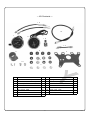
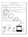
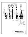
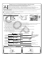
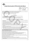
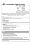
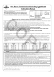
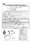
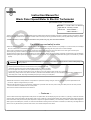
Instruction Manual for
CO
Black Panel Speed Meter & Electric Tachometer
(for inverted front fork / φ30 front fork)
Item No.
:09−01−1951
Applicable to :Monkey / Gorilla
Frame Nos. :Z50J-2000001∼
:AB27-1000001 ∼
Thank you for purchasing one of our TAKEGAWA’s products. Please strictly follow the following instructions in installing and using the products. Before
fitting the products, please be sure to check the contents of the kit. Should you have any questions about the products, please kindly contact your dealer.
◎ Please note that, in some cases, the illustrations and photos may vary from the actual hardware.
PY
For proper use and safety’s sake
◎This kit is designed for exclusive use in vehicles equipped with TAKEGAWA’s inverted front fork kit, a top bridge for aφ30 inner tube, and a headlight
kit for an inverted fork kit. Please take note that this product cannot be used along with other parts such as a stock headlight.
◎ This product is designed for exclusive use in 12V Monkey. Please take note that this cannot be used in 6V or other types of mortorcycles.
◎ The spark plug must be a resistor plug. Otherwise the tachometer doesn’t display correctly.
◎ Always start the engine with the battery installed on the vehicle. Besides, please use a quality battery. Otherwise, the tachometer may be damaged.
◎Always use stock ignition-system parts. If a high-tension cord, plug cap,and / or ignition coil are replaced with other types, a tachometer may not work
properly.
The following show the envisioned possibility of injuries to human bodies and property loss as a result of disregarding the
CAUTION following cautions.
・Work only when the engine and the muffler are cool below 35 degrees C. (Otherwise, you will burn yourself.)
・Prepare right tools for the work, and do the work in the proper and right way.
(Otherwise, improper work could cause breakage of parts or injuries to yourself.)
・Be sure to tighten each bolt and nut to the specified torque using a torque wrench.
・This kit does not come with a speed warning light. So always try to drive carefully, being careful not to overspeed.
・Before riding, always check every section for slack in parts like screws. Besides, when you notice something abnormal with your motorcycle
while riding down a road, stop riding immediately and park your motorcyle in a safe place.
◎ Please be informed that, mainly because of improvement in performance, design changes, and cost increase, the product specifications and prices are subject to change without prior notice.
◎ We shall be held free from any kind of warranty whatsoever of products other than this product if the glitch takes place on the other products than this one after the installation and use of this product.
◎ This manual should be retained for future reference.
∼ Features ∼
This is a meter kit with newly designed black meter panels. The speed meter, with the display range of up to 160 km / h (100 mph), includes an odometer
and a trip meter, and the tachometer, with the display range of up to 14,000 rpm, is a highly-precise electric type. Both the speed meter and the tachometer
have a translucent meter panel and two panel lamps each to improve the nighttime viewability. The meter body is made of stainless steel designed to
attain high level of durability and, moreover, is rubber-mounted aimed at reducing the level of vibration. Furthermore, a meter stay is so designed that a
switch cover may be attached to protect an LED neutral, turn-indicator lamps and main switch.
-1-
Nov./05/’
08
∼ Kit Contents ∼
CO
1
10
11
14
2
8
15
PY
13
4
3
6
12
7
9
No.
Parts Name
Qty
No.
Parts Name
Qty
1
Speed meter assembly
1
9
Tapping screw 4X12
2
2
Electric tachometer assembly
1
10
LED neutral indicator lamp
1
3
Meter stay
1
11
LED turn indicator lamp
1
4
Cushion rubber
4
12
Button-head screw 8X10
2
5
Collar 8.5 mm
4
13
Sub cord (black)
1
6
Plain washer 5X18
8
14
Speed meter cable
1
7
Hex nut 5 mm
4
15
Electro tap
1
8
Combination switch cover
1
※Parts No. 5 is included in the No. 4 cushion rubber.
-2-
Nov./05/’
08
∼ Installation Procedures ∼
1. Fix four cushion rubbers onto the meter stay, and insert four 8.5mm collars to each of four cushion rubbers.
2. Insert a plain washer (5x18) to a threaded portion on the electric tachometer, and install the tachometer onto the right side of the meter stay.
Attach a 5x18 plain washer and hex nut from the back side of the cushion rubber, and tighten them to the specified torque.
Torque : 5 N・m (0.5 kgf・m)
CO
3. Insert a plain washer (5x18) to a threaded portion on the speed meter, and install the speed meter onto the meter stay.
As you did with a tachometer, attach a plain washer and hex nut from the back side of the cushion rubber, and tighten them to the specified torque.
Torque : 5 N・m (0.5 kgf・m)
4. Fix an LED neutral indicator lamp and a turn indicator lamp to the meter stay. Then attach spring washers from the back side of the stay and tighten nuts.
5. Install a combination switch cover with tapping screws so its notch will be located obliquely downward to the right. Remove a combination switch from
the stock light case, and press the switch into the switch cover until it’s locked with claws.
(Pull out a combination switch from the light case by pressing two claws inwards with a fine-tip screwdriver or the like.)
6. Place the meter stay in between the headlight stay on the back side of the top bridge and the top bridge, and tighten them all together with button-head
screws.
Torque : 12 N・m (1.2 kgf・m)
7.CONNECTION: Wiring in the head light housing
Black = Brown (Tachometer)
Green = Green (Tachometer)
Black/ Yellow (Taco meter) = Ignition coil.
Red (Speed meter) = Brown (Tachometer).
Black = Green.
PY
8.CONNECTION: LED Neutral indicator lump:
Black (LED) = Light green/Red. Then connect to the Black (wiring).
9.LED Turn signal indicator light:
Red (indicator) = Black (sub wire), Then connect to the Grey (wiring) with quick connector (as shown)
10. Connect the speed meter cable. Start the engine and check whether each lamp lights and the tachometer operates normally. If there is nothing abnormal, run the vehicle in a safe place at low speed to check the operation of the speed meter.
How to connect electro tap
①
②
Stopper
Meter Assembly Diagram
③
Joining
terminal
Vehicle’s
wire- harness
gray cord
① Set the position of the ② Fold back the tap at the
③ Then, fold back the
cords, placing them in the
relative conduits on the arrow mark (⇒ ) to
temporarily fix the cords.
section with a joining
terminal. Securely hold it Spring washer
(Supplied with a meter)
Hex nut
(Supplied with a meter)
Plain washer
Collar
Meter stay
Cushion rubber
down with a plier or the like
until it is completely locked.
Plain washer
Hex nut
LED turn-indicator-lamp black
cord
electro tap. (Place the black cord in the conduit until the cord tip hits the Connection
completed
stopper.)
-3-
Nov./05/’
08
∼ Wiring Diagram ∼
Tachometer
Speed meter
CO
B
/ G Br B
Y
Ignition coil
B
G /
Y
G
G
LED neutral lamp
LED turn lamp
B R
R B
BR
Electro tap
Sub cord (B)
PY
B G Y Gr Lb O
B
Lg
/
R
B
B
B
6P
B G Y Gr Lb O
Blinker swith 6P coupler
B ・・・BLACK
Y ・・・YELLOW
G ・・・GREEN
O ・・・ORANGE
R ・・・RED
Br・・・BROWN
Lb・・・LIGHT BLUE
Lg・・・LIGHT GREEN
Gr・・・GRAY
Co.,Ltd.
3-5-16 Nishikiorihigashi Tondabayashi Osaka Japan
TEL : 81-721-25-1357 FAX : 81-721-24-5059
URL : http://www.takegawa.co.jp
-4-
Nov./05/’
08
Please be sure to do the following before using this meter.
NOTE
○ Use this meter with a battery installed. (Otherwise, the tachometer itself will break down.)
○ Run this meter only after checking that the AC regulator is functioning all right.
(Otherwise, the tachometer may breakdown.) * Please see the service manual for the inspection method.
○ Be sure to use a stock plug cord and plug cap. (Otherwise, the tachometer may malfunction in displaying or break down.)
○ Be sure to always use a resistor-type spark plug. (Otherwise, the tachometer may malfunction in displaying.)
CO
◎Inspection of AC regulator:
○Warm up the engine, and stop it.
Connect an AC voltmeter to an AC regulator connector (+ to the white and yellow cord, and - to the green cord), and start the engine.
NOTE: Be careful of the wire short circuit or have the wires touch each other.
Control voltage: 13 ~ 15 V/5,000 rpm
○If the controlled voltage is not within the specified value, check the connector for loose. Measure the voltage again, and if the controlled voltage is not
within the limit even after this procedure, change the AC regulator.
Green terminal
―Probe
○
Examples:
Denso
NGK
Heat value
Peak voltage adaptor
Digital tester
Heat value
U24FSR-U
CR8HSA
Resistortype
Resistortype
◎Check the tachometer for malfunction:
White / yellow terminal ○
+ Probe
○ The needle jumps across the dial.
① The needle jumps across the dial when speed is accelerated.
* In case the resistive resistor spark plug is not used, change the spark plug to the resistor type.
* In case the spark plug smolders because the spark plug heat value is not as per the above figure, or because the fuel is not controlled correctly,
correct the heat value of the smoldering spark plug, or replace the plug with the thoroughly-cleaned spark plug or with a new one.
* In case the un-designated plug cord or plug cap is used, change each of them with the stock one.
* When the voltage is under voltage, recharge the battery or replace it with a new one.
And in case the battery is functioning normally but the voltage is under voltage, check your motorcycle for malfunction.
② In case the rotating meter does not operate when the engine is started:
* In case the battery is removed, install back the battery.
* In case the voltage is under-voltage, recharge the battery or replace it with a new one.
And in case the battery is functioning normally but the voltage is under voltage, check your motorcycle for malfunction.
* In case the non-stock generator is in use, change the parts with those for the stock generator.
③ In case the needle position has changed:
* In case the needle moves from the new position. (Changed the position of the needle with a magnet.)
Malfunction condition
○
PY
Inspect
Cause
Test the battery for leakage
leaking
Not leaking
Start the engine, and measure
the control voltage between
the battery terminals.
Voltage does not rise above
the battery voltage
Normal level
・Poor connection of wire harness
・Contact failure of the connector
・Battery failure
Measure the resistance value of AC
Far off from the standard value
but within the normal level
Normal level
・Defective lamp coil
Measure the control voltage of DC
power supply.
Far off from the standard value
but within the normal level
・Contact failure of a coupler
・Breaking of wires
Normal level
・Defective DC power supply
◎Correction of needle position
When the needle has scaled out because of overturning, correct the
needle position referring to the figures below. Place the magnet close
to the needle as shown below.
As shown in the figure below, move the magnet slowly until the needle
points to ‘O’.
Magnet
Needle
Needle
Magnet
‘O’ point
-5-
Nov./05/’
08