1
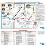
TROUBLESHOOTING EC-17 ANTILOCK SYSTEMS WITH OPTIONAL TRACTION CONTROL
INSTRUCTIONS
ANTILOCK / TRACTION
CONTROLLER
(Ref. SD-13-4788)
TRACTION SERVICE Enable / Disable
(LOCATED IN DASH AREA)
ABS
When Servicing DRIVELINE
Disable TRACTION (Switch OFF)
DASH
LAMPS
WHEEL SPIN
M-22
view
EC-17
DIAGNOSTIC
DISPLAY
Ty Wrap
Exciter
Ring
START UP: When power is applied the Antilock and
Traction dash warning lamps will illuminate while the
electronic Control Unit (ECU) is performing a Self Check,
and “Chuff” test. The ABS and Traction Control modulators
will be energized during the Chuff test. At the completion of
the Chuff test the ABS and Traction dash lamps will flash
and extinguish. It is recommended during the initial start up
that the brakes be applied to audibly hear the modulators
exhaust during the “Chuff’ test.
SERVICE NEEDED: When an issue is detected at start up,
the dash lights will flash and remain illuminated at the
completion of the chuff test. When a dynamic wheel speed
issue is detected the dash lamps will illuminate as early as
10 mph, indicating a wheel speed issue. The dash lamps
notify the driver that all or part of the ABS function has been
disengaged and standard air braking is in effect. The ECU will
automatically reset most intermittent codes (self healing). In
most instances, if the intermittent code has occurred more
than five times the issue will be latched and require a
magnetic reset. The area of concern will always be identified
in the diagnostic display.
TRACTION FUNCTION: The ECU monitors wheel spin.
When a spin condition exist, the traction dash lamp will blink
continuously indicating the traction control system is active.
IF SERVICING THE VEHICLE DRIVE LINE, TRACTION
SERVICE ENABLE / DISABLE SWITCH MUST BE DISABLED.
(The traction dash lamp will be illuminated)
RESET: The ECU can be magnetically reset by momentarily
holding a magnet against the RESET area on the controller.
SELF CONFIGURING: During self configuring the ECU will
automatically determine the number of sensors and if
electronic engine equipped. The ECU will also determine
if the vehicle is traction equipped ONLY if the traction switch
is toggled prior to magnetically Self Configuring.
Holding a magnet against the RESET area for 30 seconds
completes Self Configuring.
Hub
ANTILOCK
MODULATOR
ASSEMBLY
(Ref. SD-13-4793)
Source
Exhaust B
A
VEHICLE
ENGINE MODULE
Drum
1587 DIAGNOSTIC
CONNECTOR
Hold
C
MODULATOR
HOLD TO SOURCE:
C–B
READ 3.5 TO 5 OHMS
EXHAUST TO SOURCE:
EXHAUST TO HOLD:
A–B
A–C
READ 3.5 TO 5 OHMS
READ 7 TO 10 OHMS
SOURCE TO GROUND:
B–
NO CONTINUITY
Mounting
TYPICAL
WHEEL SPEED
REAR AXLE
SENSOR-CONNECTOR
Connector
M-22
view
Right
Angle
Sensor
Exciter
Ring
Straight
Sensor
Clip
TYPICAL
FRONT
AXLE
Resistance
Across Pins:
1500-2500 Ohms
(Ref. SD-13-4754)
BW1982 © Honeywell 2/2000 Printed in U.S.A.
Visit: www.bendix.com