1
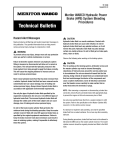
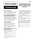
TP-99102
Rev 01-04
User’s Manual
TOOLBOX
SOFTWARE
TM
▲▲▲▲▲▲▲▲
▲
MER ▲
▲▲
I
X
O
B
L
TOO
▲▲▲▲▲
▲
▲▲▲
▲
▲▲ O
C
▲▲▲▲▲
▲
▲
▲
▲▲
▲
W
A
▲ OR
B
T
Diagnostic and On-Screen Service Instructions For:
왘 Pneumatic
왘 Hydraulic
E
R
A
W
SOFT
K N O W
ABS (D and E Versions)
왘 Trailer ABS (Easy-StopTM and Enhanced Easy-StopTM
with PLC)
T
TO
A
WH
ABS (HABS)
왘 Hydraulic Power Brake (HPB)
왘 Electronic Leveling Module (ELM) for Tractors
왘 Electronic Leveling Module (ELM) for Trailers
▲▲▲▲▲▲▲
▲▲
▲
▲
▲▲
D
YO U
N EE
tool.bk.book Page -1 Wednesday, April 14, 2004 12:22 PM
Table of Contents
Table of Contents
Introduction . . . . . . . . . . . . . . . . . . . . . . . . . . . . . . . . . . . . . . . . . . . . . . . . . . . . . . . . 1
System Requirements . . . . . . . . . . . . . . . . . . . . . . . . . . . . . . . . . . . . . . . . . . . . . . . . . . . . 2
Installation . . . . . . . . . . . . . . . . . . . . . . . . . . . . . . . . . . . . . . . . . . . . . . . . . . . . . . . . . . . . .3
Starting TOOLBOXTM Software . . . . . . . . . . . . . . . . . . . . . . . . . . . . . . . . . . . . . . . . . . . . . 3
Main Menu . . . . . . . . . . . . . . . . . . . . . . . . . . . . . . . . . . . . . . . . . . . . . . . . . . . . . . . . . . . . .4
Main Menu . . . . . . . . . . . . . . . . . . . . . . . . . . . . . . . . . . . . . . . . . . . . . . . . . . . . . . . . . 5
System Setup . . . . . . . . . . . . . . . . . . . . . . . . . . . . . . . . . . . . . . . . . . . . . . . . . . . . . . . . . . . 5
Language . . . . . . . . . . . . . . . . . . . . . . . . . . . . . . . . . . . . . . . . . . . . . . . . . . . . . . . . . . . . . . 5
Select ECU . . . . . . . . . . . . . . . . . . . . . . . . . . . . . . . . . . . . . . . . . . . . . . . . . . . . . . . . . . . . .6
COM Port . . . . . . . . . . . . . . . . . . . . . . . . . . . . . . . . . . . . . . . . . . . . . . . . . . . . . . . . . . . . . . . 6
Vendor . . . . . . . . . . . . . . . . . . . . . . . . . . . . . . . . . . . . . . . . . . . . . . . . . . . . . . . . . . . . . . . . . 7
Protocol . . . . . . . . . . . . . . . . . . . . . . . . . . . . . . . . . . . . . . . . . . . . . . . . . . . . . . . . . . . . . . . . 7
Device . . . . . . . . . . . . . . . . . . . . . . . . . . . . . . . . . . . . . . . . . . . . . . . . . . . . . . . . . . . . . . . . . 8
Help . . . . . . . . . . . . . . . . . . . . . . . . . . . . . . . . . . . . . . . . . . . . . . . . . . . . . . . . . . . . . . . . . . .8
System Information . . . . . . . . . . . . . . . . . . . . . . . . . . . . . . . . . . . . . . . . . . . . . . . . . . . . . . 8
Update Applications (Versions 5.0 and Higher) . . . . . . . . . . . . . . . . . . . . . . . . . . . . . . . . 9
About . . . . . . . . . . . . . . . . . . . . . . . . . . . . . . . . . . . . . . . . . . . . . . . . . . . . . . . . . . . . . . . . . . 9
Tractor ABS . . . . . . . . . . . . . . . . . . . . . . . . . . . . . . . . . . . . . . . . . . . . . . . . . . . . . . . 11
Reference Material . . . . . . . . . . . . . . . . . . . . . . . . . . . . . . . . . . . . . . . . . . . . . . . . . . . . . .11
Main Screen . . . . . . . . . . . . . . . . . . . . . . . . . . . . . . . . . . . . . . . . . . . . . . . . . . . . . . . . . . . 11
Restart Exit Help . . . . . . . . . . . . . . . . . . . . . . . . . . . . . . . . . . . . . . . . . . . . . . . . . . . . . . . . 12
Tractor ECU . . . . . . . . . . . . . . . . . . . . . . . . . . . . . . . . . . . . . . . . . . . . . . . . . . . . . . . . . . . .12
Display . . . . . . . . . . . . . . . . . . . . . . . . . . . . . . . . . . . . . . . . . . . . . . . . . . . . . . . . . . . . . . . . 12
Faults . . . . . . . . . . . . . . . . . . . . . . . . . . . . . . . . . . . . . . . . . . . . . . . . . . . . . . . . . . . . . . . . 13
Wheel Speed . . . . . . . . . . . . . . . . . . . . . . . . . . . . . . . . . . . . . . . . . . . . . . . . . . . . . . . . . . . 14
Memorized Data (E Version ABS Only) . . . . . . . . . . . . . . . . . . . . . . . . . . . . . . . . . . . . . 15
RSC Data (E Version ABS Only) . . . . . . . . . . . . . . . . . . . . . . . . . . . . . . . . . . . . . . . . . . . 16
Component Tests . . . . . . . . . . . . . . . . . . . . . . . . . . . . . . . . . . . . . . . . . . . . . . . . . . . . . . . 17
Valves . . . . . . . . . . . . . . . . . . . . . . . . . . . . . . . . . . . . . . . . . . . . . . . . . . . . . . . . . . . . . . . . 17
RSC Trailer Valve (E Version ABS Only) . . . . . . . . . . . . . . . . . . . . . . . . . . . . . . . . . . . . . 18
Lamps . . . . . . . . . . . . . . . . . . . . . . . . . . . . . . . . . . . . . . . . . . . . . . . . . . . . . . . . . . . . . . . . 19
Relay . . . . . . . . . . . . . . . . . . . . . . . . . . . . . . . . . . . . . . . . . . . . . . . . . . . . . . . . . . . . . . . . .19
Engine Data Link . . . . . . . . . . . . . . . . . . . . . . . . . . . . . . . . . . . . . . . . . . . . . . . . . . . . . . . 20
Disable ATC . . . . . . . . . . . . . . . . . . . . . . . . . . . . . . . . . . . . . . . . . . . . . . . . . . . . . . . . . . . 20
Enable ATC . . . . . . . . . . . . . . . . . . . . . . . . . . . . . . . . . . . . . . . . . . . . . . . . . . . . . . . . . . . .21
Reset Memorized . . . . . . . . . . . . . . . . . . . . . . . . . . . . . . . . . . . . . . . . . . . . . . . . . . . . . . . 21
Trailer ABS . . . . . . . . . . . . . . . . . . . . . . . . . . . . . . . . . . . . . . . . . . . . . . . . . . . . . . . . 23
Reference Material . . . . . . . . . . . . . . . . . . . . . . . . . . . . . . . . . . . . . . . . . . . . . . . . . . . . . .23
Main Screen . . . . . . . . . . . . . . . . . . . . . . . . . . . . . . . . . . . . . . . . . . . . . . . . . . . . . . . . . . . 23
Restart Exit Help . . . . . . . . . . . . . . . . . . . . . . . . . . . . . . . . . . . . . . . . . . . . . . . . . . . . . . . . 24
Trailer ECU . . . . . . . . . . . . . . . . . . . . . . . . . . . . . . . . . . . . . . . . . . . . . . . . . . . . . . . . . . . .24
Language Restart . . . . . . . . . . . . . . . . . . . . . . . . . . . . . . . . . . . . . . . . . . . . . . . . . . . . . . . 24
Manual Setup . . . . . . . . . . . . . . . . . . . . . . . . . . . . . . . . . . . . . . . . . . . . . . . . . . . . . . . . . . 25
Print . . . . . . . . . . . . . . . . . . . . . . . . . . . . . . . . . . . . . . . . . . . . . . . . . . . . . . . . . . . . . . . . . .25
Save . . . . . . . . . . . . . . . . . . . . . . . . . . . . . . . . . . . . . . . . . . . . . . . . . . . . . . . . . . . . . . . . . .25
Display . . . . . . . . . . . . . . . . . . . . . . . . . . . . . . . . . . . . . . . . . . . . . . . . . . . . . . . . . . . . . . . . 27
Faults . . . . . . . . . . . . . . . . . . . . . . . . . . . . . . . . . . . . . . . . . . . . . . . . . . . . . . . . . . . . . . . . . 27
Fault Information . . . . . . . . . . . . . . . . . . . . . . . . . . . . . . . . . . . . . . . . . . . . . . . . . . . . . . . 27
Component Tests . . . . . . . . . . . . . . . . . . . . . . . . . . . . . . . . . . . . . . . . . . . . . . . . . . . . . . . 28
Valve and Lamp Activation . . . . . . . . . . . . . . . . . . . . . . . . . . . . . . . . . . . . . . . . . . . . . . .28
Valves . . . . . . . . . . . . . . . . . . . . . . . . . . . . . . . . . . . . . . . . . . . . . . . . . . . . . . . . . . . . . . . . 29
Lamp . . . . . . . . . . . . . . . . . . . . . . . . . . . . . . . . . . . . . . . . . . . . . . . . . . . . . . . . . . . . . . . . .29
Sensors . . . . . . . . . . . . . . . . . . . . . . . . . . . . . . . . . . . . . . . . . . . . . . . . . . . . . . . . . . . . . . . 30
Sensor Orientation Test (For Enhanced Easy-StopTM Only) . . . . . . . . . . . . . . . . . . . . .32
Modify . . . . . . . . . . . . . . . . . . . . . . . . . . . . . . . . . . . . . . . . . . . . . . . . . . . . . . . . . . . . . . . . 33
Service Information . . . . . . . . . . . . . . . . . . . . . . . . . . . . . . . . . . . . . . . . . . . . . . . . . . . . .33
Tire Calibration . . . . . . . . . . . . . . . . . . . . . . . . . . . . . . . . . . . . . . . . . . . . . . . . . . . . . . . . . 34
Reconfigure . . . . . . . . . . . . . . . . . . . . . . . . . . . . . . . . . . . . . . . . . . . . . . . . . . . . . . . . . . . .35
Notebook . . . . . . . . . . . . . . . . . . . . . . . . . . . . . . . . . . . . . . . . . . . . . . . . . . . . . . . . . . . . . 35
Lift Axle . . . . . . . . . . . . . . . . . . . . . . . . . . . . . . . . . . . . . . . . . . . . . . . . . . . . . . . . . . . . . . . 36
Plant Location/OEM . . . . . . . . . . . . . . . . . . . . . . . . . . . . . . . . . . . . . . . . . . . . . . . . . . . . .36
Revised 01-04
TP-99102
Page -1
tool.bk.book Page 0 Wednesday, April 14, 2004 12:22 PM
Table of Contents
Hydraulic ABS . . . . . . . . . . . . . . . . . . . . . . . . . . . . . . . . . . . . . . . . . . . . . . . . . . . . . 37
Reference Material . . . . . . . . . . . . . . . . . . . . . . . . . . . . . . . . . . . . . . . . . . . . . . . . . . . . . . 37
Main Screen . . . . . . . . . . . . . . . . . . . . . . . . . . . . . . . . . . . . . . . . . . . . . . . . . . . . . . . . . . . 37
Restart Exit Help . . . . . . . . . . . . . . . . . . . . . . . . . . . . . . . . . . . . . . . . . . . . . . . . . . . . . . . . 38
Tractor ECU . . . . . . . . . . . . . . . . . . . . . . . . . . . . . . . . . . . . . . . . . . . . . . . . . . . . . . . . . . . 39
Language Restart . . . . . . . . . . . . . . . . . . . . . . . . . . . . . . . . . . . . . . . . . . . . . . . . . . . . . . . 39
Exit . . . . . . . . . . . . . . . . . . . . . . . . . . . . . . . . . . . . . . . . . . . . . . . . . . . . . . . . . . . . . . . . . . 39
Display . . . . . . . . . . . . . . . . . . . . . . . . . . . . . . . . . . . . . . . . . . . . . . . . . . . . . . . . . . . . . . . 39
Faults . . . . . . . . . . . . . . . . . . . . . . . . . . . . . . . . . . . . . . . . . . . . . . . . . . . . . . . . . . . . . . . . . 40
Component Tests . . . . . . . . . . . . . . . . . . . . . . . . . . . . . . . . . . . . . . . . . . . . . . . . . . . . . . . 41
Valves . . . . . . . . . . . . . . . . . . . . . . . . . . . . . . . . . . . . . . . . . . . . . . . . . . . . . . . . . . . . . . . . 41
Actuate Outputs . . . . . . . . . . . . . . . . . . . . . . . . . . . . . . . . . . . . . . . . . . . . . . . . . . . . . . . . 42
Reset Memorized . . . . . . . . . . . . . . . . . . . . . . . . . . . . . . . . . . . . . . . . . . . . . . . . . . . . . . . 43
End of Line . . . . . . . . . . . . . . . . . . . . . . . . . . . . . . . . . . . . . . . . . . . . . . . . . . . . . . . . . . . . 43
Hydraulic Power Brake (HPB) . . . . . . . . . . . . . . . . . . . . . . . . . . . . . . . . . . . . . . . 48
Technical Assistance . . . . . . . . . . . . . . . . . . . . . . . . . . . . . . . . . . . . . . . . . . . . . . . . . . . . 48
Main Screen . . . . . . . . . . . . . . . . . . . . . . . . . . . . . . . . . . . . . . . . . . . . . . . . . . . . . . . . . . . 48
Restart Exit Help . . . . . . . . . . . . . . . . . . . . . . . . . . . . . . . . . . . . . . . . . . . . . . . . . . . . . . . . 49
Tractor ECU . . . . . . . . . . . . . . . . . . . . . . . . . . . . . . . . . . . . . . . . . . . . . . . . . . . . . . . . . . . 49
Language . . . . . . . . . . . . . . . . . . . . . . . . . . . . . . . . . . . . . . . . . . . . . . . . . . . . . . . . . . . . . 49
Restart . . . . . . . . . . . . . . . . . . . . . . . . . . . . . . . . . . . . . . . . . . . . . . . . . . . . . . . . . . . . . . . . 49
Exit . . . . . . . . . . . . . . . . . . . . . . . . . . . . . . . . . . . . . . . . . . . . . . . . . . . . . . . . . . . . . . . . . . 49
Display . . . . . . . . . . . . . . . . . . . . . . . . . . . . . . . . . . . . . . . . . . . . . . . . . . . . . . . . . . . . . . . 49
Faults . . . . . . . . . . . . . . . . . . . . . . . . . . . . . . . . . . . . . . . . . . . . . . . . . . . . . . . . . . . . . . . . . 50
Wheel Speed . . . . . . . . . . . . . . . . . . . . . . . . . . . . . . . . . . . . . . . . . . . . . . . . . . . . . . . . . . 51
Counters . . . . . . . . . . . . . . . . . . . . . . . . . . . . . . . . . . . . . . . . . . . . . . . . . . . . . . . . . . . . . . 51
Component Tests . . . . . . . . . . . . . . . . . . . . . . . . . . . . . . . . . . . . . . . . . . . . . . . . . . . . . . . 52
Valves . . . . . . . . . . . . . . . . . . . . . . . . . . . . . . . . . . . . . . . . . . . . . . . . . . . . . . . . . . . . . . . . 52
Lamps . . . . . . . . . . . . . . . . . . . . . . . . . . . . . . . . . . . . . . . . . . . . . . . . . . . . . . . . . . . . . . . . 53
Parking Brake . . . . . . . . . . . . . . . . . . . . . . . . . . . . . . . . . . . . . . . . . . . . . . . . . . . . . . . . . . 53
Relay . . . . . . . . . . . . . . . . . . . . . . . . . . . . . . . . . . . . . . . . . . . . . . . . . . . . . . . . . . . . . . . . . 54
Engine Data Link . . . . . . . . . . . . . . . . . . . . . . . . . . . . . . . . . . . . . . . . . . . . . . . . . . . . . . . 54
Disable ATC . . . . . . . . . . . . . . . . . . . . . . . . . . . . . . . . . . . . . . . . . . . . . . . . . . . . . . . . . . . 55
Enable ATC . . . . . . . . . . . . . . . . . . . . . . . . . . . . . . . . . . . . . . . . . . . . . . . . . . . . . . . . . . . . 55
Miscellaneous Outputs . . . . . . . . . . . . . . . . . . . . . . . . . . . . . . . . . . . . . . . . . . . . . . . . . . 56
Reset Memorized (For Systems Equipped with a Retarder Relay) . . . . . . . . . . . . . . . 57
ELM for Tractors . . . . . . . . . . . . . . . . . . . . . . . . . . . . . . . . . . . . . . . . . . . . . . . . . . . 58
Reference Material . . . . . . . . . . . . . . . . . . . . . . . . . . . . . . . . . . . . . . . . . . . . . . . . . . . . . . 58
Computer to Vehicle . . . . . . . . . . . . . . . . . . . . . . . . . . . . . . . . . . . . . . . . . . . . . . . . . . . . 58
Main Screen . . . . . . . . . . . . . . . . . . . . . . . . . . . . . . . . . . . . . . . . . . . . . . . . . . . . . . . . . . . 58
Restart Exit Help . . . . . . . . . . . . . . . . . . . . . . . . . . . . . . . . . . . . . . . . . . . . . . . . . . . . . . . . 59
ELM . . . . . . . . . . . . . . . . . . . . . . . . . . . . . . . . . . . . . . . . . . . . . . . . . . . . . . . . . . . . . . . . . . 59
Display . . . . . . . . . . . . . . . . . . . . . . . . . . . . . . . . . . . . . . . . . . . . . . . . . . . . . . . . . . . . . . . 59
Faults . . . . . . . . . . . . . . . . . . . . . . . . . . . . . . . . . . . . . . . . . . . . . . . . . . . . . . . . . . . . . . . . . 59
Components . . . . . . . . . . . . . . . . . . . . . . . . . . . . . . . . . . . . . . . . . . . . . . . . . . . . . . . . . . . 60
Modify . . . . . . . . . . . . . . . . . . . . . . . . . . . . . . . . . . . . . . . . . . . . . . . . . . . . . . . . . . . . . . . . 61
Calibrate . . . . . . . . . . . . . . . . . . . . . . . . . . . . . . . . . . . . . . . . . . . . . . . . . . . . . . . . . . . . . . 61
ELM for Trailers . . . . . . . . . . . . . . . . . . . . . . . . . . . . . . . . . . . . . . . . . . . . . . . . . . . . 63
Reference Material . . . . . . . . . . . . . . . . . . . . . . . . . . . . . . . . . . . . . . . . . . . . . . . . . . . . . . 63
Computer to Vehicle . . . . . . . . . . . . . . . . . . . . . . . . . . . . . . . . . . . . . . . . . . . . . . . . . . . . 63
Main Screen . . . . . . . . . . . . . . . . . . . . . . . . . . . . . . . . . . . . . . . . . . . . . . . . . . . . . . . . . . . 63
Restart Exit Help . . . . . . . . . . . . . . . . . . . . . . . . . . . . . . . . . . . . . . . . . . . . . . . . . . . . . . . . 64
ELM . . . . . . . . . . . . . . . . . . . . . . . . . . . . . . . . . . . . . . . . . . . . . . . . . . . . . . . . . . . . . . . . . . 64
Display . . . . . . . . . . . . . . . . . . . . . . . . . . . . . . . . . . . . . . . . . . . . . . . . . . . . . . . . . . . . . . . 64
Faults . . . . . . . . . . . . . . . . . . . . . . . . . . . . . . . . . . . . . . . . . . . . . . . . . . . . . . . . . . . . . . . . . 64
Components . . . . . . . . . . . . . . . . . . . . . . . . . . . . . . . . . . . . . . . . . . . . . . . . . . . . . . . . . . . 65
Modify . . . . . . . . . . . . . . . . . . . . . . . . . . . . . . . . . . . . . . . . . . . . . . . . . . . . . . . . . . . . . . . . 66
Calibrate . . . . . . . . . . . . . . . . . . . . . . . . . . . . . . . . . . . . . . . . . . . . . . . . . . . . . . . . . . . . . . 67
Appendix . . . . . . . . . . . . . . . . . . . . . . . . . . . . . . . . . . . . . . . . . . . . . . . . . . . . . . . . . . 69
Driver Select Information . . . . . . . . . . . . . . . . . . . . . . . . . . . . . . . . . . . . . . . . . . . . . . . . . 69
Communication Drivers . . . . . . . . . . . . . . . . . . . . . . . . . . . . . . . . . . . . . . . . . . . . . . . . . 69
Adapter Box . . . . . . . . . . . . . . . . . . . . . . . . . . . . . . . . . . . . . . . . . . . . . . . . . . . . . . . . . . . 69
Selecting an Adapter Box in TOOLBOXTM . . . . . . . . . . . . . . . . . . . . . . . . . . . . . . . . . . . 69
Connecting the Adapter Box . . . . . . . . . . . . . . . . . . . . . . . . . . . . . . . . . . . . . . . . . . . . . . 70
Fault Information Sheet . . . . . . . . . . . . . . . . . . . . . . . . . . . . . . . . . . . . . . . . . . . . . . . . . . 70
TOOLBOXTM Technical Support . . . . . . . . . . . . . . . . . . . . . . . . . . . . . . . . . . . . . . . . . 71
System Information (Versions 5.0 and Higher) . . . . . . . . . . . . . . . . . . . . . . . . . . . . . . . 71
About . . . . . . . . . . . . . . . . . . . . . . . . . . . . . . . . . . . . . . . . . . . . . . . . . . . . . . . . . . . . . . . . 72
tool.bk.book Page 1 Wednesday, April 14, 2004 12:22 PM
Introduction
Introduction
Meritor WABCO TOOLBOXTM Software is a
PC-based diagnostics program that runs in
Windows® 98, Me, NT, 2000 or XPa.
TOOLBOXTM Software provides PC diagnostic
capabilities for Meritor WABCO tractor and
trailer pneumatic ABS, hydraulic ABS and the
electronic leveling module (ELM) for both
tractor and trailer. The program provides four
basic functions:
• Displays both constant (e.g., ECU number)
and changing (e.g., RPMs) information
from the system under test.
• Displays both active and stored system
faults, as well as the appropriate repair
instructions.
• Provides a link to service information
testing procedures, etc. (ABS and
HABS only)
• Activates system components to verify
system integrity, correct component
operation and installation wiring.
Introduction
NOTE: For complete Meritor WABCO
maintenance information, refer to the
appropriate maintenance manual which is
listed in this manual at the beginning of each
product section. For copies of Meritor
WABCO service literature, contact the
ArvinMeritor Customer Service Center at
800-535-5560 or visit our website:
meritorwabco.com
a Early versions of TOOLBOXTM (Version 4.2 or lower) will run in
Windows® 95.
Revised 01-04
TP-99102
Page 1
tool.bk.book Page 2 Wednesday, April 14, 2004 12:22 PM
Introduction
System
Requirements
• Pentium-based personal computer
• Microsoft Windows® 98, Me, 2000 or XPa.
Internet Explorer version 3.02 or higher
must be installed.
•
•
•
•
•
•
NOTE: You must have Administrator
Privileges to install and run TOOLBOXTM
Software on Windows® NT.
64 MB RAM
Approximately 10.0 MB hard disk space for
each program. 60 MB hard disk space for
full install
CD-ROM drive
RS232 to SAE J1708 or RS232 to PLC
converter cable
Serial Port. RS232-SAE J1708 interface
adapter required
Meritor WABCO recommends using a
mouse with this program
Windows® is a registered trademark of the Microsoft Corporation.
a Windows® versions approved for use with TOOLBOXTM as of 01/04.
TP-99102
Page 2
Revised 01-04
tool.bk.book Page 3 Wednesday, April 14, 2004 12:22 PM
Introduction
Installation
Follow the instructions included with
TOOLBOXTM Software to install the program
on your computer.
The installation screen offers three types of
installations: Typical, Compact and Custom.
Select Typical or Compact to install tractor,
trailer and hydraulic ABS diagnostic
programs. Select Custom to install only one
or two of these programs.
After installation, Meritor WABCO
TOOLBOXTM Software will be available on
your desktop as an icon and under the
Windows® start menu.
Refer to “System Setup” on page 5 for
first-time use instructions.
NOTE: An RS232 to J1708 or RS232 to PLC
converter box attached to the
communications port on your computer
(COM1 or COM2) is required. Converter boxes
that have been tested and proven satisfactory
are Noregon, MPSI, B&B Devices,
Kent-Moore and Dearborn Group.
Starting
TOOLBOXTM
Software
1.
Attach the RS232 to J1708 converter cable
from your computer’s serial port to the
converter box.
2. Attach the diagnostic cable (Deutsch) to
the vehicle.
SERIAL
CABLE
TO VEHICLE
J1587
CONNECTOR
J1708-TO-RS232
CONNECTOR
At start-up, select the TOOLBOXTM Software
icon from Desktop or from the Windows®
Start Menu to display the MAIN MENU.
Revised 01-04
TP-99102
Page 3
tool.bk.book Page 4 Wednesday, April 14, 2004 12:22 PM
Introduction
Main Menu
ABS Menus and Toolbars are illustrated and
explained in this manual, as follows:
Tractor ABS
Trailer ABS
Hydraulic ABS
Hydraulic Power Brake (HPB)
ELM for Tractors
ELM for Trailers
pages 11-21
pages 23-36
pages 37-47
pages 48-57
pages 58-62
pages 63-68
Most TOOLBOXTM features are accessible
through pull down menus. Many of these
features may also be accessed by a shortcut
icon. When a shortcut is available, the
appropriate icon is illustrated to the left of
the copy.
At the Main Menu you may select a shortcut
icon to:
Exit TOOLBOXTM
Go to Tractor ABS diagnostics
Go to Trailer ABS diagnostics
Go to Hydraulic ABS (HABS) diagnostics
OR Go to Hydraulic Power Brake (HPB)
diagnostics
Go to Electronic Leveling Module (ELM) for
Tractors
Go to Electronic Leveling Module (ELM) for
Trailers
TP-99102
Page 4
Revised 01-04
tool.bk.book Page 5 Wednesday, April 14, 2004 12:22 PM
Main Menu
Main Menu
Main Menu
System Setup
Select System Setup from the Main Menu.
Language
Select Language from the System Setup
menu. The default is English. To change the
default to French or Spanish (ABS only):
1.
Select the appropriate language.
2. Click OK to accept the selection.
Revised 01-04
TP-99102
Page 5
tool.bk.book Page 6 Wednesday, April 14, 2004 12:22 PM
Main Menu
Select
ECU
Tractor
ABS
Click on Select ECU from the System Setup
menu, then select the type of ABS to be
tested. Click on the appropriate Meritor
WABCO product icon to display the Main
Menu for that program.
Roll Call displays all actively broadcasting
ECUs.
NOTE: TOOLBOXTM diagnostics cover only
Meritor WABCO ECUs.
ELM
Tractor
Trailer
ABS
ELM
Trailer
Hydraulic
ABS/HPB
COM Port
Palm Pilot
Setup:
• Go to Palm
Pilot Setup
Menu
• Change
COM port to
COM port 3
• Reboot PC
TP-99102
Page 6
The correct Vendor, Protocol and Device
selections are essential. TOOLBOXTM will not
operate correctly if these selections are not
accurate. For assistance, contact the
ArvinMeritor Customer Service Center at
800-535-5560.
From the System Setup pull down menu,
select COM Port to display the Device Settings
menu. Current settings will be shown.
Revised 01-04
tool.bk.book Page 7 Wednesday, April 14, 2004 12:22 PM
Main Menu
To change these selections:
Vendor
(Vendor name
should appear
on the parts label
on the connector
box)
Protocol
Revised 01-04
Click on the down arrow for a list of vendor
choices. Select the appropriate vendor.
Click on the down arrow for the protocol
choices.
TP-99102
Page 7
tool.bk.book Page 8 Wednesday, April 14, 2004 12:22 PM
Main Menu
Device
Click on the down arrow for the device
choices. Select the device and port to which
the data cable is connected.
Click OK to accept the selections and close the
Device Settings window.
Help
Select the Help icon for help in using Meritor
WABCO TOOLBOXTM Software. Help is
accessible from all TOOLBOXTM pages. Search
by title (contents) or type in a specific topic
(search for help on).
System
Information
Select System Information and follow the
screen prompts to print a report of system
hardware: operating system version, drivers,
etc. Run this report whenever you contact the
ArvinMeritor Customer Service Center.
TP-99102
Page 8
Revised 01-04
tool.bk.book Page 9 Wednesday, April 14, 2004 12:22 PM
Main Menu
Update
Application
(Versions 5.0 and
Higher)
About
Revised 01-04
Select Update Application to download future
revisions to TOOLBOXTM. This option is
available for TOOLBOXTM version 5.0 and
higher. Follow the screen prompts to
complete the download.
Select About from the pull down menu for
information about Meritor WABCO
TOOLBOXTM Software, including the version
number. You may need this information if
you call the ArvinMeritor Customer Service
Center.
TP-99102
Page 9
tool.bk.book Page 10 Wednesday, April 14, 2004 12:22 PM
Notes
Notes
TP-99102
Page 10
Revised 01-04
tool.bk.book Page 11 Wednesday, April 14, 2004 12:22 PM
Tractor ABS
Tractor ABS
Tractor ABS
Reference
Material
For maintenance and repair information, refer
to the appropriate Meritor WABCO Truck,
Tractor and Bus ABS Maintenance Manual:
MM-30
MM-0112
D Version ABS
E Version ABS
NOTE: TOOLBOXTM Software must be
connected to the vehicle and the vehicle
ignition must be ON in order to display
information.
TRACTOR ABS MENUS AND TOOLBARS
Select Tractor ABS from the TOOLBOXTM
Main Menu. The Tractor ABS Main Screen will
appear.
Main Screen
This screen provides icons and pull down
menu task selections. It also provides
information about the current state of Meritor
WABCO ABS. ECU information is read once
from the ECU and does not change. All other
information (e.g., wheel sensors, control
status, voltages, faults and road speed) is read
and updated continuously.
The status of ABS switches and lamps as well as
other data may be observed from this screen.
Revised 01-04
TP-99102
Page 11
tool.bk.book Page 12 Wednesday, April 14, 2004 12:22 PM
Tractor ABS
Restart
Exit
Help
From the Main Screen you can select Restart,
Exit or Help.
Tractor ECU
Select Tractor ECU from the Tractor ABS Main
Screen. A pull down menu will appear.
Refer to page 5 of this manual for information
about using the Language selection.
Select Restart to refresh (update) ECU
information.
Display
TP-99102
Page 12
Select Display from the Tractor ABS Main
Screen. A pull down menu will appear.
Revised 01-04
tool.bk.book Page 13 Wednesday, April 14, 2004 12:22 PM
Tractor ABS
Faults
Select Faults from the pull down menu. The
Fault Information screen will appear.
A description of the fault, the number of times
the fault occurred, the system identifier (SID)
and the failure mode (FMI) are all displayed in
the fault information window. Basic repair
instructions for each fault are also provided.
• Bookmarks —
Complete
listing of ABS
fault codes by
SID/FMI. Click
to display.
• Thumbnails
— Click
individual
pages to
display.
For detailed repair instructions, click on the
fault to display a troubleshooting information
sheet. Bookmark and Thumbnail tabs at the
side of the troubleshooting information sheet
provide additional information. A sample
troubleshooting information sheet appears in
the Appendix. This screen also provides a link
to the appropriate system schematic.
Faults that may occur after the screen is
displayed will not appear until a screen
update is requested. Use the update button to
refresh the fault information table.
After making the necessary repairs, use the
clear faults button to clear the fault. Use the
update button to refresh the fault information
table and display the new list of faults.
Use the Save or Print button to save or print
the fault information data.
Revised 01-04
TP-99102
Page 13
tool.bk.book Page 14 Wednesday, April 14, 2004 12:22 PM
Tractor ABS
Wheel Speed
Select wheel speed from the pull down menu
to display wheel speed data in both numeric
and graph form.
Wheel speed information may be viewed in
RPM (revolutions per minute) or MPH (miles
per hour). Select the appearance and style
from the options menu.
Display wheel speed data vertically or
horizontally.
TP-99102
Page 14
Revised 01-04
tool.bk.book Page 15 Wednesday, April 14, 2004 12:22 PM
Tractor ABS
Memorized
Data
Select Memorized Components from the pull
down menu.
(E Version
ABS Only)
NOTE: Use Display/Memorized Components
to view data. To clear a memorized
component, use the Memorized Components
function that appears on the Component
Tests Menu.
Revised 01-04
TP-99102
Page 15
tool.bk.book Page 16 Wednesday, April 14, 2004 12:22 PM
Tractor ABS
RSC Data
(E Version
ABS Only)
Select RSC Data from the pull down menu for
RSC status information:
For RSC Control Status:
NA — RSC is not an option
OFF — RSC is installed but is not currently
active
For Accelerometer sensor:
Acceptable range is 2.21-2.78 volts
A red background in this field indicates
voltage is outside of the acceptable range.
A green background in this field indicates
voltage is within the acceptable range.
TP-99102
Page 16
Revised 01-04
tool.bk.book Page 17 Wednesday, April 14, 2004 12:22 PM
Tractor ABS
Component
Tests
Select Component Tests from the Tractor ABS
Main Screen. A pull down menu will appear.
NOTE: Components for test may also be
selected from the icons on the Tractor ABS
Main Screen.
Valves
Select Valves from the pull down menu to
select and cycle individual ABS modulator
valves. Then, listen to ensure the correct
valve is cycling. This is also helpful in
verifying correct operation, installation
and wiring.
Select all valves from the menu to cycle all
available ABS valves in the order shown
below.
NOTE: Verification of the ATC valve is also
available from this menu.
Revised 01-04
TP-99102
Page 17
tool.bk.book Page 18 Wednesday, April 14, 2004 12:22 PM
Tractor ABS
RSC Trailer
Valve
Select RSC Trailer Valve from the pull down
menu to cycle the RSC trailer valve.
(E Version
ABS Only)
NOTE: Do not activate the service brake
while testing the RSC trailer valve.
Press Start to begin the test.
TP-99102
Page 18
Revised 01-04
tool.bk.book Page 19 Wednesday, April 14, 2004 12:22 PM
Tractor ABS
Lamps
Select Lamps from the pull down menu to
turn the tractor ABS, trailer ABS or ATC
(wheel spin) indicator lamps on or off.
This is helpful in verifying correct operation,
installation and wiring of the lamps to the
ECU.
Relay
Select Relay from the pull down menu to turn
the Retarder Relay on or off.
This is helpful in verifying correct operation,
installation and wiring of the unit under test.
Revised 01-04
TP-99102
Page 19
tool.bk.book Page 20 Wednesday, April 14, 2004 12:22 PM
Tractor ABS
Engine
Data Link
Select Engine Data Link from the pull down
menu to send a “limit engine torque”
command to the engine or a “disable retarder”
command to the retarder.
Disable ATC
Select Disable ATC from the pull down menu
to send a command to the ECU to disable
automatic traction control. ATC will remain
disabled until the enable command is sent or
the vehicle ignition is cycled. The status bar
on the Main Screen reflects the current state
of the ATC function, either Enabled, Disabled
or N/A (not available).
Using the Disable ATC command is useful
and essential for dynamometer testing.
TP-99102
Page 20
Revised 01-04
tool.bk.book Page 21 Wednesday, April 14, 2004 12:22 PM
Tractor ABS
Enable ATC
Select Enable ATC from the pull down menu
to send a command to the ECU to enable
automatic traction control. This is the normal
state of the ECU. The status bar on the Main
Screen reflects the current state of the ATC
function, either Enabled, Disabled or N/A (not
available).
Reset
Memorized
Select Reset Memorized from the pull down
menu to tell the ECU to reset the memorized
or “learned” components.
The ECU has the ability to learn the following
components: ATC valve, engine data link and
retarder relay. Once any of these have been
detected, the ECU expects to see them each
time the ECU is powered on. If they are not
seen, the ECU records a fault.
Because there are times when an ECU is
moved to another vehicle — or during
diagnostic testing — you may want the ECU
to disregard these learned components. Use
the Reset Memorized command for this
purpose.
Revised 01-04
TP-99102
Page 21
tool.bk.book Page 22 Wednesday, April 14, 2004 12:22 PM
Notes
Notes
TP-99102
Page 22
Revised 01-04
tool.bk.book Page 23 Wednesday, April 14, 2004 12:22 PM
Trailer ABS
Trailer ABS
Trailer ABS
Reference
Material
For maintenance and repair information, refer
to the appropriate Meritor WABCO Trailer
ABS Maintenance Manual:
MM-33
Easy-StopTM Trailer ABS
MM-0180 Enhanced Easy-StopTM with PLC
Trailer ABS
NOTE: TOOLBOXTM Software must be
connected to the vehicle and the vehicle
ignition must be ON in order to display
information.
TRAILER ABS MENUS AND TOOLBARS
Select Trailer ABS from the TOOLBOXTM Main
Menu. The Trailer ABS Main Screen will
appear.
Main Screen
This screen provides icons and pull down
menu task selections. It also provides
information about the current status of
Meritor WABCO ABS.
Revised 01-04
TP-99102
Page 23
tool.bk.book Page 24 Wednesday, April 14, 2004 12:22 PM
Trailer ABS
ECU information is read once from the ECU
and does not change. All other information
(e.g., wheel sensors, voltages and fault
information) is read and updated continuously.
NOTE: Double click on Yes in the Existing or
Stored Faults fields to bring up the Fault
Information screen. This screen is illustrated
on page 40.
Service Information may also be observed
from the Trailer ABS main screen.
Restart
Exit
Help
From the Main Screen, you can select Restart,
Exit or Help.
Trailer ECU
Select Trailer ECU from the Trailer ABS MAIN
SCREEN. A pull down menu will appear.
Language
Restart
Refer to page 5 of this manual for information
about using the Language selection.
Select Restart to refresh (update) ECU
information.
TP-99102
Page 24
Revised 01-04
tool.bk.book Page 25 Wednesday, April 14, 2004 12:22 PM
Trailer ABS
Manual Setup
The Manual Setup menu selection is not
available.
Print
To print vehicle data in a report format.
1.
From the Trailer ECU pull down menu,
select Print. The Report Information
Screen will appear.
2. Enter the VIN and Employee number for
the report you want to print.
3. Click OK to print and close the window.
NOTE: Selecting the Print function does not
save report data. You must save all data
according to the instructions given in Save,
above.
Save
To save vehicle data in a report format:
1.
From the Trailer ECU pull down menu,
select Save. The Report Information
Screen with path selections will appear.
2. Enter the VIN and Employee number.
3. Select the file where vehicle reports are
stored; e.g., Main.
4. Click OK to close the window.
Revised 01-04
TP-99102
Page 25
tool.bk.book Page 26 Wednesday, April 14, 2004 12:22 PM
Trailer ABS
NOTE: Trailer ABS reports are not displayed
in TOOLBOXTM. To view a report, use
Windows Explorer to find and open the report
file. The following is a sample report.
Meritor WABCO ABS Fault Report
Date:
September 13, 2000
Time:
5:25 PM
Page:
1
VIN:
12345678
Employee Information:
KILEY
ABS System Configuration:
4S/2M
ECU Revision:
V 3 2 2xxxx
Part Number:
446-108-000-1
Serial Number:
5 9 3 0 3 9 4 8xxxxxxxxx
Date of Manufacture:
13/1999
Current Miles:
0.0
Service Miles:
0.0
Tire Calibration:
495.0
Fault#
Description
Status
SID
FMI
Count
1
2
Ext. modulator BLUE open circuit detected
Ext. modulator BLUE open circuit detected
Active
Stored
9
9
5
5
1
1
Sensor Test Results:
Sensor
Max RPM
Order
YE1
YE2
BU1
BU2
40.0
59.0
50.0
38.0
1
2
3
4
Valve Tests Performed:
TP-99102
Page 26
Valve
Status (Tested / Not Tested / NA)
Yellow
Blue
Red
Tested
Tested
N/A
Revised 01-04
tool.bk.book Page 27 Wednesday, April 14, 2004 12:22 PM
Trailer ABS
Display
Select Display from the Trailer ABS Main
Screen. A pull down menu will appear.
Faults
Select Faults to display the Fault Information
Screen.
NOTE: The Fault Information Screen is also
accessible from the Trailer ABS Main Screen.
Refer to page 23.
Fault
Information
The Fault Information Screen contains a
description of each fault, including the type of
fault (Active or Stored), SID and FMI number.
Repair instructions for the fault appear at the
bottom of the screen.
• Bookmarks —
Complete
listing of ABS
fault codes by
SID/FMI. Click
to display.
• Thumbnails
— Click
individual
pages to
display.
Revised 01-04
For detailed repair instructions, click on the
fault to display a troubleshooting information
sheet. Bookmark and Thumbnail tabs at the
side of the troubleshooting information sheet
provide additional information. A sample
troubleshooting information sheet appears in
the Appendix. This screen also provides a link
to the appropriate system schematic.
Faults that occur after the screen is displayed
will not appear until a screen update is
requested. Use the Update button at the
bottom of the screen to refresh the fault
information table and display a new list of
faults.
TP-99102
Page 27
tool.bk.book Page 28 Wednesday, April 14, 2004 12:22 PM
Trailer ABS
After making any required repairs, use the
Clear Faults button to clear the fault. Clear
each fault as it is repaired.
Use the Save or Print button to save or print
the fault information data. Please refer to
page 25 for complete information about Save
and Print functions.
Component
Tests
Select Component Tests from the Trailer ABS
Main Screen. A pull down menu will appear.
NOTE: Sensor Orientation Test option is only
available with TCSII (Enhanced Easy-StopTM)
ECUs. It will not appear as a menu choice for
Easy-StopTM ECUs.
Valve and
Lamp
Activation
TP-99102
Page 28
Select Valves/Lamp to display the Valve
Activation screen. From this screen you can
check the status of the trailer ABS valves and
the ABS indicator lamp mounted on the trailer.
Revised 01-04
tool.bk.book Page 29 Wednesday, April 14, 2004 12:22 PM
Trailer ABS
Valves
2S/1M Systems
S = Sensors
M = Modulator Valves
The Red valve indicator will be selected. Click
on the Activate button and listen for the valve
to click, indicating a good installation.
2S/2M, 4S/2M and 4S/3M Systems
The Yellow valve indicator will be selected.
Click on the Activate button and listen for the
valve to click, indicating a good installation.
Repeat for the Blue valve.
NOTE: Selecting All Valves will sequence all
of the valves, beginning with the Yellow valve.
As each valve is cycled, the Test Status box at
the bottom of the screen will display the
status of the test.
Lamp
Click on the Warning Lamp Test button on the
bottom of the valve and lamp activation
screen to activate the lamp that is mounted
on the side of the trailer. The lamp will flash
eight times, indicating the lamp is OK. The
test status box at the bottom of the menu will
display the status.
Message
Status
Complete
OK
Critical Error Communication error (If this
message occurs, check the
cable connections, recycle
power.)
Revised 01-04
TP-99102
Page 29
tool.bk.book Page 30 Wednesday, April 14, 2004 12:22 PM
Trailer ABS
Sensors
This test requires rotating the vehicle wheels.
Refer to the maintenance manual to make
sure the vehicle is correctly prepared for this
test. Follow all of the warnings and cautions
printed in the manual.
Select Sensor Test to display the Sensor Test
screen.
TP-99102
Page 30
Revised 01-04
tool.bk.book Page 31 Wednesday, April 14, 2004 12:22 PM
Trailer ABS
WARNING
To prevent serious eye injury, always wear
safe eye protection when you perform vehicle
maintenance or service.
Park the vehicle on a level surface. Block the
wheels to prevent the vehicle from moving.
Support the vehicle with safety stands. Do
not work under a vehicle supported only by
jacks. Jacks can slip and fall over. Serious
personal injury and damage to components
can result.
The ABS is an electrical system. When you
work on the ABS, take the same precautions
that you must take with any electrical
system to avoid serious personal injury. As
with any electrical system, the danger of
electrical shock or sparks exists that can
ignite flammable substances. You must
always disconnect the battery ground cable
before working on the electrical system.
1.
Make sure sensed wheel ends are off of
the ground.
2. Apply air to the emergency line to fill the
air tanks and release the spring brakes so
that the wheels can be rotated.
3. Apply 12 volts DC to the ABS.
4. Click on the Start button on the Sensor
Test screen to start the test.
5. Rotate the sensed wheel ends at a rate of
1/2 revolution per second. This rate
equals a wheel speed of approximately
4 mph (7 kph).
6. Check the screen for sensor output: If
Sensor Output is displayed, the sensor
test is complete. If there is no Sensor
Output, verify tone ring installation and
sensor placement (sensor must be
pushed all the way in against the tone
ring). Refer to the maintenance manual
for complete information.
Revised 01-04
TP-99102
Page 31
tool.bk.book Page 32 Wednesday, April 14, 2004 12:22 PM
Trailer ABS
7.
Sensor
Orientation
Test
(For Enhanced
Easy-StopTM Only)
Check the Order fields to verify sensors
were installed in the right location, based
on the orientation of the valves.
If you are using TOOLBOXTM to test an
Enhanced Easy-StopTM system, you can check
sensor installation by performing a sensor
orientation test.
Select Sensor Orientation Test from the pull
down menu. The Sensor Orientation Test
screen will appear.
This test requires that the sensed wheels be
spun in a predetermined order and that you
enter the ECU mounting orientation. The
sensed wheels are rotated in turn, starting at
the front curbside, moving to the rear, and
ending at the front roadside.
• A correct sensor installation will be
displayed in green (Pass).
• An incorrect installation will be
displayed in red (Fail).
The results of the sensor orientation test will
also appear on the test page printout.
TP-99102
Page 32
Revised 01-04
tool.bk.book Page 33 Wednesday, April 14, 2004 12:22 PM
Trailer ABS
Modify
Select Modify from the Trailer ABS Main
Menu. A pull down menu will appear.
Service
Information
Select Service Information to set, change or
display the odometer reading for scheduled
maintenance.
When the mileage setting selected for
scheduled maintenance is reached, the ABS
indicator lamp on the side of the trailer will
flash eight times. The lamp will continue to
flash eight times whenever the ignition switch
is turned on, or until service is performed and
this parameter is changed. To change the
mileage for the next scheduled maintenance,
type in the new odometer reading, then press
the Write button. Maintenance settings may
be entered in miles or kilometers.
Revised 01-04
TP-99102
Page 33
tool.bk.book Page 34 Wednesday, April 14, 2004 12:22 PM
Trailer ABS
Tire Calibration
Tip: TOOLBOXTM
will automatically
change some
numeric values;
e.g., you may type
in a number and
see a number
that is slightly
higher or lower
displayed. This
does not affect
calibration
accuracy.
TP-99102
Page 34
Select Tire Calibration to set, change or
display the revolutions per mile.
The RPM entry range is 150.0 to 634.0 RPM.
The default value is 502.0. RPM figures are
calculated based on a 100-tooth tone ring.
To change a value, type in the RPM figure,
then press the Write button.
• Trailers with 12-1/4-inch brakes use an
80-tooth tone ring. Use a value of
80 percent of the tire manufacturer’s
recommended RPM
(revolutions x 0.80).
Revised 01-04
tool.bk.book Page 35 Wednesday, April 14, 2004 12:22 PM
Trailer ABS
Reconfigure
This option is used to reconfigure an ECU that
has been installed on a system with fewer
sensors or modulator valves than the original
system. It is not necessary to reconfigure an
ECU installed on a system with more sensors
or modulator valves than the original system.
In these cases, reconfiguration is automatic.
Select Reconfigure to display the following
screen, then mark the appropriate
configuration.
Notebook
Select Notebook to enter or view information
about a specific vehicle.
NOTE: The O.E.M. location and production
date are automatically saved in Notebook and
will appear on this screen once they have
been saved to the registry. V.I.N. and
inspector must be saved after entering.
Revised 01-04
TP-99102
Page 35
tool.bk.book Page 36 Wednesday, April 14, 2004 12:22 PM
Trailer ABS
Tip: The registry
function of
Notebook is
especially useful
to an OEM.
To enter information, type the data, then click
on the Write button to send the information to
the ECU. Use the Print button to print the
displayed data.
Lift Axle
Select Lift Axle to observe or change lift axle
status.
Plant Location/
OEM
Select Plant Location/OEM to observe or
enter plant and OEM information.
TP-99102
Page 36
Revised 01-04
tool.bk.book Page 37 Wednesday, April 14, 2004 12:22 PM
Hydraulic ABS
Hydraulic ABS
Hydraulic ABS
Reference
Material
For maintenance and repair information, refer
to the Meritor WABCO Trailer ABS
Maintenance Manual:
MM-39
Hydraulic ABS for Medium-Duty
Trucks, Buses and Motor Home
Chassis
NOTE: TOOLBOXTM Software must be
connected to the vehicle and the vehicle
ignition must be ON in order to display
information.
HYDRAULIC ABS MENUS AND TOOLBARS
Select Hydraulic ABS from the TOOLBOXTM
Main Menu. TOOLBOXTM will recognize the
HABS or Hydraulic Power Brake (HPB) ECU
and display the appropriate screen. If you are
working with HPB, refer to the HPB section of
this manual.
Main Screen
Revised 01-04
TP-99102
Page 37
tool.bk.book Page 38 Wednesday, April 14, 2004 12:22 PM
Hydraulic ABS
The Main Screen provides icons and pull
down menu task selections. It also provides
information about the current status of
Meritor WABCO HABS.
ECU information is read once from the ECU
and does not change. All other information
(e.g., wheel sensors, voltages and fault
information) is read and updated
continuously.
NOTE: Double click on Yes in the Existing or
Stored Faults fields of the HABS Main Screen
to bring up the Fault Information screen.
Service Information may also be observed
from this screen.
From the Main Screen, you can select Restart,
Exit or Help.
Restart
Exit
Help
TP-99102
Page 38
Revised 01-04
tool.bk.book Page 39 Wednesday, April 14, 2004 12:22 PM
Hydraulic ABS
Tractor ECU
Select Tractor ECU from the HABS Main
Screen. A pull down menu will appear.
Language
Restart
Refer to page 5 of this manual for information
about using the Language selection.
Select Restart to refresh (update) ECU
information.
Exit
Select Exit to exit HABS and return to the
TOOLBOXTM Main Menu.
Display
Select Display from the HABS Main Screen.
A pull down menu will appear.
Revised 01-04
TP-99102
Page 39
tool.bk.book Page 40 Wednesday, April 14, 2004 12:22 PM
Hydraulic ABS
Faults
Select Faults to display the Fault Information
screen.
NOTE: The Fault Information Screen is also
accessible from the HABS Main Menu.
The Fault Information screen contains a
description of each fault, including the type of
fault (Active or Stored), SID and FMI number.
Repair instructions for the fault appear at the
bottom of the screen.
• Bookmarks —
Complete
listing of ABS
fault codes by
SID/FMI. Click
to display.
• Thumbnails
— Click
individual
pages to
display.
For detailed repair instructions, click on the
fault to display a troubleshooting information
sheet. Bookmark and Thumbnail tabs at the
side of the troubleshooting information sheet
provide additional information. A sample
troubleshooting information sheet appears in
the Appendix. This screen also provides a link
to the appropriate system schematic.
Faults that occur after the screen is displayed
will not appear until a screen update is
requested. Use the Update button at the
bottom of the screen to refresh the fault
information table and display a new list of
faults.
After making any required repairs, use the
Clear Faults button to clear the fault. Clear
each fault as it is repaired.
Use the Save or Print button to save or print
the fault information data. Please refer to
page 25 for more information about Save and
Print functions. Select Exit to close this
screen.
TP-99102
Page 40
Revised 01-04
tool.bk.book Page 41 Wednesday, April 14, 2004 12:22 PM
Hydraulic ABS
Component
Tests
Select Component Tests from the HABS Main
Screen. A pull down menu will appear.
Valves
Select Valves to display the Valve Activation
screen.
The Valve Activation screen lets you activate
the four valves, the pump and the retarder
relay. In addition to checking for correct
activation, this screen provides an easy way
to make sure the valves are wired correctly —
and that wiring is not reversed.
Click on the valve, pump or retarder relay you
wish to test, then click on the Send button to
actuate the component. Component activation
status appears in the status box field. Use the
Close button to close this screen.
Revised 01-04
TP-99102
Page 41
tool.bk.book Page 42 Wednesday, April 14, 2004 12:22 PM
Hydraulic ABS
Actuate
Outputs
Select Actuate Outputs to display the Actuate
Miscellaneous Output screen.
This screen provides a check of the ABS
indicator lamp. In addition, it provides a way
to check either inlet or outlet activity of the
valves, pump or retarder relay.
Click on the component you wish to test, then
click on the Send button to actuate the
component. Component activation status
appears in the status box field. Use the Close
button to close this screen.
TP-99102
Page 42
Revised 01-04
tool.bk.book Page 43 Wednesday, April 14, 2004 12:22 PM
Hydraulic ABS
Reset
Memorized
Select Reset Memorized to display the
Learned Component screen.
Relay is an automatic default and cannot be
de-selected. It indicates the ECU has
memorized the installed retarder relay. Once
the ECU has seen a retarder, it expects to see
it every time the vehicle is powered up.
Because there are times when an ECU is
moved to another vehicle — or during
diagnostic testing — you may want the ECU
to disregard this learned component. Use the
Reset Memorized command for this purpose.
End of Line
Tip: Have a copy
of MM 39 or
Installation Guide
TP-99124 available
BEFORE you
perform a brake
bleed. For your
convenience,
these publications
are posted on
meritorwabco.com.
Revised 01-04
The End of Line Brake Bleed Procedure is
accessed from the HABS main screen. Use
the Brake Bleed feature to bleed the
expansion chambers. (See page 45.)
NOTE: Before connecting the vehicle to the
computer, bleed the circuit and master
cylinder. Follow the standard bleed
procedures used by your facility, or use the
procedures listed in Meritor WABCO HABS
Installation Guide TP-99124 or HABS
Maintenance Manual 39.
TP-99102
Page 43
tool.bk.book Page 44 Wednesday, April 14, 2004 12:22 PM
Hydraulic ABS
WARNING
Failure to bleed the system whenever any
hydraulic system fitting is loosened or
disconnected will allow air to remain in the
system. This will prevent the hydraulic
pressure in the brake system from rising
enough to apply the brakes correctly. This
will cause the stopping distance to increase
and can result in serious personal injury.
Correctly discard hydraulic brake fluid that is
removed from the brake system. Hydraulic
brake fluid that is removed can be
contaminated and can cause damage, loss
of braking and serious personal injury.
Use only the type of hydraulic brake fluid
specified by the equipment manufacturer.
Do not use or mix different types of hydraulic
brake fluid. The wrong hydraulic brake fluid
will damage the rubber parts of the brake
caliper and can cause damage, loss of
braking and serious personal injury.
Do not let the brake master cylinder fluid
get below the minimum level during the
bleeding operation. Keep the master cylinder
reservoir filled with new DOT-approved brake
fluid, as specified by the original equipment
manufacturer. Failure to keep the brake
reservoir level above minimum could result
in more air entering system, making it
impossible to effectively bleed the system.
NOTE: Use DOT 3 or DOT 4 hydraulic brake
fluid. Refer to the vehicle specifications to
determine which fluid to use.
TP-99102
Page 44
Revised 01-04
tool.bk.book Page 45 Wednesday, April 14, 2004 12:22 PM
Hydraulic ABS
CAUTION
Hydraulic brake fluid is a caustic substance.
Contact with hydraulic brake fluid can cause
skin irritation. Do not let hydraulic brake fluid
touch any painted surfaces, as it will remove
the paint. Hydraulic brake fluid may also
damage certain non-metal surfaces. Do not let
fluid get on brake pads, shoes, rotors or disks.
1.
Apply the parking brake and block the
tires. Turn the ignition off.
2. Perform brake bleed procedure for wet
module, bleeding the circuit and master
cylinder if required, prior to connecting
laptop to truck.
3. Connect laptop to the vehicle using the
J1587 diagnostic port in the cab of the
truck.
4. Launch Meritor WABCO TOOLBOXTM
Diagnostic Software.
5. From the Main Menu select the HABS icon.
6. Select End of Line from the HABS Main
Menu.
7.
Revised 01-04
Select Bleed Procedure from the End of
Line Menu.
TP-99102
Page 45
tool.bk.book Page 46 Wednesday, April 14, 2004 12:22 PM
Hydraulic ABS
8. Choose axle to bleed from the select axle
screen.
9. Follow on-screen prompts.
Click OK to continue.
Click OK to continue.
TP-99102
Page 46
Revised 01-04
tool.bk.book Page 47 Wednesday, April 14, 2004 12:22 PM
Hydraulic ABS
10. Repeat procedure two additional times on
this axle. This should eliminate all of the
air in the chamber.
11. Perform manual bleed on this axle.
12. Repeat Steps 8-11 for the other axle.
13. Test drive the vehicle after bleeding the
brakes.
• If a firm brake pedal resistance is felt
and the brake pedal pushes back when
you perform an ABS stop, the system
bleed procedure is complete.
• If there is no firm pedal resistance,
check the brake system for defects
(leaks, etc.) and make the necessary
repairs, then repeat the bleed
procedure.
Revised 01-04
TP-99102
Page 47
tool.bk.book Page 48 Wednesday, April 14, 2004 12:22 PM
Hydraulic Power Brake (HPB)
Hydraulic Power Brake (HPB)
Hydraulic Power Brake (HPB)
Technical
Assistance
For technical assistance, please contact the
ArvinMeritor Customer Service Center at
800-535-5560
NOTE: TOOLBOXTM Software must be
connected to the vehicle and the vehicle
ignition must be ON in order to display
information.
HYDRAULIC POWER BRAKE MENUS AND
TOOLBARS
Select Hydraulic ABS from the TOOLBOXTM
Main Menu. TOOLBOXTM will sense the type
of ECU being used and will display the HPB
Main Screen.
Main Screen
This screen provides icons and pull down
menu task selections. It also provides
information about the current status of
Meritor WABCO HPB.
ECU information is read once from the ECU
and does not change. All other information
(e.g., wheel sensors, voltages and fault
information) is read and updated
continuously.
TP-99102
Page 48
Revised 01-04
tool.bk.book Page 49 Wednesday, April 14, 2004 12:22 PM
Hydraulic Power Brake (HPB)
From the Main Screen you can select Restart,
Exit or Help.
Restart
Exit
Help
Tractor ECU
Select Tractor ECU from the HPB Main
Screen. A pull down menu will appear.
Language
Refer to page 5 of this manual for information
about using the Language selection.
Restart
Select Restart to refresh (update) ECU
information.
Exit
Select Exit to exit HPB and return to the
TOOLBOXTM Main Menu.
Display
Select Display from the HPB Main Screen.
A pull down menu will appear.
Revised 01-04
TP-99102
Page 49
tool.bk.book Page 50 Wednesday, April 14, 2004 12:22 PM
Hydraulic Power Brake (HPB)
Faults
Select Faults to display the Fault Information
screen.
NOTE: The Fault Information screen is also
accessible from the HPB Main Menu.
The Fault Information screen contains a
description of each fault, including the type of
fault (Active or Stored), SID and FMI number.
Repair instructions for the fault appear at the
bottom of the screen.
Faults that occur after the screen is displayed
will not appear until a screen update is
requested. Use the Update button at the
bottom of the screen to refresh the fault
information table and display a new list of
faults.
After making any required repairs, use the
Clear Faults button to clear the fault. Clear
each fault as it is repaired.
Use the Save or Print button to save or print
the fault information data. Please refer to
page 25 for more information about Save and
Print functions. Select Exit to close this
section.
TP-99102
Page 50
Revised 01-04
tool.bk.book Page 51 Wednesday, April 14, 2004 12:22 PM
Hydraulic Power Brake (HPB)
Wheel Speed
Select Wheel Speed to display the Wheel
Speed screen.
Use the Wheel Speed screen to verify that
sensors are connected at each wheel. Speed
at a sensed wheel (FL, FR, RL, RR) indicates
sensors are installed, but does not verify
correct sensor installation.
Counters
Select Counters to display the Counters screen.
The Counters screen provides an overview of
HPB component performance (pump hours,
brake events, etc.) as well as general vehicle
activity such as ignition cycles. Occurrences
displayed on this screen accumulate until the
Clear button is selected.
Revised 01-04
TP-99102
Page 51
tool.bk.book Page 52 Wednesday, April 14, 2004 12:22 PM
Hydraulic Power Brake (HPB)
Component
Tests
Select Component Tests from the HPB Main
Screen. A pull down menu will appear.
Valves
Select Valves to display the Valve Activation
test screen.
The Valve Activation test screen lets you activate
the HPB valves and verify correct brake line
installation.
Click on the valve you wish to test, then click the
send button to actuate the component.
Component activation status appears in the
Status box field. Select Close to exit this screen.
TP-99102
Page 52
Revised 01-04
tool.bk.book Page 53 Wednesday, April 14, 2004 12:22 PM
Hydraulic Power Brake (HPB)
Lamps
Select Lamps to display the Lamp Test screen.
As each lamp is tested, check the actual lamp
to verify correct operation. Select Close to exit
this screen.
WARNING
Park the vehicle on a level surface. Block the
wheels to prevent the vehicle from moving.
Support the vehicle with safety stands. Do not
work under a vehicle supported only by jacks.
Jacks can slip and fall over. Serious personal
injury and damage to components can result.
Parking Brake
Select Parking Brake to display the Parking
Brake test screen.
Select Release or Apply, then select Send to
test the parking brake. Select Close to exit this
screen.
Revised 01-04
TP-99102
Page 53
tool.bk.book Page 54 Wednesday, April 14, 2004 12:22 PM
Hydraulic Power Brake (HPB)
Relay
Select Relay to display the Activate Relay test
screen.
This screen allows you to turn the Retarder
Relay on or off. This is helpful in verifying
correct operation, installation and wiring of
the unit under test. Select Close to exit this
screen.
Engine Data
Link
Select Engine Data Link to display the Data
Link test screen.
This screen allows you to send a “limit
engine torque” command to the engine or a
“disable retarder” command to the retarder.
Select the data link destination (engine or
retarder), then select Send to test. Use the
Stop button to end testing. Select Close to
exit this screen.
TP-99102
Page 54
Revised 01-04
tool.bk.book Page 55 Wednesday, April 14, 2004 12:22 PM
Hydraulic Power Brake (HPB)
Disable ATC
Select Disable ATC to send a command to the
ECU to disable automatic traction control.
ATC will remain disabled until the enable
command is sent, or until the vehicle ignition
is cycled. ATC must be disabled for ATC
testing.
Enable ATC
Select Enable ATC to send a command to the
ECU to enable automatic traction control.
This is the normal state of the ECU.
NOTE: The status bar on the HPB Main Menu
reflects the current ATC status (enabled,
disabled or not available).
Revised 01-04
TP-99102
Page 55
tool.bk.book Page 56 Wednesday, April 14, 2004 12:22 PM
Hydraulic Power Brake (HPB)
Miscellaneous
Outputs
Select Miscellaneous Outputs to display the
Activate Miscellaneous Outputs test screen.
NOTE: Use TOOLBOXTM to test the following
components: Retarder Relay, Brake Light
Relay, Supply Valve, Cut-Off Valve, ABS
Lamp, Traction Lamp, Brake Warning, Pump
Front, Pump Rear, Buzzer.
This screen provides a check of several HPB
components, as well as a way to check either
inlet or outlet activity of the valves, pump or
retarder relay.
Highlight the component you wish to test,
then select the Send button to actuate the
component. Component activation status
appears in the Status Box field. Select Close
to exit this screen.
TP-99102
Page 56
Revised 01-04
tool.bk.book Page 57 Wednesday, April 14, 2004 12:22 PM
Hydraulic Power Brake (HPB)
Reset
Memorized
Select Reset Memorized to display the
Learned Component screen.
(For Systems
Equipped with a
Retarder Relay)
Relay is an automatic default and cannot be
de-selected. It indicates the ECU has
memorized the installed retarder relay. Once
the ECU has seen a retarder, it expects to see
it every time the vehicle is powered up.
Revised 01-04
TP-99102
Page 57
tool.bk.book Page 58 Wednesday, April 14, 2004 12:22 PM
ELM for Tractors
ELM for Tractors
Electronic Leveling Module
(ELM) for Tractors
Reference
Material
For Maintenance and Repair information,
refer to Meritor WABCO ELM Service Bulletin
number TP0324. A copy of this bulletin is
posted on our website,
www.meritorwabco.com.
Computer to
Vehicle
NOTE: TOOLBOXTM Software must be
connected to the vehicle and the vehicle
ignition must be on in order to display
information.
ELM ABS MENUS AND TOOLBARS
Select Tractor ELM from the TOOLBOXTM
Main Menu. The ELM Main Screen will
appear.
Main Screen
TP-99102
Page 58
Revised 01-04
tool.bk.book Page 59 Wednesday, April 14, 2004 12:22 PM
ELM for Tractors
This screen provides icons and pull down
menu task selections. It also provides
information about the current state of the
Meritor WABCO ELM. ECU information (e.g.,
part number, serial number, etc.) is read once
and does not change. All other information,
such as wheel sensor speed and voltages, is
read and updated continuously.
Restart
Exit
Help
From the Main Screen you can select Restart,
Exit or Help.
ELM
Select ELM from the ELM Main Screen. A pull
down menu will appear with English listed.
This program is available in English only.
Display
Select Display from the ELM Main Screen.
A pull down menu will appear.
Faults
Select faults from the pull down menu. The
Fault Information screen will appear.
A description of the fault, the number of times
the fault occurred, the system identifier (SID)
and the failure mode (FMI) are all displayed in
the fault information window. Repair
instructions for each fault are also provided.
Revised 01-04
TP-99102
Page 59
tool.bk.book Page 60 Wednesday, April 14, 2004 12:22 PM
ELM for Tractors
Faults that may occur after the screen is
displayed will not appear until a screen
update is requested. Use the Update button
to refresh the fault information table.
After making the necessary repairs, use the
Clear Faults button to clear the fault. Use the
update button to refresh the fault information
table and display the new list of faults.
Use the Save or Print button to save or print
the fault information data.
Components
Select Component Tests from the ELM Main
Screen. A pull down menu will appear.
Select Raise/Lower to raise or lower the
chassis. The Raise/Lower screen will appear.
Select Raise to raise the vehicle chassis to the
ride height or Lower to lower the vehicle
chassis to the ride height low level.
TP-99102
Page 60
Revised 01-04
tool.bk.book Page 61 Wednesday, April 14, 2004 12:22 PM
ELM for Tractors
Select Stop to halt the raising or lowering.
The height of the vehicle chassis during
raising or lowering is displayed on the screen
in the Height field. Note that the
measurement is in centimeters.
Select Close to return to the ELM Main Menu.
Modify
CAUTION:
Do not modify
ELM parameters
unless instructed
to do so by the
fleet or terminal
manager.
Calibrate
Select Modify from the ELM Main Screen.
The Edit ELM Parameters screen will appear.
At the ELM Main Menu click on the
Calibration icon.
CALIBRATION ICON
Revised 01-04
TP-99102
Page 61
tool.bk.book Page 62 Wednesday, April 14, 2004 12:22 PM
ELM for Tractors
Select Start Calibration. The Calibrate ELM
screen will appear.
• Follow the on-screen prompts to raise and
lower the vehicle to the normal ride height
selected by the vehicle manufacturer.
Press Calibrate to set.
• After ride height is set, raise the vehicle to
the upper level. Press Calibrate to set.
• After upper level is set, lower the vehicle to
the low level. Press Calibrate to set.
• Check the screen to verify that the
calibration was successful.
TP-99102
Page 62
Revised 01-04
tool.bk.book Page 63 Wednesday, April 14, 2004 12:22 PM
ELM for Trailers
ELM for Trailers
Electronic Leveling Module
(ELM) for Trailers
Reference
Material
For Maintenance and Repair information,
refer to Meritor WABCO ELM Service Bulletin
number TP0326. A copy of this bulletin is
posted on our website,
www.meritorwabco.com.
Computer to
Vehicle
NOTE: TOOLBOXTM Software must be
connected to the vehicle and the vehicle
ignition must be ON in order to display
information.
ELM ABS MENUS AND TOOLBARS
Select Trailer ELM from the TOOLBOXTM Main
Menu. The ELM Main Screen will appear.
Main Screen
Revised 01-04
TP-99102
Page 63
tool.bk.book Page 64 Wednesday, April 14, 2004 12:22 PM
ELM for Trailers
This screen provides icons and pull down
menu task selections. It also provides
information about the current state of the
Meritor WABCO ELM. ECU information (e.g.,
part number, serial number, etc.) is read once
and does not change. All other information,
such as wheel sensor speed and voltages, is
read and updated continuously.
Restart
Exit
Help
From the Main Screen you can select Restart,
Exit or Help.
ELM
Select ELM from the ELM Main Screen. A pull
down menu will appear with English listed.
This program is available in English only.
Display
Select Display from the ELM Main Screen. A
pull down menu will appear.
Faults
Select faults from the pull down menu. The
Fault Information screen will appear.
TP-99102
Page 64
Revised 01-04
tool.bk.book Page 65 Wednesday, April 14, 2004 12:22 PM
ELM for Trailers
A description of the fault, the number of times
the fault occurred, the system identifier (SID)
and the failure mode (FMI) are all displayed in
the fault information window. Repair
instructions for each fault are also provided.
Faults that may occur after the screen is
displayed will not appear until a screen
update is requested. Use the Update button
to refresh the fault information table.
After making the necessary repairs, use the
Clear Faults button to clear the fault. Use the
update button to refresh the fault information
table and display the new list of faults.
Use the Save or Print button to save or print
the fault information data.
Components
Select Components from the ELM Main
Screen. A pull down menu will appear.
Select Raise/Lower to raise or lower the
chassis. The Raise/Lower screen will appear.
Revised 01-04
TP-99102
Page 65
tool.bk.book Page 66 Wednesday, April 14, 2004 12:22 PM
ELM for Trailers
Select Raise to raise the vehicle chassis to the
ride height or Lower to lower the vehicle
chassis to the ride height low level.
Select Stop to halt the raising or lowering.
The height of the vehicle chassis during
raising or lowering is displayed on the screen
in the Height field. Note that the
measurement is in centimeters.
Select Close to return to the ELM Main Menu.
Modify
CAUTION:
Do not modify
ELM parameters
unless instructed
to do so by the
fleet or terminal
manager.
Select Modify from the ELM Main Screen.
The Edit ELM Parameters screen will appear.
4003012b
TP-99102
Page 66
Revised 01-04
tool.bk.book Page 67 Wednesday, April 14, 2004 12:22 PM
ELM for Trailers
Calibrate
At the ELM Main Menu, click on the
Calibration icon.
CALIBRATION ICON
Select Start Calibration. The Calibrate ELM
screen will appear.
Revised 01-04
TP-99102
Page 67
tool.bk.book Page 68 Wednesday, April 14, 2004 12:22 PM
ELM for Trailers
• Follow the on-screen prompts to raise and
lower the vehicle to the normal ride height
selected by the vehicle manufacturer.
Press Calibrate to set.
• After ride height is set, raise the vehicle to
the upper level. Press Calibrate to set.
• After upper level is set, lower the vehicle to
the low level. Press Calibrate to set.
• Check the screen to verify that the
calibration was successful.
TP-99102
Page 68
Revised 01-04
tool.bk.book Page 69 Wednesday, April 14, 2004 12:22 PM
Appendix
Appendix
Appendix
Device Select
Information
Before using TOOLBOXTM Software for the
first time, you must indicate which COM port
and adapter box will be used. If you have
questions about Com Ports, Adapter Boxes or
Drivers, the following information will answer
many of your questions. Please review this
material before you select the COM port and
device. If you need further clarification, please
contact the ArvinMeritor Customer Service
Center at 1-800-535-5560.
Communication
Drivers
Communication drivers are software
programs that control the passing of data
between the PC and the vehicle. Messages
are sent and received via the PC’s Com port
and an adapter box.
Noregon communication drivers are included
with the TOOLBOXTM installation CD. These
drivers are RP1210A compliant and work with
most adapter boxes (refer to adapter boxes).
Some adapter boxes (i.e., MPSI MagiKey and
Dearborn) require communication drivers
other than Noregon. These drivers must be
procured from the manufacturer and installed
separately.
Adapter Box
An adapter box is an electronic device that
connects the PC’s COM port to the vehicle’s
diagnostic connector. It converts the computer’s
voltages to the levels used in the truck.
Selecting an
Adapter Box in
TOOLBOXTM
To communicate correctly with the vehicle,
TOOLBOXTM needs to know which adapter box
is being used. To select an adapter box, run
TOOLBOXTM. Go to the System Setup menu
and select COM Port from the pull down
menu. All of the installed communication
drivers with be displayed on the Vendor
listing.
Once a vendor has been selected, the Protocol
and Device lists will be updated, and the
adapter can then be selected under Devices.
Revised 01-04
TP-99102
Page 69
tool.bk.book Page 70 Wednesday, April 14, 2004 12:22 PM
Appendix
Most adapter boxes require two cables, one
that connects the PC to the adapter box and a
second that connects the adapter box to the
vehicle. The first cable is usually connected to
the serial (COM) port on the PC, but in the
case of the MPSI Parallel Data Module, the
connection is made to the parallel (printer)
port. The second cable goes to the diagnostic
connector located in the vehicle.
Fault
Information
Sheet
This is an example of a Fault Information
Sheet. These sheets are available in
version 5.0 for Tractor ABS, Trailer ABS and
Hydraulic ABS.
Thumbnails
Bookmarks
Connecting the
Adapter Box
SID001FMI007
SAE Fault Code: SID 1
FMI 7
Description:
Left Front Wheel Sensor Incorrect Tooth Wheel
The ABS ECU has detected a recurring pulse drop out condition. Check
the tooth wheel for damaged or missing teeth that could cause pulses to
be missing on each rotation of the wheel. Replace tooth wheel if
damaged.
Sensor Resistance Check
TP-99102
Page 70
Revised 01-04
tool.bk.book Page 71 Wednesday, April 14, 2004 12:22 PM
TOOLBOXTM Technical Support
TOOLBOXTM
Technical
Support
TOOLBOX TM Technical Support
For technical assistance, contact the
ArvinMeritor Customer Service Center at
800-535-5560. Or, visit the Meritor WABCO
website at www.meritorwabco.com and use
the Contact Us feature to email your request
to a customer service representative.
To expedite your request, you should be
prepared to provide the following
information.
• TOOLBOXTM Software Version Number.
To find the version number:
Open TOOLBOXTM.
Click on Help, then on About PC
Diagnostics.
The version number will appear on the
screen.
• ECU Type
• ABS Tractor: Basic, Universal or Frame
• ABS Trailer:
Look at the ECU field on the ABS Tractor
Main Screen. If ECU type is not listed, refer
to the vehicle specification sheet for this
information.
Electronic Leveling Module (ELM)
System
Information
(Versions 5.0 and
Higher)
Revised 01-04
Select System Information and follow the
screen prompts to print a report of system
hardware: operating system version, drivers,
etc. Run this report whenever you contact the
ArvinMeritor Customer Service Center.
TP-99102
Page 71
tool.bk.book Page 72 Wednesday, April 14, 2004 12:22 PM
TOOLBOXTM Technical Support
About
TP-99102
Page 72
Select About from the pull down menu for
information about Meritor WABCO
TOOLBOXTM Software, including the version
number. You may need this information if
you call the ArvinMeritor Customer Service
Center.
Revised 01-04
tool.bk.book Page 73 Wednesday, April 14, 2004 12:22 PM
Notes
Notes
Revised 01-04
TP-99102
Page 73
tool.bk.book Page 74 Wednesday, April 14, 2004 12:22 PM
Notes
TP-99102
Page 74
Revised 01-04
Meritor WABCO components are integral members of
Drivetrain Plus™ by Meritor, the industry’s most complete drivetrain.
For more information, call 800-535-5560.
Meritor WABCO Vehicle Control Systems
3331 West Big Beaver Road, Suite 300
Troy, MI 48084
www.meritorwabco.com
TOOLBOX™ Software
User’s Manual
TP-99102
©2004 Meritor WABCO
Revised 01-04
Litho in USA