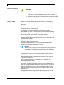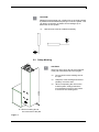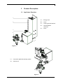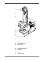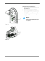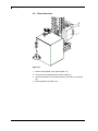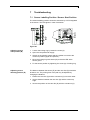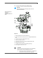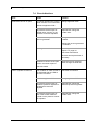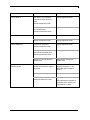
1
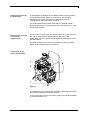
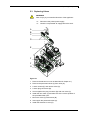
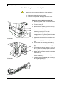
APX 7000 Service Instructions Copyright by Carl Valentin GmbH / 799752508.14 Information on the scope of delivery, appearance, performance, dimensions and weight reflect our knowledge at the time of printing. We reserve the rights to make modifications. All rights, including those regarding the translation, are reserved. No part of this document may be reproduced in any form (print, photocopy or any other method) or edited, copied or distributed electronically without written permission from Carl Valentin GmbH. Due to the constant further development of our devices discrepancies between manual and device can occur. Please check www.carl-valentin.de for the latest update. Trademarks All named brands or trademarks are registered brands or registered trademarks of their respective owners and may not be separately labelled. It must not be concluded from the missing labelling that it is not a registered brand or a registered trademark. Carl Valentin print modules comply with the following safety guidelines: CE EG Low-Voltage Directive (2006/95/EC) EG Electromagnetic Compatibility Directive (2004/108/EG) EG Machinery Directive (2006/42/EG) Carl Valentin GmbH Postfach 3744 78026 Villingen-Schwenningen Neckarstraße 78 – 86 u. 94 78056 Villingen-Schwenningen Phone Fax +49 (0)7720 9712-0 +49 (0)7720 9712-9901 E-Mail Internet [email protected] www.carl-valentin.de APX 7000 Table of Contents Table of Contents Table of Contents ............................................................................. 3 08.14 1 1.1 1.2 1.3 2 2.1 2.2 3 3.1 3.2 3.3 4 4.1 4.2 5 5.1 5.2 5.3 5.4 5.5 5.6 6 6.1 6.2 7 7.1 7.2 7.3 7.4 8 Notes on this Document ....................................................... 5 User Notes............................................................................... 5 Instructions .............................................................................. 5 Cross References .................................................................... 6 Safety Instructions ................................................................ 7 General Safety Instructions ..................................................... 7 Safety Marking.................. Fehler! Textmarke nicht definiert. Product Description ............................................................ 11 Applicator Overview............................................................... 11 Sensor ................................................................................... 14 Pneumatic.............................................................................. 15 Maintenance and Cleaning ................................................. 18 Tools ...................................................................................... 18 Cleaning ................................................................................ 18 Replacing Components ...................................................... 19 Removing the Covers ............................................................ 19 Sticking Slide Foil onto the Pad............................................. 20 Replacing Valves ................................................................... 21 Replacing PCB ...................................................................... 22 Replacing Cylinder ................................................................ 23 Replacing Sensors at the Cylinder ........................................ 24 Refitting Options ................................................................. 27 'Quick Apply' .......................................................................... 27 Shock Absorber ..................................................................... 28 Troubleshooting .................................................................. 29 Sensor Labelling Position / Sensor Start Position ................. 29 Supporting Air Throttle Pressure Measuring ......................... 30 Vacuum Throttle Pressure Measuring ................................... 31 Error Indications .................................................................... 32 Wiring Plan ........................................................................... 35 9 Pneumatic Plan .................................................................... 36 10 Connector Pin Assignment of PCB ................................... 37 11 Environmentally-Friendly Disposal ................................... 38 12 Index ..................................................................................... 39 Service Instructions 3 APX 7000 Notes on this Document 1 Notes on this Document 1.1 User Notes This service manual is intended for qualified service and maintenance staff. This manual contains information about the applicator APX 7000. Information about operation of the print module can be taken from our operating manual. If a problem arises that cannot be solved with help of this service instructions, then please contact your responsible dealer. 1.2 Instructions Basic information and warning references with the corresponding signal words for the danger level are as follows specified in this manual: DANGER identifies an extraordinarily great and immediate danger which could lead to serious injury or even death. WARNING identifies a possible danger would could lead to serious bodily injury or even death if sufficient precautions are not taken. CAUTION indicates a potentially dangerous situation which could lead to moderate or light bodily injury or damage to property. NOTICE gives you tips. They make a working sequence easier or draw attention to important working processes. Gives you tips on protecting the environment. 08.14 Handling instruction Optional accessories, special fittings Date Information in the display Service Instructions 5 Notes on this Document APX 7000 1.3 Cross References Item numbers References to specific items in a figure are marked with item numbers. They are identified with parentheses in the text, e.g. (9). If no figure number is provided, item numbers in the text always refer to the graphic directly above the text. If a reference is made to another graphic, the figure number is specified, e.g. (2, in figure 5). Cross references to chapters and sections For a cross reference to chapters and sections, the chapter number and page number are specified, e.g. a reference to this section: see chapter 1.3.2, on page 35). References to other documents References to other documents have the following form: See 'operating manual'. 6 Service Instructions 08.14 APX 7000 Safety Instructions 2 Safety Instructions 2.1 General Safety Instructions Workplace and method of working Clothing Keep the area around the applicator clean during and after maintenance. Work in a safety-conscious manner. Store dismantled device parts in a safe place while maintenance is being performed. CAUTION! The drawing in of items of clothing by moving parts can lead to injuries. If possible, do not wear clothing which could be caught by moving device parts. Button or roll up shirt or jacket sleeves. Tie or pin up long hair. Tuck the ends of scarves, ties and shawls into your clothing or secure them with non-conductive clips. DANGER! Risk of death from increased flow of current via metals parts which come into contact with the device. Protective clothing 08.14 Do not wear clothing with metal parts. Do not wear jewellery. Do not wear glasses with a metal frame. If a possible danger to your eyes is present, wear protective goggles, especially in the following cases: when knocking in or knocking out pins and similar parts with a hammer when using an electric drill when using spring hooks when loosening or inserting springs, snap rings and gripping rings when soldering when using solvents, cleaning agents or other chemicals Service Instructions 7 Safety Instructions Protective equipment APX 7000 WARNING! Risk of injury in case of missing or faulty protective equipment. General safety instructions After performing maintenance work, attach all safety equipment (covers, safety precautions, ground cables etc.). Replace faulty parts and those which have become unusable. Before mounting the delivered components disconnect the printing system from the power supply and close the shutoff valve at the applicator. Couple the applicator to devices using extra low voltage only. Before making or undoing connections, switch off all devices involved (computer, printer, accessories etc.). In operation, moving parts are easily accessible. This applies especially for the zone, where the pad is moved between the starting and the labelling position. During operation do not reach into that zone and keep long hair, loose clothes, and jewellery distant. Before any manipulations in those areas, close the shutoff valve. Operate the applicator in a dry environment only and do not get it wet (sprayed water, mist etc.). Do not operate the applicator in explosive atmosphere and not in proximity of high voltage power lines. Operate the applicator only in an environment protected against abrasive dust, swarf and other similar impurity. NOTICE! With the open printing unit (due to construction) the requirements of EN60950-1 regarding fire protection casing are not fulfilled. These must be ensured by the installation into the end device. Carry out only the actions described in these operating instructions. Any work beyond this may only be performed by epecially trained personnel or service techniciens. Unauthorized interference with electronic modules or their software can cause malfunctions. Other unauthorized work or modifications to the applicator can endanger operational safety. There are warning stickers on the applicator that draw your attention to dangers. Therefore the warning stickers are not to be removed as then you and others cannot be aware of dangers and may be injured. When incorporating the unit into the overall system, make sure that safety precautions are taken so that no-one is able to reach into the working area. The applicator must be integrated with the Emergency Stop circuit when it is incorporated into the overall machine. 8 Service Instructions 08.14 APX 7000 Safety Instructions CAUTION! Damages of the plunger rod, cylinder tube or the seals caused by lateral forces that affect the plunger rod of the cylinder. This can lead to a reduction of lifetime and to leakages up to destruction of the cylinder. Lateral forces must be avoided necessarily. F F 2.2 Safety Marking CAUTION! There is a risk of injury due to the movement of the pad downwards and back up again. Do not reach into the working area of the pad. Keep hair, loose clothing and items of jewellery out of this area. When incorporating the unit into the overall system, safety precautions must be taken so that no-one is able to reach into the working area. A A = Risk of crushing due to A = the movement of the pad Figure 1 08.14 Service Instructions 9 APX 7000 Product Description 3 Product Description 3.1 Applicator Overview A B A= Energy track B= Cover C= Locking pin with interlock D= Compressed air connector E= Cover C D E Figure 2 F F= Connection applicator-printing system G= Service unit G Figure 3 08.14 Service Instructions 11 Product Description APX 7000 H I J K L M N O P Q R Figure 4 12 H= Stopper I= Throttling back valve 'cylinder' (top) J= Sensor top end position K= Stroke cylinder L= Shock absober (option) M= Throttling back valve 'cylinder' (bottom) N= Sensor bottom end position O= Pad retainer P= Pad Q= Plastic ring R= Supporting air tube Service Instructions 08.14 APX 7000 Product Description S T U V W X Y Z Figure 5 08.14 S= Valve 'Quick Apply' (option) T= Throttle 'Quick Apply' (option) U= Throttling valve blowing air V= Throttling valve vacuum W= Valve stroke cylinder X= Valve blowing air Y= Valve vacuum/supporting air Z= Throttling valve supporting air Service Instructions 13 Product Description APX 7000 3.2 Sensor Sensor labelling position The impact of the pad on the product and the reaching of the blow-off position are detected by means of an inductive proximity switch and a spring-mounted cam disc. The distance between the cam disc and the inductive proximity switch is used. Sensor start position The start position is the upper end position of cylinder and the position of the pad which takeover the label from printer. This position will detected via a Reed-sensor in interaction with a magnet mounted inside cylinder. Sensor vacuum The correct transfer of a label will be checked by the vacuum sensor. It also checks that there is no longer a label on the pad in case the return movement. This sensor is integrated to the APX connection PCB. Sensor pressure The pressure sensor controls the pressure air. This sensor is integrated to the APX connection PCB. 14 Service Instructions 08.14 APX 7000 Product Description 3.3 Pneumatic Cylinder A cylinder with stroke of 100 … 500 mm is used for the transport of labels between the peel-off edge of the printer and the labelling position. The movement of cylinder is controlled by a control valve on the valve block. The speed of movement can be changed by two throttle valves mounted at cylinder. Pad The label will be transported by a pad. The pad must be appropriate to the size of label. During the label transport a vacuum is applied on the pad. In operating mode 'blow on' in the lower final position the label is applied by a high pressure. Vacuum generator The vacuum at the pad is produced by a vacuum generator. The vacuum generator is controlled by control valve on the valve block. The low pressure can be adjusted by a throttle valve. Blow tube Air is blown from below (supporting air) trough a blow tube onto the label in order to support the transfer of the label from the printer to the pad. The blow tube is adjustable concerning the blowing direction. The supporting air is connected by the magnet valve (support air). The power of the supporting air can be adjusted by a throttle valve at the valve block. Pneumatic maintenance unit The pneumatic maintenance unit is offered as an option for the applicator. The important components of the pneumatic maintenance unit are a pressure reducer with manometer, a water separator with micro filter and a main connector for compressed air. Valve block The distribution of the compressed air to the various pneumatic units is made in the valve block. On the valve block is mounted the control valve for support air and vacuum with their throttle valves and the control valves for the lift cylinder and blow air. 08.14 Service Instructions 15 Product Description Control valves APX 7000 NOTICE! For adjustments of certain applicator functions it is possible to release the control valves in the pneumatic system. The control valves are accessible only with dismounted protective covers for electronics and cylinder. E N E N F G N A B C D H I J K L M O Figure 6 1. Loosen screws (N) and remove cover for electronics (O). 2. The compressed air control valves can be controlled manually with integrated switch (A-C, I, J, M). 3-way valve (K) to control the lift cylinder If the printer is switched on the valve will controlled by electronics and the tamp will hold in the upper end position (home position). If the valve switched the tamp will move in the lower end position (labelling position). In normal labelling operation the movement back in the upper end position will start by a signal from labelling sensor. NOTICE! The switching by hand of this valve has only a result in case of a switched off printer. Switching the valve by hand over switch (I) the tamp will move down up to the lowest possible position because no control is made by the sensor. Switching the valve by hand over switch (A) the tamp will move up. 16 Service Instructions 08.14 APX 7000 Double 2-way valve (L) for blowing air Product Description In the operation mode 'Blow on' the label will blow up to the product. In the operating modes 'Stamp on' and 'Roll on' the blow air is switched on for a short time after each application to avoid contaminations within the vacuum channels. For all described functions both valves will be controlled parallel. By pressing the keys (J) or (B) the blow air is only switched on by one of both internal valves. Double 2-way valve (D) for vacuum / supporting air The two internal valves serve the vacuum nozzle for connecting an in this way for creating the negative pressure at the tamp and independent of this for connecting the support air at the blow tube for the label transfer. By pressing switch (C) the vacuum is switched on and by pressing switch (M) the supporting air is switched on. 2-way valve (A) for option 'Quick Apply' A B C Figure 7 The absorption may be adjusted by rotating the adjusting screw (B) at the exhaust throttle of the solenoid valve (A). In the "quick apply" menu of the printing system, set the desired delay for valve activation in ms. 08.14 Service Instructions 17 Maintenance and Cleaning APX 7000 4 Maintenance and Cleaning 4.1 Tools For Assemblies Tools Size Cylinder plunger Spanner wrench 25,0 mm Throttling valves cylinder Throttling valve vacuum, blowing air L-connector, cam disk (valve block in service unit) Lift cylinder Valve block, energy track 28,0 mm 12,0 mm 14,0 mm 22,0 mm Hexagon wrench 22,0 mm PCB 22,5 mm Adjustment guiding block 24,0 mm Throttle valves Valves on the valve block Sensors (labelling sensor + sensor start position) Works at PCB Pressure measurement Screwdriver for slotted screws Crosstip screwdriver 22,5 mm PH 0 PH 2 Wrist grounding Manometer to approx. 5 bar Cloth soft brush, multi purpose cleaner (without solvent) 4.2 Cleaning CAUTION! Abrasive cleaning agents can damage the applicator! Do not use abrasives or solvents to clean the outer surface of the label printer. Clean the outside surfaces with multipurpose cleaner. Remove dust particles and label splits with a soft brush or a vacuum cleaner. The ideal takeover and handling of the label can be achieved by cleaning the surface of slide foil (A) at regular intervals. 18 Service Instructions 08.14 APX 7000 Replacing Components 5 Replacing Components WARNING! Risk of injury by uncontrolled functions of the applicator. Disconnect the printer power supply. Close the compressed air supply before the work. 5.1 Removing the Covers NOTICE! Dismantle the cover to arrive the components installed on the carrier plate. Remove cylinder cover 1. Loosen screws (B). 2. Remove cover (A). Remove electronics cover 1. Loosen screws (D). 2. Remove cover (C). A E D B D B D C Figure 8 NOTICE! Before starting the normal operation mount the covers again. 08.14 Service Instructions 19 Replacing Components APX 7000 5.2 Sticking Slide Foil onto the Pad A B C Figure 9 1. Dismount the pad unit (B). 2. Remove the slide foil (A) completely. 3. Clear the surface from remains of glue. 4. Remove covering foil from the slide foil (A). 5. Put the slide foil (A) with its adhesive side onto the pad (B). Press the slide foil firmly on the pad. 6. Cut off overlapping parts of the slide foil (A) according to the broken line of the pad (B). 7. Punch the slide foil (A) on the pad (B) using the punch pin (C) appropriate to the whole pattern on the wearing slide foil. 8. Punch the hole completely by turning the pin. 9. Mount the pad unit (B). 20 Service Instructions 08.14 APX 7000 Replacing Components 5.3 Replacing Valves WARNING! Risk of injury by uncontrolled functions of the applicator. Disconnect the printer power supply. Close the compressed air supply before the work. A B C D E F F G Figure 10 1. Remove the electronics cover as described in chapter 5.1). 2. Remove the pneumatic tubes (A) from valve (G). 3. Loosen screws (F) and remove valve (G). 4. Loosen plug connectors (B). 5. Screw together the plug connector (B) with new valve (C). 6. Install the new valve (C) and take care of the correct position of the provided rubber joint. 7. Mount the valve (C) with screws (B). 8. Insert again the pneumatic tubes (A). 9. Install the electronics cover (E). 08.14 Service Instructions 21 Replacing Components APX 7000 5.4 Replacing PCB WARNING! Risk of injury by uncontrolled functions of the applicator. Disconnect the printer power supply. Close the compressed air supply before the work. A B C D E E B F Figure 11 1. Remove the electronics cover (A) as described in chapter 5.1). 2. Remove connector (E). 3. Remove pneumatic tubes from pressure sensors and vacuum sensors (F). 4. Remove cable (D) from PCB (C). 5. Loosen screws (B). 6. Remove PCB (C). 7. Install the new PCB (C) and fix it with screws (B). 8. Connect cable (D) with PCB (C). 9. Insert the pneumatic tubes (F). 10. Connect the plug connector (E) with PCB (C). Take care of the cable marking. 11. Install again the electronics cover (A). NOTICE! Do not forget the connecting position for the re-installation! 22 Service Instructions 08.14 APX 7000 Replacing Components 5.5 Replacing Cylinder WARNING! Risk of injury by uncontrolled functions of the applicator. Disconnect the printer power supply. Close the compressed air supply before the work. A 1. Remove the cylinder cover (see chapter 5.1). 2. Disassemble the sensor upper end position (A) with fastening clamp. Remove tubes from cylinder (C). B C 3. Unscrew throttling valves (B, D) from cylinder. 4. Loosen the counternut (H) from the cylinder piston rod (E) using a size 10 spanner wrench while holding the coupling (I) with a size 8 spanner wrench. 5. Remove the cylinder piston rod (E) from the coupling (I) by rotating it. 6. Remove the fastening nut (G) while noting the fastening position of the cylinder. D 7. Remove cylinder (C) from holder (F). 8. Insert the new cylinder (C) into the support (F) and attach it with the fastening nut (G). Ensure a correct cylinder position. E F 9. Insert the cylinder piston rod (E) into the coupling (I) by rotating it. G 10. Attach the cylinder piston rod (E) with the counternut (H) while holding the coupling (I). 11. Mount the throttling valves (B, D). H I 12. Mount again the sensor upper end position (A) and tubes. 13. Install again the cylinder cover. NOTICE! Figure 12 After replacing a cylinder the sensor positions are to be adjusted (see chapter 5.6). 08.14 Service Instructions 23 Replacing Components APX 7000 5.6 Replacing Sensors at the Cylinder WARNING! Risk of injury by uncontrolled functions of the applicator. Disconnect the printer power supply. Close the compressed air supply before the work. Replacing sensor labelling position (A) 1. Remove cylinder cover and electronics cover (see chapter 5.1). 2. Loosen screws (C). 3. Remove sensor holder (D) with sensor (A). A B C D E Figure 13 4. Remove screws (B). 5. Remove the screws (G) in order to loosen the energy track (F) on one side. 6. Detach the T-shaped parts (I) hooked together from the U-shaped parts (H) of the energy track (see Figure 16). 7. Pull out the sensor (A) from the energy track (F). 8. Remove the plug (L) of sensor (A) from PCB (K). 9. Connect the new sensor (A) with PCB (K). F G 10. Insert the new sensor (A) in the energy track (F). 11. Close again the energy track (F). In order to do so, press the T-shaped parts (I) into the U-shaped parts (H). 12. Mount again the energy track (F) and tighten the screws (G). 13. Mount the sensor (A) with screws (B) at the sensor holder (F). 14. Install the sensor holder (D) with screws (C) at the guiding plate (E). Figure 14 H I Figure 15 24 Service Instructions 08.14 APX 7000 Replacing Components Replacing sensor start position (J) 1. Remove cylinder cover and electronics cover (see chapter 5.1). 2. Remove sensor plug (J) from PCB (K). 3. After loosening the small thread pin, remove the start position sensor (J) from the support and replace it. 4. Connect the plug of the new sensor (J) with PCB (K). NOTICE! J After replacing a sensor its new position is to be adjusted (see chapter 7.1, page 29). Figure 16 K L Figure 17 08.14 Service Instructions 25 APX 7000 Refitting Options 6 Refitting Options WARNING! Risk of injury by uncontrolled functions of the applicator. Disconnect the printer power supply. Close the compressed air supply before the work. 6.1 'Quick Apply' F E A D B C Figure 18 1. Remove electronics cover (see chapter 5.1). 2. Mount the option 'Quick Apply' (D) with screws (E) at the retaining ledge (F). 3. Remove blind bolt (C). 4. Connect the plug of the valve (A) with the ST9 slot (B) on the PCB. 5. The piping system is established according to the pneumatic diagram (see chapter 9, page 36). 6. Mount again the electronics cover. 08.14 Service Instructions 27 Refitting Options APX 7000 6.2 Shock Absorber G H I Figure 19 1. Remove the cylinder cover (see chapter 5.1). 2. Screw the shock absorber (G) into the cabinet (I). 3. Secure the position of the shock absorber (G) with the counternut (H). 4. Mount again the cylinder cover. 28 Service Instructions 08.14 APX 7000 Troubleshooting 7 Troubleshooting 7.1 Sensor Labelling Position / Sensor Start Position The sensor labelling position shows the activation by a LED integrated in the sensor. This LED glows in case of activation. A B C D E Figure 20 Adjusting sensor start position (B) 1. Loosen the locking ring by loosen the screw (A). 2. Open the compressed air supply. 3. Switch on the printing system and the cylinder is moved to the maximum position (upper end position). 4. Move the locking ring with sensor (B) so that the LED at the sensor glows. 5. Fix the sensor position by tightening the screw (A) of locking ring. Adjusting sensor labelling position (E) The distance between the sensor (E) and the cam disc (D) should be at least 2 mm. The printing time of the pad may be adjusted by changing the distance. 1. Detach the cam disc (D) and the counternut (C) from each other. 2. Set the distance between the cam disc (D) and the sensor top edge. 3. Secure the position of the cam disc (D) with the counternut (C). 08.14 Service Instructions 29 Troubleshooting APX 7000 7.2 Supporting Air Throttle Pressure Measuring NOTICE! Use a manometer with a measuring scale to 5 bar for measuring the pressure. Measuring point 1: Supporting air (reference value 1,5 bar) A B C D E Figure 21 1. Remove the electronics cover (see chapter 5.1). 2. Unscrew the throttling valve (C) from supportig air holder and screw it at the measuring device (E). 3. Screw a threaded union (B) onto the throttling valve position. 4. Connect with tubes (A-C and B-D). 5. Switch on pressure 'supporting air'. 6. If needed, set the pressure at the throttling valve (C). 7. After measuring and setting, mount again the throttling valve (C) at the supporting air holder. 8. Mount again the electronics cover. CAUTION! Malfunction at label takeover from dispenser edge to pad. Not enough vacuum / air de support. 30 After the pressure measuring reconnect all connectors and check the interference fit of the tubes. Service Instructions 08.14 APX 7000 Troubleshooting 7.3 Vacuum Throttle Pressure Measuring NOTICE! Use a manometer with a measuring scale to 5 bar for measuring the pressure. Measuring point 2: Vacuum (reference value -0.4 bar) E D C A B Figure 22 1. Remove electronics cover (see chapter 5.1). 2. Remove the vacuum tube (A) from the Y-shaped threaded union (B). 3. Connect the vacuum measuring device (D). 4. Switch on pressure 'vacuum'. 5. Sealing the point (E) of the vacuum measuring device (D). 6. Measure the vacuum value. 7. If needed, set the pressure at the thottling valve (C). 8. Mount again the electronics cover. CAUTION! Malfunction during the label transfer from the dispensing edge to the pad. Vacuum/supporting air too low. 08.14 Following the pressure measurement, re-establish the connections and check the tubes for tightness. Service Instructions 31 Troubleshooting APX 7000 7.4 Error Indications Error Cause Solution Insufficient vacuum on pad In cyclical operation the control valve 'vacuum' is not controlled. Change applicator PCB. Defective applicator PCB. No pressure at the output of throttle valve 'vacuum' or the pressure cannot be adjusted. Adjust and/or change the throttle valve. No vacuum at output of vacuum generator. Change the sound absorber if it is soiled. Change the vacuum generator if it is defect. Leaking vacuum chain. Measuring as described in chapter 7.2, page 30. Check the transmission elements and replace them if necessary. Insufficient vacuum at the pad. Suction channels at pad or slide foil clotted. Fault in cylinder movement 32 Clean the suction channels and/or change the slide foil. The condition of valve control is not indicated with the LED at the valve connector. Check the connections. Defective applicator PCB. Change applicator PCB. No pressure at the output of miniature pressure regulator or the pressure cannot be adjusted. Adjust and/or change the miniature pressure regulator. No pressure at the output of one of the throttle valves at cylinder or the pressure cannot be adjusted. Adjust and/or change the throttle valve. Service Instructions 08.14 APX 7000 Troubleshooting Error Cause Solution Loss of blow air The valve is not activated. Change applicator PCB. The LED at valve does not glow. Defective applicator PCB. Insufficient pressure at pad with an activated valve. Replace pneumatic tubes. Defective pneumatic tubes. Loss of applicator funciton Loss of support air Compressed air failure. Check connections. Defective applicator PCB. Change applicator PCB. Valve is not controlled. Change applicator PCB. Defective applicator PCB. Insufficient pressure at blow tube with an activated valve. Change pneumatic tubes. Defective pneumatic tubes. Permanent error at label transfer via pad Defective or wrong adjusted throttle valve. Adjust and/or change the throttle valve. Faulty pad position in transfer position to the peel off edge of the printer. Correct position (backward edge of pad approx. 1 mm above the peel off edge of printer). Insufficient or missing vacuum. Adjust vacuum at throttle valve. Support air does not blow exactly the label to the pad. Adjust the blow tube. Adjust pressure of support air via throttle valve 'support air'. Adjust switch on delay. 08.14 Service Instructions 33 APX 7000 Wiring Plan 8 Wiring Plan Figure 23 08.14 Service Instructions 35 14 1V4 K1 14 Pos.14 1V5 Service Instructions P1 5 4 2 1 2 1 2 1 3 2 Pos.1 Pos.2 3 BU RL BN 1 2 I 12 BU R L B1 BN 3 K2 Pos.4 1 Pos.3 P B4 Pos.8 B3 1 BN BK R L 4 BU PNP 3 2V1 K2 14 3V1 1 4 5 12 1 2 Pos.9 2 3 Pos. 11 = Service unit Pos. 12 = Distributor block Pos. 13 = Pressure sensor Pos. 14 = Valve cluster Pos. 15 = Throttling back valve, outcoming air Pos. 16 = Throttling back valve, outgoing air Pos. 17 = Plunger cylinder Buffer Used for preparing printing zones. Separators are inserted in opening 3 and 5. 3V2 K2 14 1 4 1 2 5 Pos.10 4V4 Pos.11 12 4A1 4V3 2 1 2 3 supporting air K1 Pos.13 Pos. 18 = Proximity switch Pos. 19 = Throttling back valve, outgoing air Pos. 10 = Throttling back valve, incoming air Pos. 11 = Vacuum suction nozzle Pos. 12 = Vacuum sensor Pos. 13 = Throttling back valve, icoming air Pos. 14 = Brake valve (option) K1 4V1 BU R L B2 BN 3 3 1 4V2 I Pos.12 P 9 1V1 K1 12 1 Pos.6 1 1V2 2 Pos.5 2 1V3 1A1 Pos.7 3A1/4A1 2 36 1 Plunger cylinder double-acting Pad vakuum/blowing Pneumatic Plan APX 7000 Pneumatic Plan Figure 24 08.14 APX 7000 Connector Pin Assignment of PCB 10 Connector Pin Assignment of PCB Figure 25 08.14 Service Instructions 37 APX 7000 Environmentally-Friendly Disposal 11 Environmentally-Friendly Disposal Manufacturers of B2B equipments are obliged to take-back and dispose old equipment which was manufactured after 13 August 2005. In principle, these old equipments may not be delivered to communal collecting points. They may only be organised used and disposed by the manufacturer. Valentin products accordingly labelled can therefore in future be returned to Carl Valentin GmbH. Thereupon old equipment is professionally disposed. Thereby Carl Valentin GmbH observes all obligations in the context of old equipment disposal in time and makes therewith the smooth selling of products furthermore possible. Please understand that we can only take-back equipment that is send free of carriage charges. Further information on the WEEE directive is available on our website www.carl-valentin.de. 08.14 Service Instructions 38 APX 7000 Index 12 Index C Cleaning ............................................................................................. 18 Connector pin assignment, PCB ........................................................ 37 Cylinder cover, remove ...................................................................... 19 Cylinder, replacing.............................................................................. 23 D Document notes ................................................................................... 5 E Electronics cover, remove .................................................................. 19 Environmentally-friendly disposal ....................................................... 38 I Instructions ........................................................................................... 5 O Overview, applicator ............................................................... 11, 12, 13 P Pad, sticking slide foil ......................................................................... 20 PCB, replacing ................................................................................... 22 Pneumatic Blow tube ........................................................................................ 15 Control valves ........................................................................... 16, 17 Cylinder ........................................................................................... 15 Maintenance unit ............................................................................ 15 Pad.................................................................................................. 15 Vacuum generator .......................................................................... 15 Valve block ..................................................................................... 15 Pneumatic plan ................................................................................... 36 Pressure measuring Supporting air throttle ..................................................................... 30 Vacuum throttle............................................................................... 31 Q Quick Apply, refitting .......................................................................... 27 R Refit options Quick Apply ..................................................................................... 27 Shock absorber............................................................................... 28 S Safety instructions ................................................................................ 8 Clothing ............................................................................................. 7 Protective clothing ............................................................................ 7 Protective equipment ........................................................................ 8 Workplace ......................................................................................... 7 08.14 Service Instructions 39 Index APX 7000 Safety marking ..................................................................................... 9 Sensor Labelling position ............................................................................ 14 Pressure ......................................................................................... 14 Replacing .................................................................................. 24, 25 Start position ................................................................................... 14 Troubleshooting .............................................................................. 29 Vacuum ........................................................................................... 14 Shock absorber, refitting .................................................................... 28 T Tools ................................................................................................... 18 Troubleshooting Error indication .......................................................................... 32, 33 Pressure measuring.................................................................. 30, 31 Sensor start position ....................................................................... 29 U User notes ............................................................................................ 5 V Valves, replacing ................................................................................ 21 W Wiring plan ......................................................................................... 35 40 Service Instructions 08.14 Carl Valentin GmbH Neckarstraße 78 – 86 u. 94 . 78056 Villingen-Schwenningen Phone +49 (0)7720 9712-0 . Fax +49 (0)7720 9712-9901 [email protected] . www.carl-valentin.de