1
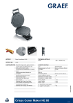
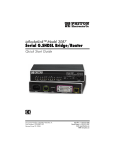
Quick Reference Guide
Brakes
••
••
••
••
•
101
Suspension
111
General Information
1
Fuel System
2
3
Cooling System
Engine Top End
4
Engine Right Side
5
Engine Removal/Installation
6
Engine Bottom End/Transmission
7
WheelslTires
8
9
Final Drive
This quick reference guide will assist you in
locating a desired topic or procedure.
• Bend the pages back to match the black tab
of the desired chapter number with the black
tab on the edge at each table of contents
page.
• Refer to the sectional table of contents for
the exact pages to locate the specific topic
required.
12 •
Steering
1
Electrical System
1131
Appendix
1141
Kawasaki
KX125
KX250
Motorcycle
Service Manual
LIST OF AB BREVIATIONS
A
ABOC
AC
ATDC
BBOC
BOC
BTDC
"C
DC
F
"F
ft
9
h
L
ampere(s)
Ib
aher bottom dead center
m
alternating current
min
N
after top dead center
before bottom dead center
bottom dead center
before top dead center
Pa
PS
psi
pounds(s)
meter(s)
minute(s)
newton(s)
pascal(s)
horsepower
pound(s) per SQuare inch
revolution
degree(s) Celsius
,
direct current
farad(s)
degree(s) Fahrenheit
TOC
TIR
top dead center
total indicator reading
V
volt(s)
W
watt(s)
foot, feet
gram(s)
hour(s)
liter(s)
'pm
n
revolution(s) per minute
ohm(s)
Read OWNER'S MANUAL before operating.
Foreword
This manual is designed primarily for use by
trained mechanics in a properly equipped shop .
However, it contains enough detail and basic
information to make it useful to the owner who
desires to perform his own basic maintenance and
repair work. A basic knowledge of mechanics, the
proper use of tools, and workshop procedures must
be understood in order to carry out maintenance and
repair satisfactorily. Whenever the owner has
insufficient experience or doubts his ability to do the
work, all adjustments, maintenance. and repair
should be carried out only by Qualified mechanics .
In order to perform the work efficiently and to
avoid costly mistakes, read the text, thoroughly
familiarize yourself with the procedures before
starting work. and then do the work carefully in a
clean area , Whenever special tools or equipment are
specified. do not use makeshih tools or equipment.
Precision measurements can only be made if the
proper instruments are used. and the use of substi tute tools may adversely affect safe operation .
We recommend that all repairs and scheduled
maintenance be performed in accordance with this
service manual.
To get the longest life out of your Motorcycle :
• Follow the Periodic Maintenance Chart in the
Service Manual.
• Be alert for problems and non-scheduled maintenance .
• Use proper tools and genuine Kawasaki Motorcycle parts. Special tools. gauges. and testers that
are necessary when seNicing Kawasaki Motorcycles are introduced by the Special Tool Manual.
Genuine pans provided as spare pans are listed in
the parts Catalog .
• Follow the procedures in this manual carefully.
Don't take shortcuts.
• Remember to keep complete records of maintenance and repair with dates and any new parts
installed .
How to Use this Manual
In preparing this manual. we divided the product
into its major systems. These systems became the
manual's chapters. All information for a particular
system from adjustment through disassembly and
inspection is located in a single chapter.
The Ouick Reference Guide shows you all of the
product's system and assists in locating their
chapters. Each chapter in turn has its own comprehensive Table of Contents.
The Periodic Maintenance Chart is located in the
General Information chapter. The chart gives a time
schedule for required maintenance operations.
If you want spark plug information. for example,
go to the Periodic Maintenance Chart first. The chart
tells you how frequently to clean and gap the plug.
Next, use the Ouick Reference Guide to locate the
Electrical System chapter. Then, use the Table of
Contents on the first page of the chapter to find the
Spark Plug section .
Whenever you see these WARNING and
CAUTION symbols, heed their instructions! Always
follow safe operating and maintenance practices.
AWARNING
This warning symbol identifies special instruction , or
procedures which. jf not correctly followed. could
r&luh in Pfjrll(tnal injury. or loss of life .
CAUTION
This caution symbol identifies special instructions o r
procedures which, If not strictly observed. could r8ltllt
in dsmage to or destruction of equipment.
This manual contains fOur more symbols (in
addition to WARNING and CAUTION) which will
help you distinguish different types of information.
NOTE
o
This note symbol indicates points of particular interest
mor" efficient and convenient operation.
fOf
• Indicates a procedural step or work to be done.
01 ndicates a procsdural sub-step or how to do the work
of the procedural step it follows. It also precedes the
text of 8 WARNING, CAUTION, or NOTE.
* Indicates a conditional step or what action to take based
on the results of the test or inspection in the procedural
step or sub-step i1 follows.
In most chapters an exploded view illustration of
the system components foHows the Table of
Contents. In these illustrations you will find the
instructions indicating which parts require specified
tightening torque, oil. grease or a locking agent
during assembly.
GENERAL INFORMATION 1 -1
General Information
Table of Contents
Before Servicing ................ ......................................... ............ .......................
...1-2
Model Identification ...........
.................................. ................................................1-4
General Specifications ................................................. .............................................. .1-6
Periodic Maintenance Chart .....................................................................................1-10
Torque and locking Agent ......................................... ...... ....... ............................. ...., -, 1
Special Tools. Sealant ...............................................................................................1 -14
Cable. Harness. Hose Routing ..................................................................................1 -18
1 - 2 GENERAL INFORMATION
Before Servicing
Before starting to service a motorcycle, careful reading of the applicable section is recommended to eliminate
unnecessary work. Photographs, diagrams. notes, cautions, warnings, and detailed descriptions have been
included wherever necessary. Nevertheless, even a detailed account has limitations, a certain amount of basic
knowledge is also required for successful work.
Especially note the following:
(1) Di~
Before removal and disassembly. clean the motorcycle . Any dirt entering the eng ine or other parts will
work as an abrasive and shorten the life of the motorcycle. For the same reason, before installing a new
part, clean off any dust or metal filings.
(2) Tightening Sequence
Generally. when installing a part with several bolts, nuts, or screws, start them all in their holes and
tighten them to a snug fit. Then tighten them evenly in a cross pattern. This is to avoid distortion of the
part and/ or causing gas or oil leakage . Conversely when loosening the bolts, nuts, or screws, first loosen
atl of them by about a quarter of turn and then remove them. Where there is a tightening sequence
indication in this SelVice Manual. the botts, nuts, or screws must be tightened in the order and method
indicated.
(3) Torque
When torque values are given in this SelVice Manual. use them . Either too little or too much torque may
lead to serious damage. Use a good quality, reliable torque wrench.
(4) Force
Common sense should dictate how much force is necessary in assembly and disassembly. If a part seems
especially difficult to remove or install, stop and examine what may be causing the problem . Whenever
tapping is necessary, tap lightly using a wooden or plastic -faced mallet. Use an impact driver for screws
(particularly for the removal of screws held by a locking agent) in order to avoid damaging the screw heads.
(5) Edges
Watch for sharp edges, especially during major engine disassembly and assembly. Protect your hands
with gloves or a piece of thick cloth when lifting the engine or turning it over.
(6) High - Flash Point Solvent
A high-ftash point solvent is recommended to reduce fire danger. A commercial solvent commonty
available in North America is Stoddard solvent (generic name) . Always follow manufacturer and container
directions regarding the use of any solvent.
(7) Gasket, O- Ring
Do not reuse a gasket or O-ring once it has been in selVice. The mating surfaces around the gasket
should be free of foreign maner and perfectly smooth to avoid oil or compression leaks.
(8) Liquid Gasket. Non - Permanent Locking Agent
Follow manufacturer's directions for cleaning and preparing surfaces where these compounds will be
used. Apply sparingly. Excessive amounts may block engine oil passages and cause serious damage. An
example of a non -permanent locking agent commonly available in North America is Loctite Lock' n Seal
(Blue) .
(9) Pross
A part installed using a press or driver, such as a wheel bearing, should first be coated with oil on its outer
or inner circumference so that it will go into place smoothly.
(10) Ball Bearing and Needle Bearing
Do not remove any ball or needle bearings that are pressed in unless it is necessary. If they are removed,
replace them with new ones.
When installing a bearing, press it in with the marked side facing out using a suitable driver until it is
bottomed. Bearings should be pressed into place by pushing evenly the bearing race which is affected by
friction.
(11) Oil Seal and Grease Seal
Replace any oil or grease seals that were removed with new ones, as removal generally damages seals.
When pressing in a seal which has manufacturer's marks, press it in with the marks facing out. Seals
shou ld be pressed into place using a suitable driver, which contacts evenly with the side of seal, until the
face of the seal is even with the end of the hole.
•
GENERAL INFORMATION 1 - 3
(12) Seal Guide
A seal guide is required for certain oil or grease seals during installation to avoid damage to the seal lips.
Before a shaft passes through a seal, apply a linle high temperature grease on the lips to reduce rubber to
metal friction .
(13) Circlip, Retaining Ring
Replace any circtips and retaining rings that were removed with new ones, as removal weakens and
deforms them . When installing circlips and retaining rings, take care to compress or expand them only
enough to install them and no more.
(14) Coner Pin
Replace any coner pins that were removed with new ones, as removal deforms and breaks them.
(15) lubrication
Engine wear is generally at its maximum while the engine is warming up and before all the fubbing
surfaces have an adequate lubricative film . During assembly. oil or grease (whichever is more suitable)
should be applied to any rubbing surface which has lost its lubricative film . Old grease and dirty oil should
be cleaned off. Deteriorated grease has lost its lubricative quality and may contain abrasive foreign panicles.
Don't use just any oil or grease. Some oils and greases in particular should be used only in cenain
applications and may be harmful if used in an application for which they are not intended. This manual
makes reference to molybdenum disulfide grease (MOSl ) in the assembly of cenain engine and chassis
pans. Always check manufacturer recommendations before using such special lubricants.
(16) Electrical Wires
All the electrical wires are either single-color or two-color and. with only a few exceptions, must be
connected to wires of the same color. On any of the two-color wires there is a greater amount of one color
and a lesser amount of a second color, SO a two -color wire is identified by first the primary color and then
the secondary color. For example, a yellow wire with thin red stripes is referred to as a ~yellow/ red " wire;
it would be a Urad/yellow" wire if the colors were reversed to make red the main color.
Wire (cross-section)
Name of Wire Color
Red
Wire Strands
Yellow/ Red
Yellow
Red
(17) Replacement Pans
When there is a replacement instruction, replace these parts with new ones every time they are removed .
These replacement parts will be damaged or lose their original function once removed.
(18) Inspection
When parts have been disassembled, visua lly inspect these parts for the following conditions or other
damage. It there is any doubt as to the condition of them, replace them with new ones.
Abrasion
Crack
Hardening
Warp
Bent
Dent
Scratch
Wear
Color change
Deterioration
Seizure
(19) Specifications
Specification terms are defined as follows:
·Standards" : Show dimensions or performances which brand-new parts or systems have.
·Service Limits": Indicate the usable limits. If the measurement shows excessive wear or deteriorated
performance, replace the damaged parts.
1-4 GENERAL INFORMATION
Model Identification
KX12S-J1 left Side View
KX126-J1 Right Side View
GENERAL INFORMATION 1-5
KX250·Jl Left Side View
KX250·Jl Right Side View