1
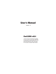
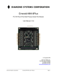
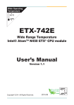
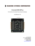
PLUTO SINGLE BOARD COMPUTER
ETX Form-factor Embedded Platform with
Configurable CPU and PC/104-Plus Expansion
Revision
Date
Comment
A3
5/13/14
Updated with new AMD G-Series Pluto models
A4
4/30/15
Updated with new Pluto E3845 models
FOR TECHNICAL SUPPORT
PLEASE CONTACT:
[email protected]
Diamond Part Number 7468050
Copyright 2015
Diamond Systems Corporation
555 Ellis Street.
Mountain View, CA 94043 USA
Tel 1-650-810-2500
Fax 1-650-810-2525
www.diamondsystems.com
CONTENTS
Important Safe-Handling Information .....................................................................................................................3
1. Introduction .......................................................................................................................................................5
1.1 ETX Computer-on-Module (COM) Features .................................................................................................6
1.2 Pluto Baseboard Features .............................................................................................................................6
1.3 Software Compatibility ...................................................................................................................................7
1.4 Thermal Considerations and Heatspreader ..................................................................................................7
2. Functional Overview .........................................................................................................................................8
2.1 Block Diagrams..............................................................................................................................................8
2.2 Baseboard Dimensions .............................................................................................................................. 10
2.3 Baseboard Connectors and Jumpers ......................................................................................................... 11
2.4 Interface Connector Summary.................................................................................................................... 12
2.5 Configuration Jumper Summary ................................................................................................................. 13
3. Getting started ............................................................................................................................................... 14
3.1 Introducing the Pluto Development Kit ....................................................................................................... 14
3.1.1
Pluto Cable Kit ................................................................................................................................... 15
3.2 System Setup ............................................................................................................................................. 16
3.2.1
Display ............................................................................................................................................... 16
3.2.2
Keyboard and Mouse ......................................................................................................................... 16
3.2.3
Mass Storage Devices ....................................................................................................................... 16
3.2.4
Connecting Power .............................................................................................................................. 16
3.2.5
Installing Pluto in an Enclosure .......................................................................................................... 17
3.3 Booting the System .................................................................................................................................... 17
3.3.1
BIOS Setup ........................................................................................................................................ 17
3.3.2
Operating System Drivers .................................................................................................................. 17
4. Interface Connector Details .......................................................................................................................... 18
4.1 PC/104-Plus stacking location (CONA1, PC104+) ..................................................................................... 18
4.1.1
PC/104-Plus ISA Bus (CONA1) ......................................................................................................... 18
4.1.2
PC/104-Plus PCI Bus (PC104+) ........................................................................................................ 20
4.2 USB1-USB4 (USB1, USB2) ....................................................................................................................... 21
4.3 Audio (AUDIO1) .......................................................................................................................................... 21
4.4 Digital I/O (DIO1) ........................................................................................................................................ 21
4.5 CPU Fan Power (FAN1) ............................................................................................................................. 22
4.6 CompactFlash Socket (CFD1) .................................................................................................................... 22
4.7 Ethernet Status LEDs (LANLED1, LANLED2) ........................................................................................... 23
4.8 Ethernet LAN Interfaces (LAN1, LAN2) ...................................................................................................... 23
4.9 IDE (IDE1) .................................................................................................................................................. 24
4.10 Infrared Interface (IR1) ............................................................................................................................... 25
4.11 LCD Inverter Interface (INV1) ..................................................................................................................... 25
4.12 LCD LVDS Out (LVDS1) ............................................................................................................................ 26
4.13 Utility Signals (JFRT1) ................................................................................................................................ 27
4.14 COM2 RS-422/485 Interface (JCOM1) ...................................................................................................... 27
4.15 DC Power Input (PWR1) ............................................................................................................................ 28
4.16 TV Out (TV1) .............................................................................................................................................. 29
4.17 Auxiliary Fan Power (FAN2) ....................................................................................................................... 29
4.18 PS/2 Keyboard and Mouse (KBM1) ........................................................................................................... 29
4.19 Parallel/Floppy (LPT1) ................................................................................................................................ 30
4.20 COM1-COM4 RS-232 (COMA, COMB) ..................................................................................................... 31
4.21 VGA Video Out (VGA1) .............................................................................................................................. 31
4.22 SATA (SATA1, SATA2) .............................................................................................................................. 32
4.23 LPC (LPC1) ................................................................................................................................................ 32
4.24 DDI (DDI1) .................................................................................................................................................. 33
5. Configuration Jumper Details ...................................................................................................................... 34
5.1 CMOS Setup Clear (JBAT1) ....................................................................................................................... 34
5.2 COM2 RS-232/422/485 Mode (JRS2) ........................................................................................................ 34
5.3 CompactFlash IDE Mode (JCFD1) ............................................................................................................. 35
5.4 LCD Panel Voltage Select (JVLCD1) ......................................................................................................... 35
5.5 LCD Backlight Select (JBLON1) ................................................................................................................. 35
5.6 Watchdog Timer Mode (JWT1) .................................................................................................................. 36
Pluto User Manual A4
www.diamondsystems.com
Page 2
IMPORTANT SAFE-HANDLING INFORMATION
WARNING: ESD-Sensitive Electronic Equipment!
Observe ESD-safe handling procedures when working with this product.
Always use this product in a properly grounded work area and wear
appropriate ESD-preventive clothing and/or accessories.
Always store this product in ESD-protective packaging when not in use.
Safe Handling Precautions
Pluto contains numerous I/O connectors that connect to sensitive electronic components. This creates many
opportunities for accidental damage during handling, installation and connection to other equipment. The list here
describes common causes of failure found on boards returned to Diamond Systems for repair. This information is
provided as a source of advice to help you prevent damaging your Diamond (or any vendor’s) embedded
computer boards.
ESD damage – This type of damage is almost impossible to detect, because there is no visual sign of failure or
damage. The symptom is that the board simply stops working, because some component becomes defective.
Usually the failure can be identified and the chip can be replaced.
To prevent ESD damage, always follow proper ESD-prevention practices when handling computer boards.
Damage during handling or storage – On some boards we have noticed physical damage from mishandling. A
common observation is that a screwdriver slipped while installing the board, causing a gouge in the PCB surface
and cutting signal traces or damaging components.
Another common observation is damaged board corners, indicating the board was dropped. This may or may not
cause damage to the circuitry, depending on what is near the corner. Most of our boards are designed with at
least 25 mils clearance between the board edge and any component pad, and ground / power planes are at least
20 mils from the edge to avoid possible shorting from this type of damage. However these design rules are not
sufficient to prevent damage in all situations.
A third cause of failure is when a metal screwdriver tip slips, or a screw drops onto the board while it is powered
on, causing a short between a power pin and a signal pin on a component. This can cause overvoltage / power
supply problems described below. To avoid this type of failure, only perform assembly operations when the
system is powered off.
Sometimes boards are stored in racks with slots that grip the edge of the board. This is a common practice for
board manufacturers. However our boards are generally very dense, and if the board has components very close
to the board edge, they can be damaged or even knocked off the board when the board tilts back in the rack.
Diamond recommends that all our boards be stored only in individual ESD-safe packaging. If multiple boards are
stored together, they should be contained in bins with dividers between boards. Do not pile boards on top of each
other or cram too many boards into a small location. This can cause damage to connector pins or fragile
components.
Power supply wired backwards – Our power supplies and boards are not designed to withstand a reverse
power supply connection. This will destroy each IC that is connected to the power supply. In this case the board
will most likely will be unrepairable and must be replaced. A chip destroyed by reverse power or by excessive
power will often have a visible hole on the top or show some deformation on the top surface due to vaporization
inside the package. Check twice before applying power!
Board not installed properly in PC/104 stack – A common error is to install a PC/104 board accidentally shifted
by 1 row or 1 column. If the board is installed incorrectly, it is possible for power and ground signals on the bus to
make contact with the wrong pins on the board, which can damage the board. For example, this can damage
components attached to the data bus, because it puts the 12V power supply lines directly on data bus lines.
Pluto User Manual A4
www.diamondsystems.com
Page 3
Bent connector pins – This type of problem is often only a cosmetic issue and is easily fixed by bending the pins
back to their proper shape one at a time with needle-nose pliers. The most common cause of bent connector pins
is when a PC/104 board is pulled off the stack by rocking it back and forth left to right, from one end of the
connector to the other. As the board is rocked back and forth it pulls out suddenly, and the pins at the end get
bent significantly. The same situation can occur when pulling a ribbon cable off of a pin header. If the pins are
bent too severely, bending them back can cause them to weaken unacceptably or even break, and the connector
must be replaced.
Pluto User Manual A4
www.diamondsystems.com
Page 4
1. INTRODUCTION
Pluto is a high performance, highly integrated board-level embedded computer matching the footprint of the
popular ETX computer-on-module (COM) standard.
Pluto’s CPU core consists of an ETX CPU module mounted on its bottom side, an approach that improves
thermal management and increases the space for I/O functions and connectors. This innovative design has
enabled Pluto to integrate additional serial and Ethernet controllers, a complete set of peripheral interface header
connectors, and a PC/104-Plus expansion stack location – all within the compact ETX footprint.
Thanks to Pluto’s flexible architecture, you can select from a wide range of ETX-based CPUs to meet each
application’s specific performance, power, and cost requirements. Available processors include the Intel Bay Trail
E3845 CPU and two of the AMD Fusion G-Series CPUs, the T56N and T40N. What’s more, Pluto’s on-board
PC/104-Plus stack location facilitates the addition of custom or off-the-shelf ISA- and PCI-interfaced expansion
modules, helping you satisfy your application’s precise requirements.
Pluto is offered in a range of models that vary according to the choice of ETX CPU module and on-board SODIMM SDRAM capacity.
Pluto Model
ETX CPU
Module
Processor Type
Processor SO-DIMM
Clock
DRAM
Operating
Temperature
PLT-T56N-4G
ETX-T56N-01
AMD Fusion G-T56N
1.65GHz
4GB
-20°C to +71°C
PLT-T56N-2G
ETX-T56N-01
AMD Fusion G-T56N
1.65GHz
2GB
-20°C to +71°C
PLT-T40N-4G
ETX-T40N-01
AMD Fusion G-T40N
1.0GHz
4GB
-20°C to +71°C
PLT-T40N-2G
ETX-T40N-01
AMD Fusion G-T40N
1.0GHz
2GB
-20°C to +71°C
PLT-3845XT-8G ETX-3845-01
Intel E3845 quad core
1.91GHz
8GB
-40°C to +85°C
PLT-3845XT-4G ETX-3845-01
Intel E3845 quad core
1.91GHz
4GB
-40°C to +85°C
Figure 1: Edge View of the Pluto Embedded Platform
Pluto’s features comprise functions provided by the “Pluto baseboard” (top board in stack shown in Figure 1)
along with functions implemented on the attached ETX computer-on-module (COM) macrocomponent (bottom
board in stack), along with a heat-spreader (or heatsink) mounted on the bottom.
Pluto User Manual A4
www.diamondsystems.com
Page 5
1.1
ETX Computer-on-Module (COM) Features
Note: The ETX COM features listed here are typical. Refer to the appropriate ETX CPU
module’s user manual for detailed specifications.
Processor: Choice of AMD Fusion G-Series G-T56N or G-T40N CPUs, or Intel E3845 quad core Bay Trail
CPU
RAM: 200-pin SO-DIMM socket; supports up to 8GB DDR3 SDRAM
Graphics:
VGA CRT interface
LCD flat panel interface (LVDS); provides LCD backlight control signals
TV output
SDVO interface (connector directly on ETX module)
Audio: AC’97 CODEC; mic in, line in/out signals
1 IDE interface:
Supports two devices (Master/Slave)
Usable in PIO or UDMA mode
2 SATA (Serial ATA) interfaces
Support one device each
Connectors directly on ETX COM module
Floppy/parallel port: shared interface
Ethernet interface: 1 10/100Base-T port (Realtek 8103EL)
2 serial ports; 1 RS-232/422/485, 1 RS-232 only
Keyboard/mouse: PS/2 ports; USB also usable for keyboard/mouse
4 USB 2.0 ports
Other: SMbus, IrDA serial interfaces; PC speaker interface; watchdog timer
Dual system expansion buses: 16-bit ISA and 32-bit PCI
ETX 3.0 compliant form-factor (physical and electrical)
1.2
Pluto Baseboard Features
Additional Ethernet interface: 10/100Base-T port (Realtek 8103EL)
2 additional RS-232 serial ports
Digital I/O: 8 logic-level digital inputs and outputs
On-board piezoelectric PC speaker
ATX-style power input and system control
On-board RTC backup battery
ETX COM socket on bottom; conforms to ETX v3.0 specification
I/O connectors provided for all system I/O
On-board CompactFlash socket; configurable as IDE Master or Slave
On-board PC/104-Plus socket; supports ISA and PCI expansion buses
Operating temperature: -20°C to +71°C (-2°F to +160°F) or -40°C to +85°C (-40°F to +185°F)
Form-factor: ETX footprint (4.5 x 3.7 in.)
Pluto User Manual A4
www.diamondsystems.com
Page 6
1.3
Software Compatibility
Pluto’s operating system compatibility is a function of both the Pluto baseboard and the specific ETX CPU module
attached to it. The baseboard and has been qualified for use with Windows XP/XPe and Linux 2.6. The OSes
supported by the ETX CPU module vary according to the specific ETX module used. Consult the appropriate ETX
CPU module’s user manual for details on its OS support.
1.4
Thermal Considerations and Heatspreader
o
o
Pluto models based on the Intel E3845 CPU specified for an operating temperature range of -40 C to +85 C.
o
o
Models with the AMD G-Series CPUs are specified for an operating temperature range of -20 C to +71 C.
Diamond Systems provides a heatspreader attached to Pluto as a conductive cooled thermal layer. However, this
heatspreader by itself does not constitute the complete thermal solution necessary for any specific
implementation, but provides a common interface between the single board computer and the customer’s
implementation-specific thermal solution.
o
The outside surface of the Pluto heatspreader must be kept at a temperature not to exceed +71 C. If your
environment causes the temperature on the outside surface of the heatspreader to exceed the appropriate
temperature, you are responsible for removing the additional heat from the system through either an additional
passive thermal solution or fan solution.
Pluto’s integrated heatspreader makes thermal contact with the heat generating components and provides a flat
surface on the bottom of the assembly for mating to the system enclosure. This technique facilitates efficient
removal of heat from the COM module without the need for a fan. Four mounting holes on the bottom of the
conduction cooled heatspreader are provided to mount Pluto in an enclosure or to a bulkhead. These mounting
holes are #6-32 threaded holes on 2.8" centers.
Pluto User Manual A4
www.diamondsystems.com
Page 7
2. FUNCTIONAL OVERVIEW
2.1
Block Diagrams
Figure 1 shows Pluto’s functional blocks, including circuitry contained on both the Pluto baseboard and the ETX
CPU module. As indicated in the block diagram, the baseboard circuitry primarily comprises interface
connections and additional LAN and serial I/O, while the ETX module integrates the system’s core embedded PC
functionality. Although ETX CPU module processors and precise functions vary between specific modules, the
block diagram of a typical ETX CPU module appears in Figure 3.
IrDA
Figure 2: Pluto Functional Block Diagram
Pluto User Manual A4
www.diamondsystems.com
Page 8
Figure 3: Typical ETX CPU Module Functional Block Diagram
Pluto User Manual A4
www.diamondsystems.com
Page 9
2.2
Baseboard Dimensions
Figure 4 shows the overall dimensions of the Pluto baseboard.
Figure 4: Baseboard Dimensions
Pluto User Manual A4
www.diamondsystems.com
Page 10
2.3
Baseboard Connectors and Jumpers
The diagram in Figure 5 illustrates the position of interface and bus connectors and configuration jumpers located
on the top side of the Pluto baseboard. Pluto’s ETX CPU module plugs into four high-density connectors on the
baseboard’s bottom side, and is secured via screws and standoffs to the baseboard’s four corner mounting holes.
Figure 5: Baseboard Connectors and Jumpers
Pluto User Manual A4
www.diamondsystems.com
Page 11
2.4
Interface Connector Summary
The following table summarizes the functions of Pluto’s interface, utility, and power connectors. The table also
identifies which major subsystem – ETX CPU module or Pluto baseboard – provides the electronics associated
with each connector.
Signal functions relating to all of Pluto’s interface connectors are discussed in greater detail in Section 4 of this
document. Diamond offers an optional Pluto Cable Kit, which provides mating cable assemblies for most of
Pluto’s I/O interface connectors. The table below indicates which of Pluto’s interfaces connectors are supported
by the Pluto Cable Kit.
Interface Function
Connector
Designation
Associated
Subsystem
Supported by
Cable Kit?
Audio
COM1-COM4 RS-232
AUDIO1
COMA, COMB
ETX module
ETX and baseboard
Yes
Yes
COM2 RS-422/485
JCOM1
ETX and baseboard
No
CompactFlash Socket
CFD1
ETX module
n/a
DC Power Input
PWR1
Various
Yes
Digital I/O
DIO1
Pluto baseboard
No
Ethernet LAN Interfaces
LAN1, LAN2
ETX module
Yes
Ethernet Status LEDs
LANLED1, LANLED2 ETX and baseboard
No
Fan Power
FAN1, FAN2
ETX module
No
IDE
IDE1
ETX module
Yes
Infrared Interface
IR1
ETX module
No
LCD Inverter Interface
INV1
Pluto baseboard
No
LCD LVDS Out
LVDS1
ETX module
No
PC/104-Plus ISA bus
CONA1
ETX module
n/a
PC/104-Plus PCI bus
PC104+
ETX module
n/a
Printer/Floppy
LPT1
ETX module
Yes
PS/2 Keyboard/Mouse
KBM1
ETX module
Yes
SATA interfaces
SATA1, SATA2
On ETX module
Yes
Serial Digital Video Output
SDVO
On ETX module
No
TV Out
TV1
ETX module
Yes
USB1-USB4
USB1, USB2
ETX module
Yes
Utility Signals
JFRT1
ETX and baseboard
No
VGA Video Out
VGA1
ETX module
Yes
Pluto User Manual A4
www.diamondsystems.com
Page 12
2.5
Configuration Jumper Summary
The Pluto baseboard’s configuration jumpers are listed below. Details regarding the use of these jumpers appear
in Section 5 of this document.
Jumper
Description
JBAT1
CMOS Setup clear
JRS2
COM2 RS-232/422/485 mode select
JCFD1
CompactFlash IDE mode
JVLCD1
LCD panel voltage select
JWT1
Watchdog timer mode
JBLON1
LCD Backlight select
Pluto User Manual A4
www.diamondsystems.com
Page 13
3. GETTING STARTED
First-time Pluto users normally receive the product as part of Diamond’s Pluto Development Kit, which provides
everything needed to ensure rapid application development. This section of the Pluto User Manual covers basic
hardware setup, power connection, system boot-up, and initial software configuration. After Pluto is up and
running, refer to the later sections of this manual for the detailed hardware and software reference information
needed to adapt the product to specific applications.
Important Safe-Handling Information
WARNING: ESD-Sensitive Electronic Equipment!
Observe ESD-safe handling procedures when working
with this product.
Always use this product in a properly grounded work area
and wear appropriate ESD-preventive clothing and/or
accessories.
Always store this product in ESD-protective packaging
when not in use.
Please refer to page 3 of this manual (“Important Safe-Handling Information”) for further
details.
3.1
Introducing the Pluto Development Kit
The Pluto Development Kit provides everything required for Pluto-based rapid application development. The table
below lists the boards, cables, and other items included in the Development Kit.
Item
Diamond P/N
1
Description
Pluto SBC
2
C-PLT-KIT
Pluto Cable Kit
3
MTG104
PC/104 Mounting Kit
4
DOC-PKG
DSC Documentation Package
5
Pluto User Manual A4
Pluto Quick Start Guide
www.diamondsystems.com
Page 14
3.1.1
Pluto Cable Kit
The Pluto Cable Kit provides convenient access to all of Pluto’s I/O features. The kit’s 15 cable assemblies are
shown in the photo below, and identified in the table that follows.
Note: On each interface cable, the end of the cable connector that has a red wire going to it
should be oriented toward the end of the board connector that is labeled “pin 1” (refer to Figure 3
in Section 2 of this manual for an illustration showing the location and orientation of all of the
Pluto Baseboard’s interface connectors.
Item
Qty
Diamond P/N
Description
Connects to…
1
2
6989007
Dual USB
USB1, USB2
2
1
6989004
Audio in/out
AUDIO1
3
2
6989012
SATA data
ETX module
4
1
6989011
PS/2 keyboard/mouse
KBM1
5
2
6989015
Ethernet RJ-45
LAN1, LAN2
6
2
6989008
Dual serial RS-232
COMA, COMB
7
1
6989006
Parallel
LPT1
8
1
6989010
VGA
VGA1
9
1
6989001
Floppy
LPT1
10
1
6989005
IDE data
IDE1
11
1
6989002
DC power (4-wire)
PWR1
12
1
6989003
DC power (2-wire)
PWR1
Pluto User Manual A4
www.diamondsystems.com
Page 15
3.2
System Setup
This section outlines a simple process for preparing Pluto for first-time operation. Additional details regarding
Pluto’s interface functions and connections may be found in Section 4 of this document (“Interface Connector
Details”) and from the attached ETX CPU module’s user manual.
3.2.1
Display
Pluto provides both VGA monitor and LVDS flat panel display interfaces. Recognizing the complexities
associated with connection to parallel-interfaced flat panels, this quick-start process assumes the use of a
standard VGA-compatible monitor (LCD or CRT). Plug the VGA interface cable into VGA1 on the baseboard, and
connect a VGA-compatible display to the female DB15 connector on its free end.
3.2.2
Keyboard and Mouse
Pluto supports operation using either PS/2- or USB-based keyboard and mouse devices. Plug the desired
interface cable (PS/2 or USB) from the Pluto Cable Kit into the designated connector on the baseboard (KBM1,
USB1, or USB2). Then plug the keyboard and mouse interface cables into the mating connectors on the Pluto
interface cables.
3.2.3
Mass Storage Devices
Next, connect Pluto to IDE or SATA hard drive and CD-ROM drives. Depending on the ETX CPU module
attached to your Pluto boardset, Pluto can operate with a combination of both IDE and SATA drives – both hard
drives and CD-ROMs – and can boot from any of them.
IDE drives -- For IDE drive connection, plug the 40-conductor IDE flat ribbon cable from the Cable Kit into
IDE1 of the Pluto baseboard, and plug the IDE cable’s female connectors into either or both drives’ male data
connectors. If an IDE hard drive is used, jumper the drive as the “Master” IDE device using a jumper block on
the drive (consult the drive’s documentation for details). If a second drive is to be connected to the IDE
interface cable, be sure to jumper it as the IDE “Slave” device.
SATA drives – For SATA drive connection, plug the SATA interface cable from the Cable Kit into one of the
SATA connectors on the ETX CPU module. Refer to the ETX module’s User Manual for details on its SATA
interface support and connector location.
Caution! Be sure the system power supply is disconnected from its
AC power source prior to performing the following step…
3.2.4
Connecting Power
Depending on your Pluto setup’s power requirements, attach the tinned wires of either the 2-wire (+5V only) or 4wire (+5V and +12V) DC power cable assemblies (items 11 and 12) to the power input terminal block (PWR1) on
the baseboard. +12V DC power input is not required by either the Pluto baseboard or the attached ETX CPU
module; it is only needed if required by add-on or external devices, including:
Modules plugged into the PC/104-Plus socket that require +12V from the ISA or PCI buses
An external LCD backlight power supply powered by connector INV1
An auxiliary cooling fan powered with +12V through connector FAN2
External circuitry obtaining +12V power via DIO1 (the Digital I/O port)
Caution! Be sure to connect the 2- and 4-wire baseboard DC cable
assemblies’ yellow wire (+12V) to pin 1, the black wires (ground) to pins 2,
3, and 4, and the red wires (+5VDC) to pins 5 and 6 of PWR1).
Pluto User Manual A4
www.diamondsystems.com
Page 16
After attaching the desired DC power cable (2- or 4-wire) to the Pluto baseboard’s power input terminal block,
plug the power cable’s 4-pin male connectors into the female connector an ATX-style (or equivalent) power
supply’s 5.25-inch disk drive power cable.
Connect additional disk drive power cables from the power supply to the system’s IDE or SATA disk drives.
3.2.5
Installing Pluto in an Enclosure
Install the Pluto single board computer in an enclosure that has an appropriate mounting-hole pattern (2.8”
square).
Pluto’s heatspreader has four #6-32 threaded holes on 2.8” centers for mounting. Select four #6-32 threaded
screws of the proper length and head type to work with your enclosure. Allow a minimum of 0.20” and maximum
of 0.30” screw length for insertion into Pluto’s heatspreader. The total screw length will depend on the thickness
of your enclosure wall.
3.3
Booting the System
Power-up the VGA video monitor. Then power-up the system power supply. Pluto should begin its boot-up
sequence immediately, as evidenced by BIOS messages on the connected VGA display. You can run the BIOS
Setup utility and proceed to install an operating system on the boot drive just as you would on a normal desktop
PC.
Note: This process may vary according to the specific ETX CPU module attached to Pluto’s
bottom side. Please refer to the particular ETX module’s user manual for further details
3.3.1
BIOS Setup
The Pluto ETX CPU module’s BIOS ROM provides a wide range of configuration options. When you power up
Pluto for the first time, you should immediately enter the BIOS “Setup” utility in order to adjust BIOS settings to
match your system’s peripheral devices and other requirements and to configure various other hardware and
software parameters.
Options configurable via Setup typically include:
Number and type of mass storage devices
Boot device priority
Video display type and resolution
IDE, serial, and parallel interface modes and protocols
PCI and PnP configuration
Power management setup
Automatic power-up after LAN connection, RTC alarm, power resumption, etc.
System monitoring and security functions
The precise configuration options available via the BIOS Setup utility – and the specific keystroke sequence
required to launch Setup on power-up – vary according to the specific ETX CPU module attached to the Pluto
Baseboard. Refer to the ETX CPU module’s user manual for further details.
3.3.2
Operating System Drivers
Depending on the operating system to be installed on your Pluto setup, it may be necessary to install software
drivers for on-board interface controllers. The driver requirements (if any) will depend on both the Pluto
Baseboard and the attached ETX CPU module. Drivers for Windows XP and Linux 2.6, if required, are included
on the Software and Documentation CD that is included in the Pluto Development Kit. This software is also
available for download from Diamond’s website.
Pluto User Manual A4
www.diamondsystems.com
Page 17
4. INTERFACE CONNECTOR DETAILS
This section describes the functions associated with the Pluto baseboard’s PC/104-Plus bus expansion stack,
utility, I/O interface, and power connectors in greater detail. Section 3.1.1 contains a list of ready-to-use interface
cables included in Diamond’s Pluto Cable Kit.
Many of the signals present on Pluto’s interface connectors are derived directly from signals on the attached ETX
CPU module’s high density ETX bus connectors. Please refer to the particular ETX module’s user manual for
further details on the definition and utilization of these signals. Additional information on these signals appears in
the ETX 3.0 specification, which is available from the ETX Industrial Group’s website (http://www.etxig.de/specs/specs.php). Also available from that site is the latest ETX Design Guide, which provides further
details on the ETX connector signal functions and interface considerations. Several other relevant specifications
are referenced below.
4.1
PC/104-Plus stacking location (CONA1, PC104+)
These connectors accommodate the addition of either PC/104 (ISA bus only), PC/104-Plus (ISA and PCI buses),
or PCI-104 (PCI bus only) modules on top of the Pluto baseboard. Specifications and other details on all three of
these expansion module standards are available from the website of the PC/104 Consortium
(http://www.pc104.org).
4.1.1
PC/104-Plus ISA Bus (CONA1)
The 64- and 40-pin header connectors in location CONA1 carry the PC/104-Plus expansion stack location’s 104pin ISA bus signals. These signals, generated by Pluto’s ETX CPU module, are essentially identical in function
and signaling to those of the 16-bit PC/AT bus, except for the physical design.
A 64-pin header incorporates the 8-bit “PC bus” connector signals, while a 40-pin header incorporates additional
signals associated with the full 16-bit “PC/AT bus.” The signal names and functions for CONA1 are listed in the
table on the following page.
Note: The Pluto baseboard does not provide a means for supplying -5V or -12V DC power to the
PC/104-Plus ISA bus. Most PC/104 and PC/104-Plus modules do not require these voltages to
be supplied by the bus.
Pluto User Manual A4
www.diamondsystems.com
Page 18
IOCHCHKSD7
SD6
SD5
SD4
SD3
SD2
SD1
SD0
IOCHRDY
AEN
SA19
SA18
SA17
SA16
SA15
SA14
SA13
SA12
SA11
SA10
SA9
SA8
SA7
SA6
SA5
SA4
SA3
SA2
SA1
SA0
GND
A1
A2
A3
A4
A5
A6
A7
A8
A9
A10
A11
A12
A13
A14
A15
A16
A17
A18
A19
A20
A21
A22
A23
A24
A25
A26
A27
A28
A29
A30
A31
A32
Pluto User Manual A4
B1
B2
B3
B4
B5
B6
B7
B8
B9
B10
B11
B12
B13
B14
B15
B16
B17
B18
B19
B20
B21
B22
B23
B24
B25
B26
B27
B28
B29
B30
B31
B32
GND
RESETDRV
+5V
IRQ9
-5V (N/C)
DRQ2
-12V (N/C)
ENDXFR+12V
Key (no pin)
SMEMWSMEMRIOWIORDACK3DRQ3
DACK1DRQ1
REFRESHSYSCLK
IRQ7
IRQ6
IRQ5
IRQ4
IRQ3
DACK2TC
BALE
+5V
OSC
GND
GND
GND
SBHELA23
LA22
LA21
LA20
LA19
LA18
LA17
MEMRMEMWSD8
SD9
SD10
SD11
SD12
SD13
SD14
SD15
Key (no pin)
www.diamondsystems.com
C0
C1
C2
C3
C4
C5
C6
C7
C8
C9
C10
C11
C12
C13
C14
C15
C16
C17
C18
C19
D0
D1
D2
D3
D4
D5
D6
D7
D8
D9
D10
D11
D12
D13
D14
D15
D16
D17
D18
D19
GND
MEMCS16-IOCS16IRQ10
IRQ11
IRQ12
IRQ15
IRQ14
DACK0DRQ0
DACK5DRQ5
DACK6DRQ6
DACK7DRQ7
+5
MASTERGND
GND
Page 19
4.1.2
PC/104-Plus PCI Bus (PC104+)
The Pluto baseboard’s PC/104-Plus PCI expansion bus signals are generated by the ETX CPU module, and are
essentially identical in function and signaling to a normal PC motherboard’s 32-bit PCI bus except for the physical
connector, a 120-pin header (PC104+) arranged as four 30-pin rows.
Note: The Pluto baseboard can supply +3.3V DC at up to 1A to the PC/104-Plus PCI bus.
GND/5.0
V KEY
VI/O
A1
B1
Reserved
A2
B2
AD05
A3
CMD/BE0
GND-
+5V
C1
D1
AD00
AD02
AD01
C2
D2
+5V
B3
GND
AD04
C3
D3
AD03
A4
B4
AD07
GND
C4
D4
AD06
A5
B5
AD09
AD08
C5
D5
GND
AD11
A6
B6
VI/O
AD10
C6
D6
M66EN
AD14
A7
B7
AD13
GND
C7
D7
AD12
+3.3V
A8
B8
CMD/BE1-
AD15
C8
D8
+3.3V
SERR-
A9
B9
GND
SB0-
C9
D9
PAR
GND
A1
0
A1
B1
0
B1
PERR-
+3.3V
LOCK-
D1
0
D1
SDONE
+3.3V
C1
0
C1
1
A1
2
A1
1
B1
2
B1
1
C1
2
C1
1
D1
2
D1
3
A1
4
A1
3
B1
4
B1
3
C1
4
C1
3
D1
4
D1
CMD/BE2-
5
A1
6
A1
5
B1
6
B1
5
C1
6
C1
5
D1
6
D1
AD19
7
A1
8
A1
7
B1
8
B1
7
C1
8
C1
7
D1
8
D1
IDSEL2
9
A2
0
A2
9
B2
0
B2
9
C2
0
C2
9
D2
0
D2
GND
1
A2
2
A2
1
B2
2
B2
1
C2
2
C2
1
D2
2
D2
AD31
3
A2
4
A2
3
B2
4
B2
3
C2
4
C2
3
D2
4
D2
5
A2
6
A2
5
B2
6
B2
5
C2
6
C2
5
D2
6
D2
CLK1
7
A2
8
A2
7
B2
8
B2
7
D2
8
D2
RST-
9
A3
0
9
B3
0
9
D3
0
GND/3.3V Key
STOP+3.3V
FRAMEGND
AD18
AD21
+3.3V
IDSEL0
AD24
GND
AD29
+5V
REQ0GND
GNT1+5V
CLK2
GND
+12V
-12V
Pluto User Manual A4
TRDYGND
GND
IRDY-
AD16
+3.3V
+3.3V
AD17
AD20
GND
AD23
AD22
GND
CMD/BE3
IDSEL1
VI/O
AD26
AD25
+5V
AD28
AD30
GND
GND
REQ1-
REQ2VI/O
+5V
GNT2-
CLK0
GND
+5V
CLK3
INTD-
+5V
INTA-
INTB-
7
C2
8
C2
Reserv
ed
9
C3
0
Reserved
www.diamondsystems.com
GND
DEVSEL+3.3V
GND
+3.3V
IDSEL3
AD27
VI/O
GNT0GND
GND
INTC-
Page 20
4.2
USB1-USB4 (USB1, USB2)
Connectors USB1 and USB2 each provide access to two of Pluto’s four USB 2.0 compatible interface ports. The
two connectors have identical pinouts.
4.3
+5V
1
2
+5V
USBD-
3
4
USBD-
USBD+
5
6
USBD+
GND
7
8
GND
GND
9
10
Key
Audio (AUDIO1)
Connector AUDIO1 provides access to Pluto’s AC’97 stereo audio input and output signals.
4.4
Line in, left
1
2
Line in, right
GND
3
4
GND
Mic input
5
6
(unused)
GND
7
8
GND
Speaker out, left
9
10
Speaker out, right
Digital I/O (DIO1)
Connector DIO1 provides eight digital inputs and eight digital outputs. DIO1’s digital inputs and outputs provide
5V CMOS logic levels. The I/O read (data input) address is 0x200, while the I/O write (data output) address is
0x208. DIO1 pins 19 and 20 can supply up to 1A each of +5V and +12V DC power for use by external circuitry
connected to this port.
Pluto User Manual A4
DO0
1
2
DO1
DO2
3
4
DO3
DO4
5
6
DO5
DO6
7
8
DO7
GND
9
10
GND
DI0
11
12
DI1
DI2
13
14
DI3
DI4
15
16
DI5
DI6
17
18
DI7
+5V
19
20
+12V
www.diamondsystems.com
Page 21
4.5
CPU Fan Power (FAN1)
Connector FAN1 provides +5V DC for powering the ETX module’s optional CPU cooling fan. The power source
for this connector is the Pluto Baseboard’s DC Power input connector.
4.6
1
N/C
2
+5V
3
GND
CompactFlash Socket (CFD1)
Socket CFD1 is a standard 50-pin CompactFlash (CF) Type I/II card socket. This connects to Pluto’s Primary IDE
port in parallel with IDE connector IDE1. A jumper option (JCFD1) configures the CF socket to be the Master or
Slave (default) IDE device.
GND1
D3
D4
D5
D6
D7
CE1
A10
OE
A9
A8
A7
VCC
A6
A5
A4
A3
A2
A1
A0
D0
D1
D2
IOCS16
GND25
Pluto User Manual A4
1
2
3
4
5
6
7
8
9
10
11
12
13
14
15
16
17
18
19
20
21
22
23
24
25
26
27
28
29
30
31
32
33
34
35
36
37
38
39
40
41
42
43
44
45
46
47
48
49
50
(unused)
D11
D12
D13
D14
D15
CE2
(unused)
IORDIOWR(unused)
RDY
VCC
CSEL
(unused)
RESETWAIT
INPACK
REG
ACT_SLV
PDIAG
D8
D9
D10
CD2
www.diamondsystems.com
Page 22
4.7
Ethernet Status LEDs (LANLED1, LANLED2)
Connectors LANLED1 and LANLED2 provide signals for adding optional LAN status LEDs to Pluto’s two
10/100Mbps Ethernet ports. LANLED2 supports the Ethernet controller located on the Pluto Baseboard, while
LANLED1 supports ETX CPU module’s controller. Both connectors have identical pinouts.
4.8
Activity LED-
1
2
Activity LED+
Link LED-
3
4
Link LED+
Ethernet LAN Interfaces (LAN1, LAN2)
Connectors LAN1 and LAN2 carry the data signals from Pluto’s two 10/100Mbps Ethernet interfaces. LAN1 is
associated with the Ethernet controller located on the ETX CPU module, while LAN2 provides the interface to an
Realtek 8103EL controller located on the Pluto Baseboard. Connectors LANLED1 and LANLED2 may optionally
be used for adding LAN status LEDs to either or both Ethernet ports. Connectors LAN1 and LAN2 have identical
pinouts.
Pluto User Manual A4
TX+
1
2
TX-
RX+
3
4
(unused)
(unused)
5
6
RX-
(unused)
7
8
(unused)
GND
9
10
Key
www.diamondsystems.com
Page 23
4.9
IDE (IDE1)
Connector IDE1 carries the Primary IDE port signals from the ETX CPU module. This port can be used for
connection of two drives, configured as IDE Master and Slave, daisy-chained on a single 44-conductor ribbon
cable. The Pluto Baseboard’s CF socket (CFD1), which connects in parallel to this set of signals, can be
configured (via jumper JCFD1) to be either the Master or Slave IDE device.
Note: The signals on this connector’s pins are defined by the attached ETX CPU module. Please
refer to the particular ETX module’s user manual for further details on the definition and utilization
of these signals.
Pluto User Manual A4
RESET#
1
2
GND
DATA7
3
4
DATA8
DATA6
5
6
DATA9
DATA5
7
8
DATA10
DATA4
9
10
DATA11
DATA3
11
12
DATA12
DATA2
13
14
DATA13
DATA1
15
16
DATA14
DATA0
17
18
DATA15
GND
19
20
N/C
DREQ
21
22
GND
IOW#
23
24
GND
IOR#
25
26
GND
IRDY
27
28
IDSEL
ACK#
29
30
GND
IRQ
31
32
N/C
AD1
33
34
ATA66 DETECT
AD0
35
36
AD2
CS#2
37
38
CS#3
ACT#
39
40
GND
+5V
41
42
+5V
GND
43
44
GND
www.diamondsystems.com
Page 24
4.10 Infrared Interface (IR1)
Connector IR1 provides a bidirectional serial data interface for use with an external infrared transceiver.
1
+5V
2
(unused)
3
Receive Data
4
GND
5
Transmit Data
4.11 LCD Inverter Interface (INV1)
Connector INV1 provides +12V and backlight control signals for use with an external LCD panel. The +12V power
supplied to this connector passes through from the Pluto Baseboard’s DC Power input connector (PWR1).
The backlight power on/off pin is controlled by the display controller chip on the attached ETX CPU module,
according to power management control configured via the BIOS Setup and the operating system in use. The
effect of the brightness control signal will vary according to the LCD panel and backlight inverter board being
used.
Note: The control signals (BLON-, BIASON) on this connector’s pins are routed from the attached
ETX CPU module’s ETX3 connector. Please refer to the particular ETX module’s user manual for
further details on the definition and utilization of these signals.
1
+12V
2
GND
3
BLON-
4
BIASON
5
GND
Signal Name
Signal Function
Direction
BLON-
LCD backlight power on/off
Output
BIASON
LCD brightness control
Output
+12V
LCD backlight inverter power
Output
GND
Ground
n/a
Pluto User Manual A4
www.diamondsystems.com
Page 25
4.12 LCD LVDS Out (LVDS1)
Connector LVDS1 provides access to LVDS (low-voltage differential signaling) display interface signals that
originate Pluto’s ETX CPU module. Each clock and data signal consists of a differential pair (e.g. TX1CLK+ and
TX1CLK-). VDD is either +3.3V or +5V, depending on the setting of a configuration jumper (JVLCD1) on the Pluto
Baseboard.
Note: The signals on this connector’s pins are defined by the attached ETX CPU module. Please
refer to the particular ETX module’s user manual for further details on the definition and utilization
of these signals.
Pluto User Manual A4
VDD
2
1
VDD
TX2CLK+
4
3
TX1CLK+
TX2CLK-
6
5
TX1CLK-
GND
8
7
GND
TX2D0+
10
9
TX1D0+
TX2D0-
12
11
TX1D0-
GND
14
13
GND
TX2D1+
16
15
TX1D1+
TX2D1-
18
17
TX1D1-
GND
20
19
GND
TX2D2+
22
21
TX1D2+
TX2D2-
24
23
TX1 D2-
GND
26
25
GND
TX2D3+
28
27
TX1D3+
TX2D3-
30
29
TX1 D3-
www.diamondsystems.com
Page 26
4.13 Utility Signals (JFRT1)
This connector provides interface signals for use with various “front panel” switches and indicators.
RESET+
1
2
RESET-
POWER_LED+
3
4
POWER_LED-
HDD_LED+
5
6
HDD_LED-
SPEAKER+
7
8
SPEAKER-
NC
9
I0
GND
Signal Name
Signal Function
Direction
RESET
Active low reset input; connects to “Power
Good” input on ETX CPU module
Input
POWER_LED
Power on indicator
Output
HDD_LED
HDD access indicator
Output
SPEAKER
PC speaker output (connects in parallel
with onboard buzzer)
Output
4.14 COM2 RS-422/485 Interface (JCOM1)
Connector JCOM1 provides access to the COM2 serial port’s transmit and receive data when the port is
configured for either RS-422 or RS-485 serial protocols. The signals present on each of the connector’s four pins
for these two modes are listed in the table below. COM2’s serial protocol mode is selected using configuration
jumpers located at position JRS2 on the Pluto Baseboard. When the port is configured for RS-232 mode, its
interface appears at connector COMA instead of JCOM1.
Pin
Pluto User Manual A4
RS-422 Mode Signal
RS-485 Mode Signal
1
TX+
DATA+
2
TX-
DATA-
3
RX+
N/C
4
RX-
N/C
www.diamondsystems.com
Page 27
4.15 DC Power Input (PWR1)
Connector PWR1 is a screw-terminal block through which Pluto receives its +5V and +12V DC power. Pluto,
itself, only requires +5V DC input for its operation.
PWR1’s “pass-through” +12V power input is available for use in powering PC/104-Plus modules or other external
peripherals requiring it. It routes to…
The PC/104-Plus socket (IDE1/PC104+), for powering optional add-on modules requiring +12V from the
ISA or PCI bus
The external LCD Inverter connector (INV1), for powering an optional LCD backlight supply
The auxiliary cooling fan connector (FAN2), for powering an optional +12V fan
The Digital I/O port connector (DIO1), for use by optional external circuitry
1
+12V
2
GND
3
GND
4
GND
5
+5V
6
+5V
Signal Name
Signal Function
+5V
+5V DC main input power. Range should be +4.75V to +5.25V DC
measured at this connector
+12V
Pass-through power for +12V powered add-on modules and external
peripherals devices including cooling fans, modules on the PC/104-Plus
stack, and LCD backlight. Range should be +11.9V to +13.5V measured
at this connector.
GND
0-V (ground) power return path.
Pluto User Manual A4
www.diamondsystems.com
Page 28
4.16 TV Out (TV1)
Connector TV1 provides access to the Pluto’s TV Out video signals, which originate on the attached ETX CPU
module. The 6-pin connector supports three modes of operation: Composite Video, S-Video, and Component
Video. The utilization of this connector’s six pins in each of these three modes is tabulated below.
Note: The signals on this connector’s pins are defined by the attached ETX CPU module. Please
refer to the particular ETX module’s user manual for further details on the definition and utilization
of these signals.
Pin
Signal Function when in
Composite Video mode
Signal Function when in
S-Video mode
Signal function when in
Component Video mode
1
CVBS
(unused)
Pb
2
GND
GND
GND
3
(unused)
Luminance
Y
4
GND
GND
GND
5
(unused)
Chrominance
Pr
6
GND
GND
GND
4.17 Auxiliary Fan Power (FAN2)
Connector FAN2 provides power for a fan that operates from +12V DC. This power comes from the Pluto
Baseboard’s DC Power connector.
1
GND
2
+12V
3
(unused)
4.18 PS/2 Keyboard and Mouse (KBM1)
Connector KBM1 provides signals for interfacing with PS/2-compatible keyboard and mouse peripherals. Pluto
can also operate with USB keyboard and/or mouse devices.
Pluto User Manual A4
1
Keyboard data
2
GND
3
Mouse data
4
Keyboard clock
5
+5V out
6
Mouse clock
www.diamondsystems.com
Page 29
4.19 Parallel/Floppy (LPT1)
Connector LPT1 provides access to Pluto’s dual-function parallel/floppy interface. The desired mode (parallel or
floppy) must be configured via a BIOS Setup option; refer to the specific ETX CPU module’s user manual for
initialization details.
The table below lists the signals present on connector LPT1 when configured for the bidirectional parallel port
mode. A custom interface cable (provided in the Pluto Cable Kit) is required for connecting between LPT1 and a
floppy drive when the interface is configured for floppy mode.
Note: The signals on this connector’s pins are defined by the attached ETX CPU module. Please
refer to the particular ETX module’s user manual for further details on the definition and utilization
of these signals.
Pluto User Manual A4
STROBE#
1
14
AFD#
PTD0
2
15
Error#
PTD1
3
16
INIT#
PTD2
4
17
SLIN#
PTD3
5
18
GND
PTD4
6
19
GND
PTD5
7
20
GND
PTD6
8
21
GND
PTD7
9
22
GND
ACK#
10
23
GND
Busy
11
24
GND
PE
12
25
GND
Select
13
26
N/C
www.diamondsystems.com
Page 30
4.20 COM1-COM4 RS-232 (COMA, COMB)
Connectors COMA and COMB each provide access to two of Pluto’s four RS-232 compatible serial ports. COM1
and COM2 are on COMA, while COM3 and COM4 are on COMB. Both connectors have identical pinouts.
COM1, COM3, and COM4 only support RS-232 signaling, whereas COM2 supports RS-232, RS-422, and RS485, under the control of a jumper option at JRS2. When configured for either RS-422 or RS-485, COM2’s serial
interface becomes available at connector JCOM1 (described later).
DCD#1/3
1
2
RXD1/3
TXD1/3
3
4
DTR#1/3
GND
5
6
DSR#1/3
RTS#1/3
7
8
CTS#1 / 3
RI#1 / 3
9
10
N/C
DCD#2/ 4
11
12
RXD2/ 4
TXD2/ 4
13
14
DTR#2/ 4
GND
15
16
DSR#2/ 4
RTS#2/ 4
17
18
CTS#2/ 4
RI#2/ 4
19
20
N/C
4.21 VGA Video Out (VGA1)
Connector VGA1 provides the ETX CPU module’s analog VGA video output signal, for driving a VGA-compatible
CRT or LCD monitor.
Note: The signals on this connector’s pins are defined by the attached ETX CPU module. Please
refer to the particular ETX module’s user manual for further details on the definition and utilization
of these signals.
Pluto User Manual A4
RED
1
2
GREEN
BLUE
3
4
(unused)
GROUND
5
6
GND
GROUND
7
8
GND
(unused)
9
10
GND
(unused)
11
12
VDDAT
HSYNC
13
14
VSYNC
VDCLK
15
16
(unused)
www.diamondsystems.com
Page 31
4.22 SATA (SATA1, SATA2)
Connectors SATA1 and SATA2 are located on the top of the AMD ETX computer-on-module. Both connectors
are industry standard SATA connectors and both have the same pin out as shown below.
1
GND
2
TX+
3
TX-
4
GND
5
RX-
6
RX+
7
GND
4.23 LPC (LPC1)
Connector LPC1 is located on the top of the AMD ETX computer-on-module. It is a Hirose FPC12-14P-P0.5
connector with the pin out as shown below.
Pluto User Manual A4
LAD0
1
2
LAD1
LAD2
3
4
LAD3
GND
5
6
LFRAME#
INT_SERIRQ
7
8
BUF_PLT_RST#
GND
9
10
PCLK_CONN
GND
11
12
GND
+3.3V
13
14
+3.3V
www.diamondsystems.com
Page 32
4.24 DDI (DDI1)
Connector DDI1 is located on the top of the AMD ETX computer-on-module. It is a Hirose FH12-26S-0.5SH
connector with the pin out as shown below.
Pluto User Manual A4
GND
1
2
DDI_TX0+
DDI_TX0-
3
4
GND
DDI_TX1+
5
6
DDI_TX1-
GND
7
8
DDI_TX2+
DDI_TX2-
9
10
GND
DDI_TX3+
11
12
DDI_TX3-
GND
13
14
N/C
DDI_AUX+
15
16
DDI_AUX-
GND
17
18
DDI_HPD
SMB_DAT
19
20
SMB_CLK
GND
21
22
GND
GND
23
24
+3.3V
+3.3V
25
26
+5V
www.diamondsystems.com
Page 33
5. CONFIGURATION JUMPER DETAILS
This section explains the use of several jumper options on the Pluto Baseboard.
5.1
CMOS Setup Clear (JBAT1)
Jumper group JBAT1 provides a means to return the BIOS Setup data to its default state automatically on powerup.
5.2
Setting
Mode
Short 1-2
Keep CMOS (default)
Short 2-3
Clear CMOS
COM2 RS-232/422/485 Mode (JRS2)
Jumper group JRS2 configures Pluto’s COM2 port for RS-232, RS-422, or RS-485 protocol operation. When in
RS-232 mode, COM2’s I/O signals are available at interface connector COMA; when in either RS-422 or RS-485
mode, COM2’s interface appears at connector JCOM1.
Pluto User Manual A4
Pins
RS-232 (default)
RS-422
RS-485
1-2
Short
Open
Open
3-4
Open
Short
Open
5-6
Open
Open
Short
www.diamondsystems.com
Page 34
5.3
CompactFlash IDE Mode (JCFD1)
Jumper group JCFD1 enables configuration the Pluto Baseboard’s CF socket to be either the Primary Master or
Primary Slave IDE device.
The Pluto Baseboard’s CF socket (CFD1) and the IDE connector (IDE1) share the system’s Primary IDE
interface. Therefore only two devices at a time – including a CF card plugged into the CompactFlash socket – can
be connected to the system’s IDE interface, with one configured as Master and the other as Slave. If additional
mass storage peripherals are required, they must be SATA devices connected to the attached ETX CPU
module’s SATA connectors (assuming the ETX module provides SATA support).
Once the system is operational, use the BIOS Setup utility to configure which drive is to be used for booting the
system’s operating system.
5.4
Setting
Mode
Short 1-2
Primary Master
Open
Primary Slave
(default)
LCD Panel Voltage Select (JVLCD1)
Jumper group JVLCD1 must be configured according to the type of LCD panel that will be attached to the Pluto
Baseboard’s LCD panel interface connector (LVDS1).
5.5
Setting
LCD Panel Voltage
Short 1-2
+5V
Short 2-3
+3.3V (default)
LCD Backlight Select (JBLON1)
The LCD panel backlight active mode can be selection by jumper JBLON1 as high or low.
Pluto User Manual A4
www.diamondsystems.com
Page 35
5.6
Watchdog Timer Mode (JWT1)
Jumper group JWT1 determines the behavior of Pluto’s watchdog timer, as indicated in the table below. In the
case of a Reset (2-3 shorted), a watchdog timer time-out condition produces the same effect as pressing the
front-panel reset button (see interface connector PWR1).
Setting
Mode
Short 1-2
Timeout triggers non-maskable interrupt (NMI)
Short 2-3
Timeout triggers system Reset (Default)
Open
Disables watchdog timer
Pluto User Manual A4
www.diamondsystems.com
Page 36