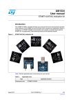
1
PRODUCT MANUAL
AA-09-01
Evolver SE
Robotic Atomizer
MODEL: A12455-XXXXXXXX
IMPORTANT: Before using this equipment,
carefully read SAFETY PRECAUTIONS, starting on
page 1, and all instructions in this manual. Keep
this Service Manual for future reference.
Product Manual Price: $50.00
2
CONTENTS
Section 1: SAFETY
5-9
Safety Precautions
Hazards / Safeguards
Section 2: INTRODUCTION
10-12
Evolver SE
Specifications
Features
Evolver SE Applicator Selection Guide
Section 3: INSTALLATION
13-18
Overview
High Voltage Cable and Tubing (installation)
High Voltage Cable and Tubing (removal)
Changing Gun Head Angle
Paint Mate Robot
Non-Hollow Wrist / Hollow Wrist Conversion
ITW Ransburg REA-III / Evolver SE Conversion Bracket
Evolver SE to 9040 Power Supply Connections
Evolver SE to 9050 Power Supply Connections
Evolver SE to Voltage Master-2 Power Supply Connections
Section 4: OPERATION
19-22
Overview
General Guidelines
Gun Controls
Section 5: MAINTENANCE
23-59
Overview
Routine Maintenance Schedule
Applicator Cleaning
Service Overview
Proper Tools
AA-09-01 : Evolver SE
3
Spray Head Assembly (removal)
Spray Head Disassembly
Spray Head Reassembly
Spray Head Assembly (installation)
Section 6: APPENDIX
60-77
Tool Center Point Drawings
Evolver SE Complete Assembly Parts Identification
Spray Head Assembly Parts Identification
Manifold Assembly Parts Identification
High Voltage Cable Selection Part Identification
Recommended Spare Parts
Repair Kits / Lubricants and Sealers
Troubleshooting Guide
Warranty Policies
AA-09-01 : Evolver SE
4
Section 1: SAFETY
Before operating, maintaining or servicing any ITW Ransburg electrostatic coating system, read and understand all of
the technical and safety literature for your ITW Ransburg products. This manual contains information that is important
for you to know and understand.
This information relates to USER SAFETY and PREVENTING EQUIPMENT PROBLEMS. To help you
recognize this information, we use the following symbols:
CAUTION - states information that tells
how to prevent damage to equipment
or how to avoid a situation that might
cause minor injury.
WARNING - states information to alert
you to a situation that might cause serious injury if instructions are not followed.
While this manual lists standard specifications and service
procedures, some minor deviations may be found between
the literature and your equipment. Differences in local codes
and plant requirements, material delivery requirements, etc.,
make such variations inevitable. Compare this manual with
your system installation drawings and appropriate ITW Ransburg equipment manuals to reconcile such differences.
Careful study and continued use of this manual will provide a
better understanding of the equipment and process, resulting
in more efficient operation, longer trouble-free service and
faster, easier troubleshooting. If you do not have the manuals and safety literature for your Ransburg system, contact
your local ITW Ransburg representative or ITW Ransburg.
WARNING
•
The user MUST read and be familiar with the Safety Section in this manual and the ITW Ransburg
safety literature therein identified.
•
This manual MUST be read and thoroughly understood by ALL personnel who operate , clean or
maintain this equipment! Special care should be taken to ensure that the WARNINGS and safety
requirements for operating and servicing the equipment are followed. The user should be aware of
and adhere to ALL local building and fire codes and ordinances as well as NFPA 33 SAFETY STANDARD, 2009 EDITION, prior to installing, operating, and/or servicing this equipment.
•
The hazards shown on the following pages may occur during normal use of this equipment. Please
read the hazard chart beginning on page 6.
AA-09-01 : Evolver SE
5
AREA
Spray Area
HAZARD
SAFEGUARDS
Fire Hazard
Follow These Guidelines
Improper or inadequate operation and maintenance procedures will cause a fire hazard.
Fire extinguishing equipment must be present in the
spray area and test periodically.
Protection against inadvertent arcing that is
capable of causing fire or explosion is lost if
any safety interlocks are disabled during
operation. Frequent power supply shutdown indicates a problem in the system
requiring correction.
Spray areas must be kept clean to prevent the accumulation of combustible residues.
Smoking must never be allowed in the spray area.
The high voltage supplied to the atomizer must be
turned off prior to cleaning, flushing or maintenance.
When using solvents for cleaning:
•
Those used for equipment flushing should have
flash points equal to or higher than those of the
coating material.
•
Those used for general cleaning must have flash
points above 1000F (37.80C).
Spray booth ventilation must be kept at the rates required by NFPA 33, 2009 Edition, OSHA and local
codes. Ventilation must be maintained during cleaning
operations using flammable or combustible solvents.
Electrostatic arcing must be prevented.
Non-factory replacement parts or unauthorized equipment modifications may cause fire or injury.
If used, a key switch bypass is intended for use only
during setup operations. Production should never be
done with safety interlocks disabled.
Never use equipment for use in waterborne installations to spray solvent based materials.
AA-09-01 : Evolver SE
6
AREA
Spray Area
HAZARD
SAFEGUARDS
Explosion
Follow These Guidelines
Improper or inadequate operation and maintenance procedures may cause an explosion.
Protection against inadvertent arcing that is
capable of causing fire or explosion is lost if
any safety interlocks are disabled during
operation. Frequent power supply shutdown indicates a problem in the system
requiring correction.
Electrostatic arcing MUST be prevented.
All electrical equipment must be located outside Class I
or II, Division 1 or 2 hazardous areas, in accordance
with NFPA 33, 2009 Edition.
Test only in areas free of flammable or combustible
materials.
The current overload sensitivity (if equipped) MUST be
set as described in corresponding section of the equipment manual. Protection against inadvertent arcing
that is capable of causing fire or explosion is lost if the
current overload sensitivity is not properly set. Frequent power shutdown indicates a problem with the
system which requires correction.
Always turn the control panel off prior to flushing, cleaning, or working on spray system equipment.
Ensure that the control panel is interlocked with the
ventilation system and conveyor in accordance with
NFPA 33, 2009 Edition.
Have fire extinguishing equipment readily available and
tested periodically.
Spray Area
Explosion - Incompatible Materials
Follow These Guidelines
Halogenated hydrocarbon solvents for example: methylene chloride and 1,1,1,Trichloroethane are not chemically compatible with the aluminum that might be used in
many system components. The chemical
reaction caused by these solvents reacting
with aluminum can become violent and lead
to an equipment explosion.
Aluminum is widely used in other spray application
equipment - such as material pumps, regulators, triggering valves, etc. Halogenated hydrocarbon solvents
must never be used with aluminum equipment during
spraying, flushing, or cleaning. Read the label or data
sheet for the material you intend to spray. If in doubt
as to whether or not a coating or cleaning material is
compatible, contact your coating supplier. Any other
type of solvent may be used with aluminum equipment.
AA-09-01 : Evolver SE
7
AREA
Spray Area / High Voltage Equipment
HAZARD
SAFEGUARDS
Electrical Discharge
Follow These Guidelines
There is a high voltage device that can induce an electrical charge on ungrounded
objects which is capable of igniting coating
materials.
Inadequate grounding will cause a spark
hazard. A spark can ignite many coating
materials and cause a fire or explosion.
Parts being sprayed must be supported on conveyors
or hangers and be grounded. The resistance between
the part and ground must not exceed 1 mega ohm.
All electrically conductive objects in the spray area, with
the exception of those objects required by the process
to be at high voltage, must be grounded.
Any person working in the spray area must be
grounded.
Unless specifically approved for use in hazardous locations, the power supply and other electrical control
equipment must NOT be used in Class I, Division 1 or 2
locations.
Electrical Equipment
Electrical Discharge
Follow These Guidelines
High voltage equipment is utilized. Arcing
in areas of flammable or combustible materials may occur. Personnel are exposed to
high voltage during operation and maintenance.
All electrical equipment must be located outside Class I
or II, Division 1 or 2 hazardous areas. Refer to NFPA
33, 2009 Edition.
Turn the power supply OFF before working on the
equipment.
Protection against inadvertent arcing that
may cause a fire or explosion is lost if safety
circuits are disabled during operation.
Test only in areas free of flammable or combustible
material.
Frequent power supply shutdown indicates
a problem in the system which requires
correction.
Testing may require high voltage to be on, but only as
instructed.
An electrical arc can ignite coating materials
and cause a fire or explosion.
Production should never be done with the safety circuits disabled.
Before turning the high voltage on, make sure no objects are within the sparking distance.
AA-09-01 : Evolver SE
8
AREA
Toxic Substances
HAZARD
SAFEGUARDS
Mechanical Hazard
Follow These Guidelines
Certain material may be harmful if inhaled,
or if there is contact with the skin.
Follow the requirements of the Material Safety Data
Sheet supplied by the coating manufacturer.
Adequate exhaust must be provided to keep the air free
of accumulations of toxic materials.
Use a mask or respirator whenever there is a chance of
inhaling sprayed materials. The mask must be compatible with the material being sprayed and its concentration. Equipment must be as prescribed by an industrial hygienist or safety expert, and be NIOSH approved.
Robot Work Area
Mechanical Hazard
Follow These Guidelines
Improper use or maintenance can lead to
hazardous conditions, particularly from unexpected robot manipulator movement.
Applicator adjustments or maintenance should be done
after the robot is taken out of service. Do not adjust or
repair the applicator if the robot is operating or standing
ready to start.
Refer to robot operating instructions for the procedures
to take a robot out of service.
Follow all OSHA Lockout / Tagout procedures when
performing any maintenance.
All Areas
Improper / Inadequate Training
Follow These Guidelines
Improper operation or maintenance may
create a hazard.
Personnel must be given training in accordance with
the requirements of NFPA 33, 2009 Edition.
Personnel must be properly trained in the
use of this equipment.
Instructions and safety precautions must understood
prior to using this equipment.
Comply with appropriate codes governing ventilation,
fire protection, operation maintenance, and housekeeping. OSHA references are sections 1910.94 and
1910.107. Also refer to NFPA 33, 2009 Edition and
your insurance company requirements.
AA-09-01 : Evolver SE
9
Section 2: INTRODUCTION
The Evolver SE is an automatic robot mounted spray applicator capable of spraying solvent borne or waterborne coatings electrostatically or non-electrostatically. It incorporates a unique 1/3 turn quick disconnect spray head. The spray
head and valve manifold contain fluid and air passages. All fluid passages contain stainless steel and/or plastic fittings,
compatible with halogenated hydrocarbon solvents.
SPECIFICATIONS - Environmental / Physical
Robot / Mounting Compatibility: All non-hollow and hollow wrist robots, Paint Mate, reciprocator and stationary stands.
Operating Voltage: 85 kV maximum with 9050, 9040 or Voltage Master power supply.
Operating Temperature Range: 55 0F (12.8 °C) to 131 0F (55 °C)
Weight: SE with gun, manifold and bracket = 3.35 lbs (1.52 kg) max.
SE with gun, manifold, dump block and bracket = 3.60 lbs (1.64 kg) max.
Length: Dependent on configuration (see configuration drawings)
Paint Flow Rate: Variable to 500 cc/min.
(depending on viscosity and configuration)
Trigger Response Time: 150 msec. OPEN
220 msec. CLOSED
Operating Air Pressures:
Atomizing Air: 100 psig max. (6.9 bar)
Fan Air: 100 psig max. (6.9 bar)
Trigger Air: 70 psig min. - 100 psig max. (4.8 - 6.9 bar)
Dump Pilot: 70 psig min. - 100 psig max. (4.8 - 6.9 bar)
Operating Fluid Pressure: 100 psig max. (6.9 bar)
Tubing Requirements:
Atomizing Air: 5/16" (8mm) OD Nylon
Fan Air: 5/16" (8mm) OD Nylon
Trigger Air: 5/32" (4mm) OD Nylon
Dump Pilot: 5/32" (4mm) OD Nylon
Fluid (Teflon): 5/16" (8mm) non-shielded
Fluid (optional): 3/8" OD shielded (for waterborne or highly conductive materials)
Dump (Teflon): 5/16" (8mm)
Robot Wrist Movement: Axis 6 limit to 430°
AA-09-01 : Evolver SE
10
FEATURES
The features of the Evolver SE applicator includes:
Quick disconnect spray head.
High quality ITW Ransburg air cap and fluid nozzle.
Dual start, dual pitch air cap retaining ring.
Bleed or non-bleed option.
Internal fan and atomization air control valve, with a mechanically timed trigger sequence.
Adaptable to any robot mounting configuration.
Adjustable angle spray head.
Dump valve version available.
AA-09-01 : Evolver SE
11
EVOLVER SE - APPLICATOR SELECTION GUIDE
AA-09-01 : Evolver SE
12
Section 3: INSTALLATION
This information is intended ONLY to indicate the general installation parameters of this product and, where applicable,
its working relationship to other ITW Ransburg system components in typical use.
Each installation is unique and should be directed by an authorized ITW Ransburg representative or conducted using the
ITW Ransburg installation drawings provided for your particular installation.
High Voltage Cable and Tubing (installation)
1.
Connect the high voltage cable to the body assembly by first
adding a small amount of dielectric grease (NOT petroleum
jelly) to the banana plug end. Fully insert cable until it bottoms out in the plug receptacle. Once fully inserted, place
the red collet lock behind the collet to secure the cable in
place. Gently pull the cable to ensure it is locked securely.
2.
Insert the 5/16" (8mm) or optional 3/8" Teflon paint line into
the compression fitting and tighten securely. Use two
wrenches to prevent fitting from turning. Gently pull on the
tubing to ensure it is secure.
3.
Install the 5/16" (8mm) fan and atomization air tubing into
the collet style fittings. Make sure to push the tubing past
the o-ring. Gently pull on the tubing to ensure it is secure.
4.
Install the 5/32" (4mm) trigger pilot tubing into the collet
style fitting. Make sure to push the tubing past the o-ring.
Gently pull on the tubing to ensure it is secure.
5.
If equipped with dump valve: Install the 5/16" (8mm) dump
line (Teflon) into the compression fitting on the dump block
body. Use two wrenches to prevent fitting from turning.
Gently pull on the tubing to ensure it is secure. Install the
5/32" (4mm) dump pilot tubing into the collet style fitting.
Make sure to push the tubing past the o-ring. Gently pull on
the tubing to ensure it is secure.
AA-09-01 : Evolver SE
13
INSTALLATION (continued)
High Voltage Cable and Tubing (removal)
**Ensure high voltage is turned OFF and pressure in ALL air and
fluid lines are at ZERO.
1.
High voltage cable: Remove red retaining clip. Push down
on the collet and then pull cable straight out.
2.
Air tubing (all): Push down on collet and pull straight out.
3.
Fluid tubing (all): Use two wrenches to prevent the fitting
from turning. Loosen nut and ferrule and remove by hand.
Changing Gun Head Angle
1.
To change the angle of the gun head, the shoulder screws
need to be removed.
2.
Align the threaded holes to the gun head angle position
desired.
3.
Install shoulder screws at tighten to a final torque of 15 lbs/
in (1.69 Nm).
Paint Mate Robot
1.
Typical tubing bundle management consists of wrapping entire bundle with spiral wrap.
2.
Start at approximately 18 inches behind the applicator.
3.
Wrap every 2-3 ft.
4.
Route tubing through the center arm open area.
5.
Secure a strain relief (surgical tubing) from the main support arm and attach to the tubing.
6.
Allow at least 2-3 ft. of slack in tubing at the applicator.
7.
Tubing on wrist rotation should be held to a maximum rotation of 430°.
8.
Cycle program slowly to check for any pinch or catch points.
AA-09-01 : Evolver SE
14
INSTALLATION (continued)
Non-Hollow Wrist / Hollow Wrist Conversion
Conversion from a non-hollow wrist robot configuration to a hollow wrist
robot can be easily done by removing the screws indicated in the above
drawing and simply lifting out the center piece.
ITW Ransburg REA-III / Evolver SE Conversion Bracket
With the optional conversion bracket (see below), the Evolver SE can be
a direct replacement for the ITW Ransburg REA-III gun.
AA-09-01 : Evolver SE
15
INSTALLATION (continued)
Evolver SE to 9040 Power Supply Connections
The below drawing shows the connections between the Evolver SE and the 9040 power supply.
AA-09-01 : Evolver SE
16
INSTALLATION (continued)
Evolver SE to 9050 Power Supply Connections
The below drawing shows the connections between the Evolver SE and the 9050 power supply.
AA-09-01 : Evolver SE
17
INSTALLATION (continued)
Evolver SE to Voltage Master-2 Power Supply Connections
The below drawing shows the connections between the Evolver SE and the Voltage Master-2 power supply.
AA-09-01 : Evolver SE
18
Section 4: OPERATION
WARNING
•
Operators must be fully trained in safe operation of electrostatic equipment. Operators must read all
instructions and safety precautions prior to using this equipment (see NFPA-33).
•
Electrical discharge of a high electrical capacitance fluid/paint system can cause fire or explosion with
some materials. If arcing occurs when a specific coating material is used, turn the system OFF and
verify that the fluid in non-flammable. In these conditions, the system is capable of releasing sufficient electrical and thermal energy to cause ignition of specific hazardous materials in the air.
As with any spray finishing system, operation of the Evolver SE involves properly setting the operating parameters to obtain the best finish quality for the coating material being sprayed while maintaining correct operation
and reliability of the equipment used. Adjustments to operating parameters, which cover spraying, cleaning,
and ON/OFF control, include the following:
•
Coating Materials
•
Fluid Flow Rate Control
•
Fluid Valve / Trigger Control
•
Atomization Air (paint atomization control)
•
Fan Air (pattern control)
•
Electrostatic Voltage
•
Target Distance
AA-09-01 : Evolver SE
19
GENERAL GUIDELINES
Paint Viscosity: The applicator is capable of atomizing paint of most any desired viscosity, however it is recommended
to keep the material viscosity as low as possible. This allows spraying at lower fan and atomization air pressures which
result in less overspray and higher transfer efficiency.
WARNING
•
Most paints and solvents are toxic to a certain degree and flammable or combustible. Use them only
in a well ventilated atmosphere. Use protective equipment as required in the Material Safety Data
Sheet (MSDS) supplied with the substance.
Fluid Flow Rate: Fluid flow is adjusted through the robot PLC by varying the pilot pressure to an exterior fluid regulator.
Fluid pressures from the circulating system may exceed the maximum fluid pressure rating of the Evolver SE applicator.
Because of these high fluid pressures, a manual step-down fluid regulator must be used.
Target Distance: The distance between the applicator tip and the article being painted should be 10-14 inches (0.250.36 meters) when using high voltage. Excessive distance will reduce transfer efficiency and cause wrap back (paint
particles being deposited on the applicator body or the robot arm). At close distances the voltage at the tip of the applicator will be reduced, which decreases the charging effect of the applicator.
WARNING
•
If target distance is less than 8 inches (0.20 meters), an arc could occur.
Electrostatic Voltage: Under no load conditions, the maximum voltage limit for the Evolver SE applicator is 85 kV.
Some painting operations may require different voltage settings to obtain optimum transfer efficiencies. If Faraday cage
areas (narrow or recessed areas) are predominant on the item being painted, a lower voltage setting would aid in coating
these areas. When not spraying, it is recommended to set back voltage 30-40 kV or OFF between target parts. Sometimes, depending on the target carrier spacing, higher setback voltages may be required.
AA-09-01 : Evolver SE
20
EVOLVER SE GUN CONTROLS (Fluid Valve / Trigger)
Trigger and Dump: The fluid valves in the Evolver SE are actuated by an air signal. The air pressure must exceed 70
psi (4.8 bar) to assure proper actuation of the valve. Applying air to the valve actuator turns on the fluid flow for the
valve.
The paint trigger valve controls the paint flow to the applicator. When actuated, paint flows through the valve to the fluid
tube and into the spray head.
The dump valve controls the paint flow through the dump line. When actuated, paint flow is directed to the dump return
line. This provides a method of rapidly removing paint from the incoming line for cleaning and/or color change. Normally
the dump valve is not actuated at the same time as the paint valve since the paint valve is intended to cause the fluid to
flow to the applicator head at the set input pressure.
EVOLVER SE GUN CONTROLS (Air)
Atomization (A) / Fan Air (F): The atomization and fan air are turned on by the trigger line and are controlled by an
internal air valve located in the applicator head. During normal operation with the applicator triggered off, there is a slight
bleed of air through the atomization port. This helps keep the passage clean.
Atomizing Air: Adjustments are made through the robot PLC or a manually adjustable air regulator. The lowest air
pressure required to break up the paint should be used. Lower atomizing air pressures result in less overspray and increased transfer efficiency.
Fan Air: Adjusting the fan air increases or decreases the size of the spray pattern. Increasing pressure increases pattern size. Pattern adjustment should be made to suit the size and shape of the object being painted. This adjustment is
made through the robot PLC or a manually adjustable air regulator.
HVLP Spray: The Evolver SE HVLP models, when properly set-up, are designed to provide maximum transfer efficiency by limiting air cap pressures to 10 psi (0.7 bar). In the U.S., this complies with rules issued by SCAQMD and
other air quality authorities.
NOTE - For HVLP operation (max. 10psi, 0.7 bar cap pressure), DO NOT exceed the air inlet pressure, which was
read at the gun base before tubing manifolds, given as follows:
PSI
(Bar)
CAP #
42
(2.9)
48-1
42
(2.9)
481-1
Air cap pressures (Atomization & Fan) should be set using an air cap test kit. This provides a consistent measurement, so initial settings may be duplicated at any time.
AA-09-01 : Evolver SE
21
EVOLVER SE GUN CONTROLS (Mechanically Timed Trigger)
The mechanically timed trigger of the Evolver SE ensures that the atomization and fan air are ON before paint flows out
of the applicator (see diagram below). The helps prevent the gun from spitting paint from lack of atomization or fan air.
AA-09-01 : Evolver SE
22
Section 5: MAINTENANCE
Good maintenance is essential to safe and productive operation. Schedules should be established by the user, based
on the following general information and observations of the initial production requirements.
The ITW Ransburg maintenance and safety information should be made available to each operator.
Normal fire protection measures are necessary, including proper storage of paints and solvents and the proper disposal
of waste. Ready access to appropriate fire extinguishing equipment is required. For details, consult the appropriate
NFPA safety information, your local fire codes, local painting equipment standards, OSHA requirements, as well as your
insurance carrier's information.
WARNING
•
Unexpected robot movement can be hazardous. Do not adjust or repair the spray applicator when the
robot is operating or waiting to start. The robot must be locked out and tagged out per OSHA.
•
Do not adjust or repair the spray applicator when the power supply is ON. Turn OFF the power supply
and follow OSHA lockout / tagout procedures.
•
Solvents used for equipment flushing must have flash points equal to or greater than the flash point rating of the coating material. Solvents used for general cleaning must have flash point ratings higher than
100 °F (37.8 °C). Refer to the "Solvent Selection Guide" in the Appendix section.
•
Never remove spray applicator head from assembly while it is under pressure.
ROUTINE MAINTENANCE SCHEDULE
Follow these maintenance steps to extend the life of the applicator and ensure efficient operation:
Several Times Daily
1. Inspect the fluid nozzle and electrode wire for paint accumulation. Clean as frequently as necessary. (See "Procedures" in the
"Maintenance" section.)
1
2
Daily (or at Shift Start)
1. Inspect work holders for accumulated coating materials (remove such accumulations if present). Using a Megger, measure the resistance of the work holder to ground (should be less than 1 Mega Ohm).
2. Check that the nozzle assembly is clean and undamaged.
AA-09-01 : Evolver SE
23
ROUTINE MAINTENANCE SCHEDULE (continued)
Shut Down (or at Shift End)
1. Flush the lines and allow the solvent to remain in the lines. (See "Procedures" in the "Maintenance" section.)
2. Wipe the applicator and robot wrist with a cloth and a suitable, clean non-polar solvent.
Weekly
1. Check the entire system for damage, leaks and paint accumulation.
2. Clean the atomizer assembly.
APPLICATOR CLEANING
Cleaning
1. Flush the paint supply line and the applicator paint passages using a solvent which is compatible with the material being sprayed.
Continue to flush until all traces of paint are gone.
2. Turn off the solvent supply, actuate paint push out air at the color changer and trigger the applicator. Allow all of the fluid to drain
from the spray applicator fluid passages.
3. Clean the exterior surfaces of the spray applicator with a solvent soaked rag.
4. Remove end cap. Removing the end cap releases tension on all internal spray head components. Remove needle spring and valve
spring, which are loose after removing the piston cap.
1
1
2
2
3
AA-09-01 : Evolver SE
24
APPLICATOR CLEANING (continued)
CAUTION
•
Never attempt to clean the air cap holes with a wire or other metal object. Doing so may damage the air
cap, resulting in distortion of the spray pattern.
5. Remove the air cap retainer and air cap. Soak in a solvent if necessary. If paint remains in the air cap holes, clean with a toothpick
or similar soft wood object. Air caps are best cleaned in an ultrasonic cleaner.
6. Remove the air cap locator and fluid tip. Clean using a solvent.
1
2
3
4
5
7. Tightly grip the needle and unscrew counter-clockwise to remove the electrode. A short piece of H-2339 tubing (1/4" OD x 0.175"
ID) pressed over the electrode will assist in unscrewing the assembly. If required, use needle nose pliers with masking or duct tape.
Carefully clean with a solvent. Replace any parts that show signs of wear or damage.
1
2
CAUTION
•
If using needle nose pliers to unscrew the electrode, be very careful. Do not grip on the tapered sealing
surface. If the pliers slip, they could damage the tapered sealing surface of the electrode.
8. Remove fluid nozzle by unscrewing counter-clockwise. Inspect o-ring and all passages for build-up or damage. Clean or replace as
necessary. Lubricate and reinsert o-ring into applicator barrel and reinstall fluid nozzle. Torque fluid nozzle to 25 lbs-in (2.82 Nm).
NOTE - There should be a small gap between the fluid nozzle and the applicator barrel after tightening.
1
2
3
AA-09-01 : Evolver SE
25
APPLICATOR CLEANING (continued)
9. After cleaning, insert the front needle back into the spray head assembly. Apply Loctite #222, low strength (purple) thread locker, to
the threads of the tip assembly before reassembly.
REAR
10. Install the electrode.
FRONT
NOTE - The electrode should always be installed and tightened before installing the fluid tip and valve springs.
11. Screw fluid tip back into place. Hand tighten first, then with a small wrench, tighten an additional 30°.
1
2
CAUTION
•
After tightening the fluid tip, always check to see if the proper gap of 1/16" (1.59mm) between the needle
nuts and air valve stem occur, before installing the needle and valve springs back into the head.
AA-09-01 : Evolver SE
26
APPLICATOR CLEANING (continued)
12. Replace air cap locator, air cap, and air cap retainer .
1
2
3
13. Apply a thin film of petroleum jelly to valve and needle springs. Install the springs back into the end cap and the spray head assembly.
1
2
3
14. Screw end cap back on.
1
2
15. Reassembly complete.
AA-09-01 : Evolver SE
27
SERVICE
WARNING
•
Unexpected robot movement can be hazardous. Do not adjust or repair the spray applicator when the
robot is operating or waiting to start. The robot must be locked out and tagged out per OSHA prior to removing the applicator from the robot manifold assembly.
Before performing any work on the spray applicator, always flush the fluid passages and blow dry with push-out air, and
wipe the spray applicator clean. Refer to "Gun Cleaning / Service" in the "Maintenance" section, for instructions on how
to properly clean the spray applicator. Depressurize all fluid and air pressures before removing the applicator from its
manifold. Always work in a clear, clean space to minimize part loss and damage.
WARNING
•
Eye protection should be worn while servicing gun.
CAUTION
•
As the spray head is removed from the valve manifold assembly, a certain amount of residual fluid may
be present. Care must be taken not to allow the fluid to drain into the high voltage terminal rings or air
passages.
NOTE - Disassemble spray head only enough to remove and replace defective parts. For instance, if only replacing the
front electrode it is not necessary to remove the fluid nozzle.
NOTE - To prevent damage, always lubricate the o-rings located on the underside of the spray head.
AA-09-01 : Evolver SE
28
PROPER TOOLS
3/8” drive, in./lbs. torque wrench
Standard hex key set
Combination wrenches:
• 1/4”
Wrenches / Special Tools
• 15/16”
• 11/32”
• 9/16”
• 1-1/8”
• 2-3/8”
Seal carrier tool
Socket for seal carrier tool
Screwdrivers
Flat head screwdrivers
Torque screwdrivers
Sealants
Miscellaneous
Lubricants
Insulators
AA-09-01 : Evolver SE
29
SPRAY HEAD ASSEMBLY (removal)
Step 1
Loosen the spray head retainer:
• Use a 3/16” hex wrench
• Turn clockwise to loosen
1
Step 2
Turn the spray head clockwise and
remove.
2
3
AA-09-01 : Evolver SE
30
SPRAY HEAD DISASSEMBLY
• Spray Head End Cap: 79148-00
• Compression Spring: 17615-00
• Valve Return Spring: 9334-00
1
Step 1
Remove spring tension on the electode / fluid tip by removing the piston
end cap.
2
1
Step 2
Remove the piston and needle return
springs.
AA-09-01 : Evolver SE
31
2
3
SPRAY HEAD DISASSEMBLY (continued)
• Air Cap: 791XX-XX
• Retaining Ring: 79154-00
1
Step 3
Loosen and remove the air cap retaining ring.
2
Step 4
Remove and inspect the air cap:
• Wear
• Material build-up
• Cracks or damage
AA-09-01 : Evolver SE
32
SPRAY HEAD DISASSEMBLY (continued)
• Air Cap Locator: EMF-192
• Fluid Tip: 791XX-XX
1
Step 5
Remove the air cap locator.
2
1
Step 6
Remove and inspect the fluid tip.
2
AA-09-01 : Evolver SE
33
SPRAY HEAD DISASSEMBLY (continued)
• Solvent Proof O-ring: 79001-01
• High Wear Electrode: 70430-01
• Fluid Hole Nozzle: (see Appendix
parts list)
1
Remove the electrode:
• Turn counter-clockwise
Step 7
• Use H-2339 tubing (1/4” OD x 0.175
ID) if necessary
Inspect tapered surface for damage.
2
Wire should be straight and roughly
1/2” long
1
Step 8
Remove and inspect the fluid nozzle.
2
AA-09-01 : Evolver SE
34
SPRAY HEAD DISASSEMBLY (continued)
• Needle Shaft Assembly: 79151-00
• Solvent Proof O-ring: 79001-01
Step 9
Remove the o-ring from the spray
head if it does not come out with the
nozzle.
Step 10
Remove the rear needle assembly.
AA-09-01 : Evolver SE
35
SPRAY HEAD DISASSEMBLY (continued)
• Jam Nut:: 7733-07
• Piston Return Spring: RME-38
• Washer Seal: EMF-7
• Seal: RME-32
Step 11
The fluid seal, seal washer, and seal
spring can now be removed from the
front of the gun.
1
Step 12
Use two 3/8" wrenches to loosen the
air valve adjustment nut and jam nut.
2
3
AA-09-01 : Evolver SE
36
SPRAY HEAD DISASSEMBLY (continued)
• Piston Nut:: 7733-07
• U-cup Piston: RME-38
• Piston Plate: EMF-7
• Air Valve Shaft: RME-32
• Solvent Proof O-rings: 79001-28
79001-29
• Rear Piston Seal Carrier: 79146-00
1
Step 13
Slide the piston assembly out of the
body (use pliers if necessary).
2
1
Step 14
Remove the piston nut.
2
AA-09-01 : Evolver SE
37
SPRAY HEAD DISASSEMBLY (continued)
• Piston Nut:: 7733-07
• U-cup Piston: RME-38
• Piston Plate: EMF-7
• Air Valve Shaft: RME-32
• Solvent Proof O-rings: 79001-28
79001-29
• Rear Piston Seal Carrier: 79146-00
1
Step 15
Remove the piston u-cup from the piston plate.
2
1
Step 16
Remove the o-ring from the air shaft.
2
AA-09-01 : Evolver SE
38
SPRAY HEAD DISASSEMBLY (continued)
• Solvent Proof O-rings: 79001-28
79001-29
• Rear Piston Seal Carrier: 79146-00
1
Step 17
2
Using the seal carrier tool, remove the
seal retainer from the spray head.
3
1
Step 18
Remove the o-ring from the seal retainer.
2
AA-09-01 : Evolver SE
39
SPRAY HEAD DISASSEMBLY (continued)
• Air Valve Bushing: 79143-00
• Solvent Proof O-ring: 79001-01
• Teflon O-ring: 13076-13
1
Step 19
Slide the bushing out of the spray
head. It may require hooking and pulling the bushing out using an Allen
wrench or similar object.
Step 20
Remove the two o-rings from the bushing.
AA-09-01 : Evolver SE
40
2
SPRAY HEAD DISASSEMBLY (continued)
• Rear Seal Carrier: 79172-00
• Solvent Proof O-ring: 79001-06
1
Step 21
Slide the seal carrier out of the spray
head.
2
1
Step 22
Remove the o-ring from the seal carrier.
2
AA-09-01 : Evolver SE
41
SPRAY HEAD DISASSEMBLY (continued)
• Solvent Proof O-ring: 79001-01
• Connector Spring: 79171-00
1
Step 23
Remove the o-ring from the spray
head.
2
1
Step 24
Remove the high voltage contact
spring from the spray head.
2
AA-09-01 : Evolver SE
42
SPRAY HEAD DISASSEMBLY (continued)
• SHCS Screw: 79142-00
• Connection Plug: 79141-00
Step 25
Remove the socket head cap screw
holding the connection plug.
1
Step 26
Remove the connection plug from the
spray head.
2
AA-09-01 : Evolver SE
43
SPRAY HEAD REASSEMBLY
• Conductive Compressible Contact:
14061-09
• SHCS Screw: 79142-00
• Connection Plug: 79141-00
Step 1
Install the conductive sponge (if removed) and the connection plug into
the spray head.
Step 2
Install and tighten the socket head cap
screw:
• Torque the screw to 5 lbs.-in. (0.56
Nm)
AA-09-01 : Evolver SE
44
SPRAY HEAD REASSEMBLY (continued)
• Solvent Proof O-ring: 79001-01
• Connector Spring: 79171-00
1
Step 3
Insert the high voltage contact spring
into the spray head.
2
1
Step 4
Install the o-ring into the spray head:
• Push all of the way to the bottom
• Apply a thin layer of petroleum jelly
to the o-ring
2
AA-09-01 : Evolver SE
45
SPRAY HEAD REASSEMBLY (continued)
1
Step 5
Install the o-ring into the seal carrier:
• Apply a thin layer of petroleum jelly
to the o-ring
2
1
Step 6
Install the seal carrier into the spray
head:
• Push all of the way to the bottom
2
AA-09-01 : Evolver SE
46
SPRAY HEAD REASSEMBLY (continued)
1
Step 7
Install the o-ring into the spray head:
• Push all of the way to the bottom
• Apply a thin layer of petroleum jelly
to the o-ring
Install the two o-rings onto the bushing:
Step 8
• White Teflon o-ring (shuts OFF the
fan air)
• Viton o-ring (keeps fan and atomization air separated)
• Apply a thin layer of petroleum jelly
to the Viton o-ring
AA-09-01 : Evolver SE
47
2
SPRAY HEAD REASSEMBLY (continued)
Step 9
Install the bushing into the spray head.
Step 10
Ensure that the alignment pin is in the
correct position.
AA-09-01 : Evolver SE
48
SPRAY HEAD REASSEMBLY (continued)
1
Step 11
Install the o-ring into the seal retainer.
This o-ring separates cylinder air and
atomization air.
• Apply a thin layer of petroleum jelly
to the o-ring
2
1
Step 12
Using the seal carrier tool, install the
seal retainer into the spray head:
• Torque to 30-35 lbs.-in. (3.4-4.0 Nm)
• If not properly torqued, the atomization and fan air may equalize resulting in lack of fan control.
AA-09-01 : Evolver SE
49
2
SPRAY HEAD REASSEMBLY (continued)
1
Step 13
Install the o-ring onto the air valve
shaft. This o-ring separates fan and
atomization air.
• Apply a thin layer of petroleum jelly
to the o-ring
2
1
Step 14
Insert the piston plate into the piston ucup:
• Will leak trigger air out the vent hole
in the rear cap if bad
2
AA-09-01 : Evolver SE
50
SPRAY HEAD REASSEMBLY (continued)
1
Step 15
Install the piston nut.
2
Step 16
Slide the piston assembly into the
spray head.
AA-09-01 : Evolver SE
51
SPRAY HEAD REASSEMBLY (continued)
• Needle Shaft Assembly: 79151-00
• Solvent Proof O-ring: 79001-01
1
Step 17
Loosely install the air valve adjustment
nut and jam nut onto the needle shaft:
• The air valve adjustment nut should
be approximately flush with the end
of the needle shaft
Step 18
Install the rear needle assembly into
the spray head.
AA-09-01 : Evolver SE
52
2
SPRAY HEAD REASSEMBLY (continued)
• Piston Return Spring: RME-38
• Washer Seal: EMF-7
• Seal: RME-32
Step 19
Install the spring, seal washer, and
fluid seal onto the needle shaft.
Step 20
Install the o-ring into the spray head.
Push the o-ring all the way to the
shoulder.
AA-09-01 : Evolver SE
53
SPRAY HEAD REASSEMBLY (continued)
• Solvent Proof O-ring: 79001-01
• High Wear Electrode: 70430-01
• Fluid Hole Nozzle: (see Appendix
parts list)
1
Install the fluid nozzle:
Step 21
• Torque fluid nozzle to 23-25 lbs.-in.
(2.6-2.8 Nm)
Apply a thin layer of petroleum jelly to
the o-ring and threads on the fluid nozzle assembly.
Step 22
Install the electrode:
• Use low strength thread lock (Loctite
#222)
AA-09-01 : Evolver SE
54
2
SPRAY HEAD REASSEMBLY (continued)
• Air Cap Locator: EMF-192
• Fluid Tip: 791XX-XX
1
Step 23
Install the fluid tip (hand tight plus 30°).
2
1
Step 24
Install the air cap locating ring.
2
AA-09-01 : Evolver SE
55
SPRAY HEAD REASSEMBLY (continued)
• Air Cap: 791XX-XX
• Retaining Ring: 79154-00
1
Step 25
Install the air cap and the air cap retaining ring
2
AA-09-01 : Evolver SE
56
SPRAY HEAD REASSEMBLY (continued)
Step 26
With the electrode seated in the fluid
tip, measure the distance between the
jam nut and the piston assembly.
Step 27
Tighten the air valve adjustment nut to
the jam nut when 1/16" is measured.
Re-check measurement.
This adjustment ensures that atomization and fan air are ON before the fluid
needle is engaged.
AA-09-01 : Evolver SE
57
SPRAY HEAD REASSEMBLY (continued)
• Spray Head End Cap: 79148-00
• Compression Spring: 17615-00
• Valve Return Spring: 9334-00
1
Step 28
2
Install the piston and needle return
springs.
3
1
Step 29
Apply a thin layer of petroleum jelly to
the piston cap threads.
Install the piston cap.
AA-09-01 : Evolver SE
58
2
SPRAY HEAD ASSEMBLY (installation)
Apply dielectric grease into the labyrinth of the spray head.
Step 1
Apply a thin layer dielectric grease
onto the o-rings before installing the
spray head.
1
Step 2
Install the spray head onto the mounting block and turn it (counterclockwise) into position.
2
3
1
Tighten the spray head retainer:
• Use a 3/16" hex wrench
Step 3
• Turn counter-clockwise to tighten
• Do not over-tighten
AA-09-01 : Evolver SE
59
2
Section 8: APPENDIX
TOOL CENTER POINT DRAWINGS
AA-09-01 : Evolver SE
60
TOOL CENTER POINT DRAWINGS (continued)
AA-09-01 : Evolver SE
61
TOOL CENTER POINT DRAWINGS (continued)
AA-09-01 : Evolver SE
62
TOOL CENTER POINT DRAWINGS (continued)
AA-09-01 : Evolver SE
63
TOOL CENTER POINT DRAWINGS (continued)
AA-09-01 : Evolver SE
64
EVOLVER SE COMPLETE ASSEMBLY PARTS IDENTIFICATION
AA-09-01 : Evolver SE
65
EVOLVER SE COMPLETE ASSEMBLY PARTS IDENTIFICATION (continued)
AA-09-01 : Evolver SE
66
EVOLVER SE COMPLETE ASSEMBLY PARTS IDENTIFICATION (continued)
AA-09-01 : Evolver SE
67
SPRAY HEAD ASSEMBLY PARTS IDENTIFICATION
AA-09-01 : Evolver SE
68
SPRAY HEAD ASSEMBLY PARTS IDENTIFICATION Conventional Spray (79138-01)
AA-09-01 : Evolver SE
69
SPRAY HEAD ASSEMBLY PARTS IDENTIFICATION HVLP Spray (79138-02)
AA-09-01 : Evolver SE
70
DUMP MANIFOLD PARTS IDENTIFICATION
AA-09-01 : Evolver SE
71
HIGH VOLTAGE CABLE SELECTION PART IDENTIFICATION
ITW Part Number
Length
A10560-05
5 FT +/-3 IN
A10560-10
10 FT +/-3 IN
A10560-16
16 FT +/-3 IN
A10560-20 (standard with gun assembly)
20 FT +/-3 IN
A10560-25
25 FT +/-3 IN
A10560-35
35 FT +/-3 IN
A10560-50
50 FT +/-3 IN
A10560-75
75 FT +/-3 IN
A10560-100
100 FT +/-3 IN
AA-09-01 : Evolver SE
72
RECOMMENDED SPARE PARTS
Description
Select Option Below
Fluid Tip .042 Orifice (1.07mm)
Fluid Tip .055 Orifice (1.40mm)
Fluid Tip .070 Orifice (1.78mm)
Fluid Tip .027 Orifice (0.71mm)
Fluid Tip .047 Orifice (1.19mm)
Fluid Tip .028 Orifice (0.71mm) HVLP used with 79185-48-1 Air
Cap
Fluid Tip .042 Orifice (1.07mm) HVLP used with 79185-48-1 Air
Cap
Fluid Tip .055 Orifice (1.40mm) HVLP used with 79185-48-1 Air
Cap
Fluid Tip .070 Orifice (1.78mm) HVLP used with 79185-48-1 Air
Cap
Fluid Tip .086 Orifice (2.18mm) HVLP used with 79185-48-1 Air
Cap
Select Option Below
Spray Gun Head- Conventional/ Non-Bleed
Spray Gun Head- HVLP/ Non-Bleed
Spray Gun Head- Conventional Bleed
Spray Gun Head- HVLP Bleed
Part Number
Quantity
Fluid Tip
79140-01
79140-02
79140-03
79140-04
79140-05
1-2
1-2
1-2
1-2
1-2
79182-01
79182-02
79182-03
79182-04
79182-05
Gun Head Complete
79138-01
79138-02
79138-04
79138-05
1-2
1-2
1-2
1-2
1-2
0-1
0-1
0-1
0-1
Select Option Below
Air Cap
Air Cap
Air Cap
Air Cap (HVLP) used with 79182-01, -02, -03 Fluid Tips
Air Cap (HVLP) used with 79182-04, -05, Fluid Tips
Select Option Below
Bushing, Air Valve (non bleed type)
Bushing, Air Valve (bleed type)
Air Cap
79153-65R-1
79196-98-1
79197-63-1
79185-48-1
79186-481-1
Bushing
79143-00
79143-01
Select Option Below
Fluid Nozzle (8 hole High Flow)
Fluid Nozzle (8 hole HVLP)
Fluid Nozzle
EMF-195
79183-00
0-1
0-1
Select Option Below
Electrode (High Wear)
Electrode (non-electrostatic)
Electrode
70430-01
A11218-00)
1-2
1-2
AA-09-01 : Evolver SE
73
1-2
1-2
1-2
1-2
1-2
0-1
0-1
RECOMMENDED SPARE PARTS (continued)
Description
Part Number Quantity
Red Locking Clip
Front Ferrule,3/8" OD Tubing
Back Ferrule, 3/8" OD Tubing
Collet, 8mm
Collet, 6mm
Collet, 10mm
Block, Locking
Nut, Fitting (3/8 tube)
Fitting (3.8 tube to AN)
Spring, Connector
Shaft, Valve Piston
Connector Plug
Locator, Air Cap
Retaining Ring, Tapered
Screw, Retaining
Screw, Nylon
Screw
Screw, modified
Screw
Screw
Square Cut Ring
O-ring, Teflon
O-ring, Solvent Proof
O-ring, Solvent Proof
O-ring, Solvent Proof
O-ring, Solvent Proof
O-ring, Solvent Proof
O-ring, Solvent Proof
O-ring, Solvent Proof
O-Ring, Solvent Proof
Seal, Rear Piston
Piston, U Cup
Seal, Washer
Microvalve (for dump valve version)
A10824-00
EMF-203-05
EMF-202-05
77762-04
77516-04
77762-02
79173-00
A12524
A12523
79171-00
79144-00
79141-00
EMF-192
79154-00
79149-00
79174-00
79142-00
A12511-00
SSF-3130
76566-24C
A10612-00
13076-13
79001-01
79001-04
79001-05
79001-06
79001-28
79001-29
79001-30
79001-31
79146-00
7723-06
EMF-7
78949-00
AA-09-01 : Evolver SE
74
1-2
0-2
0-2
0-1
0-1
0-1
2
0-1
1-2
2
0-1
0-1
0-1
1
2-4
2-4
1
1-2
0-2
1-3
2-4
1
1-2
1-2
1-2
1-2
1-2
1-2
1-2
2
0-1
0-1
1
1
REPAIR KITS / LUBRICANTS AND SEALERS
AA-09-01 : Evolver SE
75
TROUBLESHOOTING GUIDE
General Problem
Fluid does not turn on
Possible Cause
Corrective Action
1. Insufficient trigger pilot air.
1.
Increase to 70 psi minimum.
2. Trigger air tube possibly left disconnected.
2.
Reconnect tubing
3. Trigger air tube is pinched or broken
3.
Check tubing for kinks or damage.
4. Piston seal within applicator spray head is 4.
not in place or there is an extremely tight
fit between the seal and the cylinder wall.
Make sure that the seal is in the proper
position and / or lubricate with a small
amount of petroleum jelly.
5. Replace if damaged (trigger air will leak
5. Piston u-cup is bad.
out of rear cap).
No fluid flow
Continuous fluid flow
Lack of fan air control
1. Clogged fluid nozzle.
1.
2. Plugged fluid inlet.
2. Flush clean.
3. No trigger pilot air.
3. Check trigger air pilot (70 psi min.)
1. Trigger pilot air is not shutting off.
1.
Remove trigger pilot air.
2. Weak or damaged needle spring.
2.
Replace needle spring.
3. Fluid seal is worn or damaged.
3.
Replace fluid seal.
1. Improperly torqued seal retainer.
1.
Torque to 30-35 lbs.-in.
2. Teflon o-ring on bushing is damaged.
2. Replace Teflon o-ring (this shuts off the
fan air).
3. Viton o-ring on bushing is damaged.
Remove, inspect and clean fluid nozzle.
3. Replace Viton o-ring (keeps fan and atomization air separated).
Low or no high voltage
1. High current draw.
1.
Paint resistivity must be > 0.1 M Ohms.
2. Loss of high voltage connection between
power supply and manifold.
2.
Check HV cable connection to manifold.
3. Contact spring damaged.
4. Conductive sponge damaged / removed.
Apply dielectric grease to cable end and
reconnect.
3. Replace contact spring.
4. Replace conductive sponge.
5. Applicator grounding out.
6. Power supply is damaged (refer to specific power supply manual for troubleshooting).
AA-09-01 : Evolver SE
76
5. Clean atomizer externally with non-polar
solvent., check for internal fluid leaks or
internal arcing.
WARRANTY POLICIES
LIMITED WARRANTY
ITW Ransburg will replace of repair without charge any part/or equipment that fails within the specified time (see below)
because of faulty workmanship or material, provided that the equipment has been used and maintained in accordance
with ITW Ransburg's written safety and operating instructions, and has been used under normal operating conditions.
Normal wear items are excluded.
THE USE OF OTHER THAN ITW RANSBURG APPROVED PARTS VOIDS ALL WARRANTIES.
SPARE PARTS: One hundred and eighty (180) days from date of purchase, except for rebuilt parts (any part number
ending in "R") for which the warranty period is ninety (90) days.
EQUIPMENT: When purchased as a complete unit, (i.e. guns, power supplies, control units, etc.), is one (1) year from
date of purchase.
WRAPPING THE APPLICATOR IN PLASTIC WILL VOID THIS WARRANTY.
ITW RANSBURG'S ONLY OBLIGATION UNDER THIS WARRANTY IS TO REPLACE PARTS THAT HAVE FAILED
BECAUSE OF FAULTY WORKMANSHIP OR MATERIALS. THERE ARE NO IMPLIED WARRANTIES NOR WARRANTIES OF EITHER MERCHANTABILITY OR FITNESS FOR A PARTICULAR PURPOSE. ITW RANSBURG ASSUMES NO LIABILITY FOR INJURY, DAMAGE TO PROPERTY OR FOR CONSEQUENTIAL DAMAGES FOR LOSS
OF GOODWILL OR PRODUCTION OR INCOME, WHICH RESULT FROM USE OR MISUSE OF THE EQUIPMENT
BY PURCHASER OR OTHERS.
EXCLUSIONS:
If, in ITW Ransburg's opinion the warranty item in question, or other items damaged by this part was improperly installed,
operated or maintained, ITW Ransburg will assume NO responsibility for repair or replacement of the item or items. The
purchaser, therefore will assume all responsibility for any cost of repair or replacement and service related costs if applicable.
AA-09-01 : Evolver SE
77
Product Manual Price: $50.00 (U.S.)
Manufacturing
1910 North Wayne Street
Angola, Indiana 46703-9100
Telephone: 260-665-8800
Fax: 260-665-8516
Technical Service - Assistance
320 Phillips Ave.
Toledo, Ohio 43612-1493
Telephone (toll free): 800-233-3366
Telephone: 419-470-2021
Fax: 419-470-2040
Technical Support Representatives can direct you to the appropriate telephone number for ordering spare parts.
Form No. AA-09-01
© 2009 Illinois Tool Works, Inc. All rights reserved.
Litho in U.S.A.
Models and specifications subject to change without notice.
06/09
AA-09-01 : Evolver SE
78