1
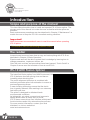
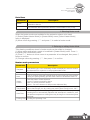
IFS-10
User’s Manual
com
ARC Fusion Splicer
F i b e r O p t i c To o l s a n d S u p p l i e s
IFS-10
Table of Contents
Introduction ......................................................................................................................4
Scope and purpose of the manual .................................................................................4
The reader .........................................................................................................................4
IFS-10 ARC fusion splicer ...............................................................................................4
Chapter 1 - Installation ....................................................................................................5
Safety warnings and precautions ..................................................................................5
Operational safety warnings ..............................................................................................5
Maintenance and external care precautions ......................................................................6
Transport and storage precautions ....................................................................................6
Installation upon delivery ................................................................................................6
Unpacking the splicer .........................................................................................................6
The IFS-10 splicer standard .............................................................................................7
Optional Accessories for IFS-10..........................................................................................7
Overview of external parts ...............................................................................................8
The power connection ......................................................................................................9
General ..............................................................................................................................9
Mounting the power source ..............................................................................................9
The power supply ..........................................................................................................9
General
............................................................................................................................9
Charging the battery.........................................................................................................10
Power source and battery status .....................................................................................11
The heat oven .................................................................................................................12
Chapter 2 - Basic Operation ..........................................................................................13
Quick Guide …………………….......................................................................................13
PAGE 01
IFS-10
INNO Instrument
IFS-10 ARC Fusion Splicer
User’s Manual
Preparing the splicer .....................................................................................................14
Connecting the power supply ..........................................................................................14
Cleaning V-grooves .........................................................................................................14
Cleaning electrodes .........................................................................................................14
Preparing the fiber .........................................................................................................15
How to strip the fiber .......................................................................................................15
How to clean the fiber .....................................................................................................15
How to cleave the fiber ...................................................................................................16
How to make a splice .....................................................................................................17
Inserting the fibers ..........................................................................................................17
Inspecting the fibers ........................................................................................................17
Splicing............................................................................................................................18
How to protect the splice...............................................................................................18
Prepare to move fiber from the splicer to the oven .........................................................18
Moving the fiber to the heat oven ....................................................................................19
Shrinking ........................................................................................................................19
Resetting the fiber movement motors ..........................................................................20
Chapter 3 - Splice programs..........................................................................................21
Splice programs - general .............................................................................................21
Displaying the active splice program................................................................................21
Selecting a splice program...............................................................................................22
Editing a splice program ..................................................................................................22
Connecting the power supply ........................................................................................23
Copying a splice program .............................................................................................23
The steps of the normal splicing process ....................................................................23
Prefusion .........................................................................................................................23
Fusion..............................................................................................................................24
PAGE 02
IFS-10
INNO Instrument
IFS-10 ARC Fusion Splicer
User’s Manual
Summary..........................................................................................................................24
Splice program parameters, normal splicing process ................................................24
Chapter 4 - Other functions & utilities ..........................................................................26
General............................................................................................................................26
Heater Mode ...................................................................................................................26
Selecting Heater Mode ....................................................................................................27
Referring or editing Heater Mode ....................................................................................27
Splice Option ..................................................................................................................28
Data Storage...................................................................................................................29
System Setting................................................................................................................29
Monitor Position ..............................................................................................................30
Power Save .....................................................................................................................31
Maintenance Menu .........................................................................................................32
Replace Electrodes .........................................................................................................32
Stabilizing Electrodes.......................................................................................................33
Diagnostic Test ................................................................................................................33
Dust Check ......................................................................................................................34
Motor Calibration..............................................................................................................34
Arc Calibration .................................................................................................................35
Operation procedure .......................................................................................................35
System Information..........................................................................................................36
PAGE 03
IFS-10
INNO Instrument
IFS-10 ARC Fusion Splicer
User’s Manual
Introduction
Scope and purpose of the manual
This User Manual explains how to install and operate IFS-10 fusion splicer. The
primary goal of this manual is to make the user as familiar with the splicer as
possible.
Basic maintenance procedures are also described in Chapter 6 “Maintenance” to
enable the user to keep the IFS-10 in excellent working condition.
Important!
INNO Instrument recommends all users to read this manual before operating
IFS-10 splicer.
This manual is valid for the following software version:
The reader
Inexperienced users can learn how to carry out basic splicing with IFS-10 as
described in Chapter 2 ‘Basic Operation’.
Experienced users will be able to extend their knowledge by learning how to
change parameters, implement utilities, etc.
Once the main routines and procedures have been learned, “Quick Guide” in
Chapter 2 serves as a fast reminder of how to use IFS-10.
IFS-10 ARC Fusion Splicer
The latest field fusion splicer from INNO Instrument, the
IFS-10 delivers ultra fast splicing time and has an
incredibly short shrinking time.
The profile alignment technique is combined with
extremely accurate splice loss estimation to ensure a
precise alignment process.
A new shrinking technology means that the shrink
time is greatly reduced, thus resulting in an extremely
fast total cycle time.
The splicer is designed to withstand harsh
environmental conditions.
Its lightweight, yet robust, compact and ergonomic
design allows users to easily carry or move.
IFS-10 has a menu-driven user interface with dynamic
function buttons and a fully automatic splice process.
For more product information, contact your local
distributor or visit our website at
www.innoinstrument.com
PAGE 04
IFS-10
INNO Instrument
IFS-10 ARC Fusion Splicer
User’s Manual
Chapter 1 - Installation
Scope and purpose of the manual
This chapter contains the following information:
* Safety warnings and precautions
- operational safety warnings
- maintenance and external care precautions
- transport and storage precautions
* Installation upon delivery
- unpacking the splicer
- removing the cover
* IFS-10 splicer standard delivery kit
- optional accessories
- tool set
* Overview of external parts
* Power connection
- mounting the power source
* Power supply
* Battery
- charging the battery
- power source and battery status
* Heat oven
- mounting the heat oven
Safety warnings and precautions
As IFS-10 is designed for fusion splicing silica glass optical fibers, it is very
important that the splicer should not be used for any other
purpose. The splicer is a precision instrument and must be handled with caution.
Therefore, you must observe the following safety rules and general precautions
regarding the use and handling of IFS-10 at any time.
Operational safety warnings
DO NOT use the splicer in places where there is a risk of explosion.
DO NOT touch the electrodes when the splicer is switched on.
To avoid an electric shock, DO NOT open the back of the splicer or the
power supply. There are no user-serviceable parts inside the splicer, so refer any
service of the splicer to qualified personnel.
Handle the main supply cable carefully. Pull out the cable from the electrical
socket by holding only the wall plug and not by pulling the cable. Always ensure
this cable to be in good condition. Otherwise, there is a risk of fire or electrical
shock.
To prevent any fire or electrical shock, DO NOT expose the splicer to
rain or damp conditions.
Be cautious when handling flammable solvents - always read the
manufacturer’s instructions.
PAGE 05
IFS-10
INNO Instrument
IFS-10 ARC Fusion Splicer
User’s Manual
Maintenance and external care precautions
① Always avoid using hard objects to clean V-grooves and electrodes.
② Always avoid using acetone, thinner, benzol or alcohol when cleaning any part
of the splicer, except for the places advised.
③ Use a dry cloth to remove dust and dirt from the splicer.
④ If the outside of the splicer is dirty, plunge a soft cloth into diluted neutral
washing up liquid, wring out the cloth and clean. Dry the splicer with a dry cloth but
DO NOT use furniture polish or other cleaning agents.
⑤ Always follow the maintenance instructions in this manual.
Transport and storage precautions
① When the splicer is moved from cold to warm environment, you should allow
about an hour for acclimatization. By this time, any condensation should disappear.
② Put the cover on the splicer when it is not in operation.
③ Keep the splicer clean and dry.
④ Always keep the slicer in its carrying case to protect from damage and dirt.
⑤ Always avoid leaving the splicer in direct sunlight or expose to excessive heat.
⑥ Keep the humidity to a minimum level where the splicer is stored. The humidity
must not exceed 95%.
Installation upon delivery
Important!
Follow these instructions carefully.
Unpacking the splicer
Raise the handle upwards and with a firm grip, lift the splicer upward and out of the
carrying case. Place the handle of the splicer downwards.
PAGE 06
IFS-10
INNO Instrument
IFS-10 ARC Fusion Splicer
User’s Manual
IFS-10 Splicer Standard Kit
IFS-10 is delivered in a portable case together with a basic set of tools and this
manual.
① IFS-10 ARC Fusion Splicer
② Plug-in power supply & Battery
③ Carrying case
④ Cooling Tray
⑤ External power supply for the battery charger
⑥ 30W power supply for battery charger & plug-in power cord supply and external
power supply(EU/UK/US)
⑦ VF-78 Cleaver
⑧ E-27 electrode(2 pairs)
⑨ User’s documents(not shown)
1
2
3
4
5
6
7
8
Optional Accessories for IFS-10
① Cooling Tray
② Plug-in Battery
③ VF-78 Cleaver
④ CFS-2 Miller Stripper
PAGE 07
IFS-10
INNO Instrument
IFS-10 ARC Fusion Splicer
User’s Manual
Overview of External Parts
Splicer
Handle
Heat oven
Control buttons (x11)
ON/OFF button
Power supply
/ Battery
Display
USB Terminal
Serial Port
Connector for charging battery
Side
PAGE 08
IFS-10
INNO Instrument
IFS-10 ARC Fusion Splicer
User’s Manual
Power Connection
General
The splicer can be powered from the power supply connected to the main outlet, or
from the battery. In either case, the power source is mounted underneath the
splicer.
Mounting the power source
Insert
Release button
Draw power supply module out
Insert the Battery unit into the power
unit dock until it clicks into place.
Power Supply
General
The power supply connects to a main
outlet through a standard power cable
(1).
A Green LED (2), located behind the
metal grill on the back of the power
supply, is lit when the power supply is in
operation.
PAGE 09
IFS-10
INNO Instrument
IFS-10 ARC Fusion Splicer
User’s Manual
Charging the battery
Charging progress is indicated by five lit LEDs continuously sweeping from 20% to
100% on the battery indicator (see below).
As charging proceeds, one LED is lit when 20% charged. When it’s fully charged,
all five LEDs are lit (i.e. 100%).
100%
80%
60%
40%
Battery Indicator
20%
You can charge the battery in two different ways.
When the battery is detached from the splicer, it can be charged with an external
power supply.
PAGE 10
IFS-10
INNO Instrument
IFS-10 ARC Fusion Splicer
User’s Manual
Charging the battery
Battery Refresh Cycle
If the battery has been charged and
discharged in small amounts over
time, it can be refreshed and the
internal capacity counter updated.
This is achieved by completely
discharging the battery before fully
recharging.
To start this cycle, press and hold
down the PUSH button on the battery
(1) while connecting the power
supply. During the discharge process,
the status LEDs sweep from 100% to
20%. Charging will start when the
battery is fully discharged.
DO NOT cover or touch the battery
during or directly after the refresh
cycle since the metal plate gets very
hot.
2
1
Note:
The battery refresh cycle
can also be started by the
splicer through the “Battery
information and control”
utility
(see Chapter 5 “Other
functions & utilities”).
Power source and battery status
The splicer can be charged in two different ways.
(see step 1 and 2 on the previous page).
The power source which is used to charge the splicer is indicated by a special icon
on the bottom right-hand corner of the monitor (see below)
If the battery is connected to the slicer, then its charging level appears.
If the battery is being used to charge the splicer by the power supply, the charging
level will appear in green color. However, if the charge level drops under 20%, then
the light will appear in red.
<5%
<40-60%
<20%
<60-80%
<20-40%
<80-100%
PAGE 11
IFS-10
INNO Instrument
IFS-10 ARC Fusion Splicer
User’s Manual
Heat oven
1
Heat oven - lid open
Cooling tray
PAGE 12
IFS-10
INNO Instrument
IFS-10 ARC Fusion Splicer
User’s Manual
Chapter 2 - Basic operation
Scope and purpose of the manual
This chapter contains
the following basic information:
- Quick Guide
- Preparing the splicer
- Preparing the fiber
- How to make a splice
- How to check the splice strength
- How to protect the splice
Quick Guide
① Preparing the splicer .....................................14
Connecting the power supply ..............................14
Cleaning V-grooves..............................................14
Cleaning electrodes .............................................14
② Preparing the fiber ........................................15
How to strip the fiber ...........................................15
How to clean the fiber .........................................15
How to cleave the fiber .......................................16
③ How to splice .................................................17
Inserting the fibers ..............................................17
Inspecting the fibers............................................17
Splicing ...............................................................18
④ How to protect the splice ............................18
Moving the fiber to the heat oven .......................19
Shrinking ............................................................19
Resetting the fiber movement motors .........20
PAGE 13
IFS-10
INNO Instrument
IFS-10 ARC Fusion Splicer
User’s Manual
Preparing the splicer
Connecting the power supply
① Connect the splicer to the main by inserting the power cable into the socket on
the left side of power supply of the splicer.
Note:
If the splicer is powered with a fully charged battery, then the main power
supply is not necessary.
② Press the ON/OFF button on the side of the splicer unit on the top left of the
front panel. If the LED becomes green, then the power is on. Press and hold the
ON/OFF button until the LED flashes, then release the button and the splicer will
power off.
Cleaning V-grooves
③ Clean V-grooves, if necessary (A period required)
Cleaning electrodes
④ Check and make sure there are no
fibers within the splicer and close the
safety shield.
⑤ From the Main menu press:
⑥ In the Electrode Care menu, press:
“Confirm”
T 26 C
to clean the electrodes.
See Chapter 5 – “Other functions &
Utilities - Electrode Care” for more
information.
1
Shut Down
3
2
Replace Old Electrodes
Power On
PAGE 14
P 15Kpa
Replace Electrodes
IFS-10
INNO Instrument
IFS-10 ARC Fusion Splicer
User’s Manual
Preparing the fiber
There are three basic preparatory steps to be completed before the fibers can be
placed in the splicer:
- stripping
- cleaning
- cleaving
Note:
Important!
Always remember to slip a
heat-shrinkable sleeve onto either
end of the fibers at the beginning
of each fiber preparations.
Preparing the fibers for splicing is one
of the most important steps in the
splicing process and must be carried
out with the utmost care to minimize
splice loss.
Poorly cleaned and cleaved fibers will
normally result in high splice loss and
low mechanical strength.
How to strip the fiber
① Remove at least 50mm of secondary coating (valid
for both tight and loose tube secondary coating) with
an appropriate stripper (see A, and B).
② Remove approximately 30mm of primary coating
with an appropriate stripper (see C).
How to clean the fiber
Clean bare fibers with a tissue or a pair of cotton
swabs soaked in propanol or ethanol.
Important!
From this point, you must be very careful with the
fibers to ensure that they do not become dirty again.
(For example, avoid putting them down on a dusty
working surface, or even waving them around in the
air). Also check if the V-grooves are clean, if not, wipe
them clean.
PAGE 15
IFS-10
INNO Instrument
IFS-10 ARC Fusion Splicer
User’s Manual
How to cleave the fiber
Cleave the fibers using a high
quality cleaving tool (e.g. INNO
VF-78). Follow the instructions
from the manufacturer’s menu of
the cleaver.
To ensure good splicing, you must
also observe the cleaving lengths
shown below.
Examples of cleaving lengths
Tight secondary coating
Primary coating
≥17mm
≥17mm
Use blue V-grooves
(Clamping on bare fibre)
Fiber preparation checklist
As previously stated preparing the fibers for splicing is one of the most
important factors in the splicing process and must be carried out with the
utmost care to minimize splice loss. Therefore, consult the check-list
backwards to ensure that these steps should be carried out.
Fiber preparation checklist
□The correct V-grooves are selected (See Chapter 6 “Maintenance”)
□The fiber clamps and V-grooves are clean
□A heat-shrink sleeve is in place
□The fibers are stripped
□The fibers are clean
□The end-faces are well-cleaved
□The cleaving lengths are correct
PAGE 16
IFS-10
INNO Instrument
IFS-10 ARC Fusion Splicer
User’s Manual
How to make a splice
Inserting the fibers
① Open the safety shield.
② Raise the fiber clamps.
③ Position the fibers into V-grooves.
Note:
Be careful not to slide the fibers
along V-grooves, but rather
position them over V-grooves and
tilt them down into place.(See
below)
④ Make sure the fiber ends are visible on the monitor. (4a) If the fiber ends are not
visible, the splicer will try to find them by moving the fibers horizontally. The ends
will be found if the fibers are placed within the mechanical movement range of the
horizontal motors (4b). If not, an error message will be displayed.
The splicer will not find fiber ends that are placed above or below the imaging area
(4c). Normally, this should only happen if the V-grooves or the fibers are dirty, or if
the splicer is not well adjusted.
⑤ Clamp the fiber in position by lowering both sets of fiber clamps.
⑥ Close the safety shield.
Inspecting the fibers
① Before continuing with splicing, you should visually
check the fibers in the monitor to make sure they are
clean and well-cleaved.
To change between Front View and Back View, press:
PAGE 17
IFS-10
INNO Instrument
IFS-10 ARC Fusion Splicer
User’s Manual
Front View
Dust on fibre
Chip
Tag
Large cleave
angle
Back View
If you find any defects as
illustrated above, remove the
fibers and prepare again.
Note:
The fibers are checked automatically when you
press ”Splice” button. The splicer automatically
focuses the fibers and checks for damage or
dust particles.
Splicing
① Select any desired splice program (described in detail in Chapter 4 “Splice
programs” – “Selecting a splice program”.
② Splice the fibers by pressing:
Note 2:
The splicer always starts as ”Auto mode”.
The name of the active program appears at the bottom of the display.
How to protect the splice
After splicing, protect the joint by using a heat-shrink sleeve and the heat oven
which is mounted onto the splicer. “Shrink” process can be activated via Main
menu or After Splice menu.
Prepare to move the fiber from the splicer to the oven
① With the spliced fiber still positioned in
the splicer, open the heat oven lid by
sliding it backwards.
① Opening the heat oven lid
PAGE 18
IFS-10
INNO Instrument
IFS-10 ARC Fusion Splicer
User’s Manual
Moving the fiber to the heat oven
① With the spliced fiber still positioned in the splicer, open the heat oven lid by
sliding it backwards.
② Raise left and right fiber clamps on the splicer.
Holding the heat-shrink tube (previously placed onto the fiber), lift the spliced fibers
and holding them taut, move the heat-shrink tube so that it is centered over the
splice point.
③ Move both the fibers and the heat-shrink tube over to the heat oven and place
them in the oven clamps.
Important!
Do not bend either the splice point or the fibers while bringing to the oven. If
necessary, center the heat-shrink sleeve again.
② Lifting and holding the fibers
③ Moving the fibers and heat-shrink
tube to the heat oven
④ Close the heat oven lid.
Shrinking
Heating Mode
⑤ From Main menu (see A) or After Splice menu
(see B), press:
⑥ The oven heats up to “Heater Temperature”
parameter described under “System settings”
utility. (See A)
⑦ Heating continues for the set “Heater Time”
parameter. (See B)
⑧ The oven cools down during the time
specified by “Cooling Time” parameter. (See C)
⑨ When the shrink process is complete, open
the heat oven lid and remove the fiber.
A
B
C
PAGE 19
IFS-10
INNO Instrument
IFS-10 ARC Fusion Splicer
User’s Manual
Note 1:
If no cooling is required, ”cooling time” should be set to zero.
Note 2:
You can stop both heating and cooling by opening the heat oven lid.
Note 3:
The parameters of “Heating temperature”, “heating time” and “ cooling time”
can be adjusted as described under “System settings” utility.
Resetting fiber movement motors
① Remove the fiber from the splice position.
② To return to Main menu and reset the motors (before, during or after heat-shrink
process), press:
The fiber movement motors return to their home positions ready for the next splice.
PAGE 20
IFS-10
INNO Instrument
IFS-10 ARC Fusion Splicer
User’s Manual
Chapter 3 - Splice programs
This chapter contains the following information:
- Splice programs: General
- Displaying an active splice program
- Selecting a splice program
- Editing a splice program
- Creating a new splice
- Editing a splice program name
- Alphanumeric edit
- Changing splice program name
- Steps of splicing
- Splice program parameters
Splice programs - General
IFS-10 has an intuitive and simple, but still very powerful program structure. Splice
programs define arc currents, splice times as well as various parameters used
when performing a splice. Therefore, it is essential to select the correct splice
program in accordance with the type of fiber you want to splice.
There are a number of “pre-defined” splice programs for common fiber
combinations (see below). However, it is also easy to either modify or write new
splice programs to further optimize the parameters for more unusual fiber
combinations. (These are known as “user-defined” programs.)
No. Name
1 Auto
2 MM AUTO
3 SM AUTO
4 DS AUTO
5
6
7
8
9
NZ AUTO
MM CALIBRATION
SM CALIBRATION
DS CALIBRATION
NZ CALIBRATION
List of pre-defined
splice programs
Displaying the active splice program
The active splice program is always displayed at the top of the screen (see below).
The splicer uses this program when you press “confirm” in Main menu:
Splice: Auto
Note:
The active program is always
used when splicing in the manual
mode. However, in this case, both
the automatic focusing and
alignment routines are unable to
use.
Heater: 60mm
Active splice program
Cancel
Menu
Confirm
UP/DN
LT/RT
PAGE 21
IFS-10
INNO Instrument
IFS-10 ARC Fusion Splicer
User’s Manual
Selecting a splice program
To select another splice program other than the active one, you must enter Select
splice mode menu - via Main menu and Splice Mode.
① From Main menu and Splice
Mode, press:
Splice Mode
Splice Mode
Selected Splice Mode appears
on the screen (see A).
② Press Up and Down arrows until
you highlight the program you want
to select.
or
A
③ Press:
“Confirm”
The name of the selected splice
program appears at the top of the
display (see B).
Splice
Program menu
“Confirm”
Note:
You can view, edit and
create new splice programs
without activating them. To
activate a new program, you
must press ”Select”.
B
Editing a splice program
From the Splice Mode menu (shown on previous page) you can access the
parameter editor of the currently highlighted splice program as described below.
Common to all splice programs are program name, process type and parameters all of which are explained in this chapter.
① From Edit Splice Mode menu, press:
“Confirm”
You can edit as it appears on the screen (see A).
PAGE 22
IFS-10
INNO Instrument
IFS-10 ARC Fusion Splicer
User’s Manual
Connecting the power supply
A new splice program is always based upon a copy of an existing program, which
can be either user-defined or pre-defined by INNO instrument.
Should you wish to create a new program for single-mode fibers based on
sensible initial values, then start with a copy of the pre-defined splice program
number 3 “SM_SM”.
Copying a splice program
① Enter Edit Splice Mode menu
( via Main Menu ).
② Highlight an empty space (using up or
down arrows) i.e. the location you want to
copy (see A).
A
Edit Splice Mode
③ Press:
“Confirm”
Note:
You need to make this program
“active” by pressing ”Select”.
Edit Splice Mode
④ Select splice program which you want
to use. Press:
Steps of normal splicing process
This section explains the steps involved in automatic splicing process and
describes how various program parameters are related to this process. The normal
splicing process can be divided into two sections; prefusion and fusion.
Prefusion
During prefusion, the splicer performs automatic alignment and focusing, where the
fibers are subjected to a low prefuse current for cleaning purposes; a prefuse
image is also taken.
At this point, the user is informed of any problems recognized in the prefuse image,
such as a poorly prepared fiber. The splicer will then issue a warning before the
fibers are fused together.
PAGE 23
IFS-10
INNO Instrument
IFS-10 ARC Fusion Splicer
User’s Manual
Preparing the fiber
Fusion
During fusion, the fibers are joined together and subjected to five different currents
as illustrated below. The splicer also takes a number of images during splicing as
illustrated below. These are described in details in Chapter 3 “Evaluating the
splice”.
An important parameter, which changes during splicing, is the distance between
the fibers. During Prefusion, the fibers are apart during Main Current phase, the
fibers are pressed together.
Summary
below
other parameters
important to the splice are
described under “Splice
program parameters” on
the next page.
For a thorough
understanding of the
splicing process, refer to
Chapter 5 “Other
functions & utilities” –
“User settings”, where the
user settings are
explained.Parameters of a
more general nature which can also affect the splice are described in this section.
Splice program parameters, normal splicing process
Parameter
Template
Name
Note
Description
A list of splice modes stored in the splicer database is displayed. Upon inputting the
appropriate mode, the selected splice mode stored in database area is copied to a
selected splice mode in user-programmable area.
Title for a splice mode expressed in up to seven characters.
Detail explanation for a splice mode expressed in up to 15 characters.
Title 2 is displayed at [Splice Mode Select] menu.
Align Type
Sets the aligning method for the fibers.
“Core” : Aligns fibers by core position.
“Clad” : Aligns fibers by center position of the cladding of the fiber.
“Manual” : Aligns fibers manually.
Focus-L
Focus-R
Sets the focal point for fiber observation. The focal point moves closer
to the core when [Focus] value is increased.
"Auto" focus is strongly recommended, as [Focus] optimization is very
difficult. Left and right fibers are focused independently even if they
are a different fiber type (dissimilar fiber splicing). If the fiber core
cannot be observed (e.g. MM fiber), use the “Edge” parameter. [Align]
and [Est. Mode] are automatically fixed to the “Clad” setting. [ECF]
and [Auto Power] are automatically fixed to the "OFF" setting.
Arc Adjust
Pull Test
PAGE 24
Sets to adjust arc power according to the fibers’ conditions.
If [Proof Test] is set to "ON", a pull-test is performed upon opening the
wind protector after splicing or by pressing the SET .
IFS-10
INNO Instrument
IFS-10 ARC Fusion Splicer
User’s Manual
Loss
Estimate
Loss estimate should be regarded as a reference as the estimated splice
loss may not be correct in some cases, depending on the fiber properties.
Minimum
Loss
This amount is added to the estimated splice loss originally calculated.
When splicing specialty or dissimilar fibers, a high actual splice loss may
occur even with optimized arc conditions. To make the actual splice loss
concur with the estimated splice loss, set the minimum value of estimate
to the minimum optimized actual splice loss.
Loss Limit
An error message is displayed if the estimated splice loss exceeds the
selected threshold (loss limit).
Core Angle
Limit
An error message is displayed if the bend angle of the two fibers spliced
exceeds the selected threshold (Core Angle Limit).
Cleave Angle
Limit
An error message is displayed if the cleave angle of either the left or right
fiber ends exceed the selected threshold (cleave limit).
Gap Position
Sets the relative position of the splicing location to the center of
electrodes. Splice loss may be improved in the case of dissimilar fiber
splicing by shifting [Gapset Pos] towards a fiber whose MFD is bigger than
the other fiber MFD.
Gap
Sets the end-face gap between the left and right fibers at the time of
aligning and pre-fusion discharge.
Overlap
Sets the overlap amount of fibers at the fiber stuffing stage. Relatively
small [Overlap] is recommended if [Prefuse Power] is low, while relatively
large [Overlap] is recommended if [Prefuse Power] is high.
Cleaning
Arc Value
A cleaning arc burns out micro dust on the surface of the fiber with an arc
discharge for a short period of time. The duration of the cleaning arc can
be changed by this parameter.
Preheat
Arc Value
Sets the power of the prefuse arc, which is an arc discharge occurring
from the beginning until the fibers begin stuffing. If [Prefuse Power] is set
too low, axial offset may occur if cleaved angles are relatively poor. If
[Prefuse Power] is set too high, fiber end faces are fused excessively and
splice loss gets worse.
Preheat
Arc Time
Sets the duration of the prefuse arc, which is arc discharge occurring from
the beginning until the fibers begin stuffing. Longer [Prefuse Time] is
synonymous with higher [Prefuse Power].
Fuse Arc
Value
Arc discharge can be separated into two stages. Arc1 Power is the first
stage. This sets Arc1 Power.
Fuse Arc
Time
Sets Arc1 time.
Caution If Arc1Time is set 1 sec. or less and Arc2 Power is set to "OFF",
the splice may break during proof-test stage.
PAGE 25
IFS-10
INNO Instrument
IFS-10 ARC Fusion Splicer
User’s Manual
Chapter 4 - Other functions & utilities
-Manual mode
-Electrode care
-Arc check
-Arc counter
-Basic user settings
-Result list setup
-Battery information and control
-Language
-View stored splice results
-Read sensors
-Calibrate motors
-Errors in the system
-Read or change date and time
-Service mode
General
A wide range of tasks that are not considered
part of the basic operation or maintenance of the
splicer can be performed with other functions and
utilities available from Main menu or Utilities
menu.
To gain access to the utilities, from the Main
menu, press:
System Setting
System Info.
In the Utilities menu, the available functions
are listed in the middle. Select a function by
pressing Up and Down arrows. When the function
you want to run is highlighted.
There are also three functions that are available
from the Main menu.
-Arc counter
-Electrode care
-Arc check
The Utilities menu also provides access to the
Manual mode to carry out manual splicing. This is
described in the next section.
Moreover, the Utilities menu provides access to
the Service mode, although this is not described
in details in this manual.
Heater Mode
PAGE 26
IFS-10
INNO Instrument
IFS-10 ARC Fusion Splicer
User’s Manual
Data Base
Parameter
Description
60mm
For standard 60mm protection sleeve, such as INNO FP-03 or FP-03M
protection sleeves.
40mm
For standard 40mm protection sleeves, such as INNO FP-03 (L=40).
1. Selecting Heater mode
Select the heater mode most suitable for the protection sleeve to be used.
(1) Select [Select Heater Mode] in [Heater Mode] menu. [Select Heater Mode]
menu is displayed.
(2) Move cursor by pressing △▽ and press ⊙ to select a heater mode.
2. Referring or editing Heater Mode
Tube-heating conditions stored in heater mode can be edited or changed.
(1) Move cursor and select a mode to be edited in [Heater Mode] menu. Press △
to display [Edit Heat Mode] menu.
(2) Press △▽ buttons to move cursor to a parameter to be changed, then press ⊙
button to confirm.
(3) Change values by pressing △▽, then press ⊙ to confirm.
Heater mode parameters
Parameter
Description
Template
Sets sleeve type. List of all heating modes are displayed. Select a mode in
the list and this is copied to a user-programmable mode.
Name
Title for a heater mode expressed in some characters
Note
Title of a heater mode that is displayed in the lower right part of the monitor
during the splicing/heating process. Max number of characters used is 5.
Heater
Control
Heat
Temperature
Sets the heater control sequence.
Long1: For 60mm protection sleeve.
Mid : For 40mm protection sleeve.
Micro1: For micro sleeves for 900μm outer diameter fiber.
Sets heating temperature. In the case that Ny coated fiber is used with
8mm cleave length, the Ny coating may melt if [Heat Temp] is over 190℃.
Heat Time
Sets heating time from the beginning to the end (cool-down completion).
Heating time is automatically adjusted with atmospheric conditions, such
as ambient temperature. Heating time may be longer or shorter than [Heat
time] set.
Cooling Time
Cooling fan operating Time
PAGE 27
IFS-10
INNO Instrument
IFS-10 ARC Fusion Splicer
User’s Manual
Splice Option
Common parameters for all the modes for splicing and tube heating can be set.
(1) Select [Splice Option] in [Splice Menu] to display [Splice Option] menu.
(2) Select a parameter to be changed.
(3) Press △▽ change values, and press ⊙ to confirm.
Parameter
Description
Auto Start
If “Auto Start” is set to "ON", splicing starts automatically as soon as the
wind protector is closed. Fibers should be prepared and placed into the
splicer in advance.
Pause1
If “Pause1” is set to “ON”, splicing operation pauses when fibers are
forwarded to gap-set position. Cleave angles are displayed during the
pause.
Pause2
If “Pause 2” is set to "ON", splicing operation pauses after fiber alignment
is completed. With ECF “ON”, core-to-core alignment is made after this
pause.
Realign After
Pause2
If “Realign After Pause 2” is set to “ON”, splicing restarts to align fibers
after operated “Pause 2.”
Fiber Image on Screen
Cleave Angle
Loss
Fat
Thin
Setting to “Disable” prevents the splicer from continuing a splice even if
the message “Cleave Angle Error” is disregarded.
Setting to “Disable” prevents the splicer from normally finishing its
operation even if the message “Loss Error,” “Core Angle Error,” “Bubble
Error,” “Fat Error” or “Thin Error” is disregarded.
Ignore Splice Error
Gap set
Pause1
Align
Pause2
Arc
Estimate
PAGE 28
Sets the method of displaying the fiber image on the screen during splicing
operation.
X : Enlarged display of X-axis image
Y : Enlarged display of Y-axis image
X▲▼Y : Composite display vertically of X-axis and Y-axis images
X▲▼Y : Composite display horizontally of X-axis and Y-axis images
X▲Y : Change from Y-axis enlarged image to X-axis enlarged image
during operation
Y▲X : Change from Y-axis enlarged image to X-axis enlarged image
during operation
IFS-10
INNO Instrument
IFS-10 ARC Fusion Splicer
User’s Manual
Data Storage
This splicer stores up to 2,000 splicing results. See [Data Storage] for detail.
Contents of data stored are different depending on splicing mode. No results are
stored for "attenuation splicing".
5-1. Display splice record
Splicing results stored in the memory can be displayed. Comments can be added
or edited.
Note :
* Memory Data can be downloaded By USB Terminal. Consult your nearest
sales agency to learn how.
(1) Select [Data Storage] Menu.
(2) Select [Display Splice Record] and press ⊙ button to display [Data Storage]
Menu.
(3) Select record number by either one of below stated methods. One method is to
move cursor to a specific memory number and press ⊙ . Input a specific memory
number and press ⊙ . Press ⊙ to display the data.
5-2. Delete Splice Record
Splicing results can be cleared by part or whole.
(1) Input specific number (begin-number and end-number) of splicing results to be
cleared by pressing △▽ and ⊙ to enter. Selected splicing results are cleared.
Cleared results are replaced with following splicing results.
Note :
* If [Begin-number] is greater than [End-number], selected splicing results
cannot be cleared. Input appropriate number again.
Clear selected splicing results in memory:
(2) Move cursor to [Clear Splice Record] and press ⊙ to display [Execute Clear
Record].
System Setting
This menu is used to change settings in detail, or for an administrator to limit
functions for operator to select or change.
(1) Press □ in [System Setting] in [Main Menu].
(2) Select a parameter to be changed.
PAGE 29
IFS-10
INNO Instrument
IFS-10 ARC Fusion Splicer
User’s Manual
Parameter
Description
Buzzer
Sets the sound volume of the buzzer
Temperature Unit
Sets the unit of temperature
Language
Sets a language to be displayed on the screen. Select a language to
be displayed.
Monitor Position
Sets the operational direction of splicer. [Front] is for front monitor
operation. [Rear] is for rear monitor operation. Refer to next page for
detail.
Power Save Option
Sets the power saving mode.
Power On Option
Sets the start-up screen image and function. This menu is secured
by password.
Set Calendar
Sets the system time.
Password
Changes the password to access some menus as [Power on
Option] and [Menu Lock].
At the time of shipment from the factory, the password is set as “0”.
If you have forgotten your password after you changed another one,
contact the nearest sales agency.
1. Monitor Position
The splicer is shipped from the factory with settings for the "Monitor Front"
operation style. This can be changed to "Monitor Rear" operation style. The sheath
clamp direction can also be changed for a selected style. When [Monitor Position]
is changed, the direction of the four arrow keys is reversed.
Changing monitor position
(1) Select a monitor position in [Monitor Position]
(2) Change monitor angle.
Monitor Front
Monitor Rear
PAGE 30
IFS-10
INNO Instrument
IFS-10 ARC Fusion Splicer
User’s Manual
(3) Change direction of sheath clamps.
1. Open sheath clamp, loosen and remove screws with a 1.5mm hexagonal
wrench, then remove sheath clamp cover to expose the shaft.
2. Remove the shaft. A paper clip is helpful to remove the shaft, and tweezers are
helpful for holding the shaft.
3. Take sheath clamps off.
4. Reverse direction of sheath clamp, insert shaft and tighten screws.
(4) Turn splicer Power on.
2. Power Save
This function is important for power conservation. If the power saving function is
not set during battery pack use, the number of splice cycles will decrease. The
splicer automatically identifies the type of power supply unit. In addition, it can
program an independent power saving setting. Utilizing these features enables
automatic turning on or off of the power saving function after detecting power
supply units.
Setting Power Save
(1) Insert a power unit and turn on the splicer.
(2) Select [Power Save Option] in [System Setting] menu. [Power Save Option] is
displayed for the type of power supply used.
(3) Change value of [Monitor Shut Down] and [Splicer Shut Down].
Splice Option
Note :
* The value can be changed for power unit used.
Parameter
Descriptions
Monitor Shut Down
Setting this function turns off the power supply to the LCD monitor if
the splicer does not operate after a certain period of time. Always set
this function to a specific shut-down time when using a battery pack.
When the power supply for LCD monitor turns off, the LED near ⊙
key blinks. Press any key to turn on the LCD monitor.
Splicer Shut Down
Automatically turns off the power supply of the splicer if it performs
no operation for a certain period of time. The function serves to
prevent the battery capacity from running low if the splicer is left on
for an extended period of time.
PAGE 31
IFS-10
INNO Instrument
IFS-10 ARC Fusion Splicer
User’s Manual
Maintenance Menu
The splicer has a function to perform routine maintenance. This section describes
how to use the maintenance menu.
(1) Press △▽ to display [Maintenance Menu].
(2) Select a function to perform.
1. Replace Electrode
Electrodes wear out with use and also must be cleaned periodically due to silica
oxide buildup. It is recommended that the electrodes should be replaced after 1,000
arc discharges. When the number of arc discharges reaches a count of 1,000, a
message prompting to replace the electrodes is displayed immediately after turning
on the power. Using the electrodes without a replacement will result in greater
splice loss and reduced splice strength.
Replacement Procedure:
(1) Execute [Replace Electrode] in [Maintenance Menu].
(2) Instruction messages will appear on the screen to turn off the power. Press and
hold ⊙ till the LED color changes from green to red.
(3) Remove the old electrodes.
To remove and replace the electrodes:
(i) Loosen screw located on electrode cover.
(ii) Take electrode out of electrode cover. (Electrode fits into electrode cover)
Loosen the screw
Loosen the screw
Electode
cover
Remove the old electrode.
Install the
new electrode
(4) Clean the new electrodes with alcohol-impregnated clean gauze or lint-free
tissue and install them in the splicer.
(i) Insert the electrode in the electrode cover.
(ii) Place the electrode cover on the splicer and tighten screw.
Tighten the screw
Note :
* Do not pull out wiring when replacing electrode.
* Apply tightening torque of 2kgf-cm when tightening screw to fix electrode
cover.
(5) Turn on the power, prepare and load fibers into the splicer and press ⊙ . After
executing the arc calibration, the splicer will repeat arc discharge 40 times in
succession to stabilize the electrodes.
(6) Upon completion of repeated arc discharge, the splicer executes an arc
calibration again. The user should repeat arc calibration until “Test Finish”
message appears. For details of the arc calibration process.
PAGE 32
IFS-10
INNO Instrument
IFS-10 ARC Fusion Splicer
User’s Manual
2. Stabilizing Electrodes
In the event of sudden change in environmental conditions, etc., the arc power
sometimes becomes unstable, resulting in higher splice loss. Especially when the
splicer is moved from lower altitudes to higher altitudes, it takes time for the arc
power to stabilize. In this case, stabilizing electrodes will expedite the process to
set the arc power stable. If many tests are needed until the “Test OK” message
appears in [Arc Calibration], use this function as well.
Operation Procedure:
(1) Select [Stabilize Electrodes].
(2) Set prepared fibers on V-groove of the splicer for splicing.
(3) Press ⊙ and the splicer begins to stabilize the electrodes in the following ways:
* Repeats short arc discharge five times to measure the arc position.
* Performs [Arc calibration] to calibrate the arc power.
* Perform 40-cycle continuous discharge to stabilize the electrodes.
(4) After completing stabilization, always perform an additional [Arc Calibration].
3. Diagnostic Test
IFS-10 has a built-in diagnostic test feature that allows the user to perform a simple
one step evaluation of splicer performance covering several different critical
variables. Perform this function in case of splicer operation trouble.
Operation Procedure:
(1) Select [Diagnostic Test] in [Maintenance Menu] and execute [Diagnostic Test].
The following checks will be made.
Check Item
Description
1
LED Check
Measures and adjusts the brightness of the illumination LED.
2
Dust Check
Checks the optical path for dust or dirt and judges whether they
disturb fiber observation. If contamination exists, this function
indicates the location.
3
Motor Calibration
Automatically calibrates Press Motor Speed.
4
Arc Calibration
Automatically calibrates the arc power factor and fiber splicing position.
Note :
* Before you start test, remove the fibers from the splicer.
* When the above item No. 2 (dust check) is completed, prepare and load the
fibers into the splicer and press ⊙.
(2) Upon completion of all checks and adjustments, a list of results is displayed. If
the dust check result is not good, clean the objective lenses. If the cleaning cannot
eliminate contamination, there is a possibility that the contamination may have
entered the inside of the optical path. Please contact your nearest sales agency for
additional instructions.
The dust check and Motor Calibration functions exist as independent instructions in
[Maintenance Menu]. It is possible to execute them independently.
PAGE 33
IFS-10
INNO Instrument
IFS-10 ARC Fusion Splicer
User’s Manual
4. Dust Check
The splicer observes fibers through image processing. Dust or contaminants on the
cameras’ lenses and wind protector mirrors disturbs normal observation of fibers
and may result in improper splicing. This function checks the optical path for the
presence or absence of contaminants and judges whether they cause trouble for
fiber splicing.
Operation Procedure:
(1) Select [Dust Check] in [Maintenance Menu].
(2) If fibers are set in the splicer, remove them and press ⊙ again. The splicer
begins the dust check.
(3) The message “Now Checking” is displayed in the middle of the screen. After
observation, the location of contamination judged as a potential problem blinks. If
contamination is discovered, clean the wind protector mirrors and objective lenses
and redo [Dust Check].
(4) Press to finish dust check.
Note :
Even though you have cleaned or replaced the wind protector mirrors, and
have cleaned the objective lenses, but if dirt or dust still remains, please
contact your nearest sales agency.
5. Motor Calibration
Motors are adjusted at the factory before shipping. However, settings can be
changed in various reasons. This function automatically calibrates the speed of all
six motors.
Operation Procedure:
(1) Select [Motor Calibration] in [Maintenance Menu].
(2) Load prepared fibers in the splicer and press ⊙ button.
(3) Speeds for all motors are automatically calibrated. Upon completion,
[Maintenance Menu 2] is displayed.
Note :
* Perform this function when "Fat" or "Thin" error occurs, or fiber aligning or
focusing takes too much time.
PAGE 34
IFS-10
INNO Instrument
IFS-10 ARC Fusion Splicer
User’s Manual
6. Arc Calibration
Atmospheric conditions such as temperature, humidity, and pressure are
constantly changing, which creates variability in the arc temperature. This splicer is
equipped with temperature and pressure sensors that are used in a constant
feedback monitoring control system to regulate the arc power at a constant level.
Changes in arc power due to electrode wear and glass adhesion cannot be
corrected automatically. Also, the center position of arc discharge sometimes shifts
to the left or to the right. In this case, the fiber splicing position has to be shifted in
relation to the arc discharge center. It is necessary to perform an arc power
calibration to eliminate both problems.
Note :
* Arc calibration is performed automatically using [AUTO] mode only. So,
arc calibration does not have to be performed when splicing in this mode.
* Performing [Arc Calibration] function changes the arc power “factor” value.
The factor value is used in the algorithm program for all splicing. The arc
power value will not change in the splice modes.
7. Operation procedure
(1) Select [Arc Calibration] in [Maintenance Menu] to display Arc Calibration on the
screen.
(2) Set prepared fibers on the splicer.
Note :
* Use standard SM or MM fiber for arc calibration.
* Use well-prepared fibers for arc calibration. Dust on the fiber surface
affects arc calibration. For more questions, please contact local sales
agency.
(3) The following is performed after pressing:
1. Arc discharge is performed without fibers on the view screen to detect the center
of arc discharge and adjust the gapset position.
2. Fibers are spliced with an intentional axis offset for arc power calibration.
Note :
* Cleave angle threshold does not link to the parameter "Cleave Limit" in
splicing modes. Cleave angle threshold is independently set for arc
calibration.
3. Axial offset decreases by the surface tension effect when multiple re-arcs are
performed. During the process, the change of axial offset amount is measured and
this is taken into consideration to calibrate arc power.
(4) The calibration result is displayed after completion.
“Test Finished” message:
Arc power and splicing position calibration are successfully completed. Press ⊙ to
exit.
PAGE 35
IFS-10
INNO Instrument
IFS-10 ARC Fusion Splicer
User’s Manual
“Test Again” message:
Arc power and splicing position calibration are completed but further calibration is
strongly recommended, as the change from the previous arc calibration is too
large. Press ⊙ to perform arc calibration, or ⊙ to exit even if arc calibration is not
completed.
8. System Information
Select [System Information]. The following information is displayed.
Parameter
Machine serial number
Software Version
CPLD
FPGA
Current Arc Count
Total Arc Count
Last Maintenance
Next Maintenance
PAGE 36
Description
Displays the serial number of the splicer.
Displays the version number of the software.
Displays the version of CPLD.
Displays the version of FPGA.
Displays the number of arc discharges after electrode
replacement. Performing the function [Replace Electrodes] or
[Arc Count Clear] resets this parameter to zero.
Displays the total number of arc discharges.
Displays the date of last maintenance.
Displays the scheduled date of next maintenance.
----- End of Document -----
PAGE 43