1
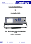
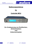
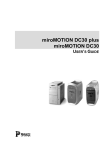
Manual
for
Controller SCU
For the operation of a
Cable Guide Rail
Index
1) General Instructions and Precautions
Page 3
2) Technical Data of Controller SCU
Page 4
3) Connecting to SCU with fibre optic cables
Page 5
4) Menu of SCU
Page 6
5) Moving a Cable Guide Rail
Page 7
6) Menu of Cable Guide Rail
Page 9
7) Trouble Shooting for Controller SCU
Page 11
Appendix:
- Warranty Statement
- Declaration of Conformity
- GPIB-Bus commands
Page 12
Page 13
Page 14
2
1) General Instructions and Precautions
Before this device is applied with power:
Ground it properly through the protective conductor of the power cable to a power source
provided with protective earth contact. Any interruption of the protective (grounding)
conductor, inside or outside the device, or disconnection of the protective earth terminal
could result in personal injury.
The electrical installation of this product must be accomplished by an individual who is
authorized to so do by the appropriate local authority. The installation must be in compliance
with local electrical safety codes.
Only qualified personnel are allowed to operate or service this equipment.
Before making service, contact maturo GmbH
Service or modifications of the device by yourself may void your warranty.
If you attempt to service the unit by yourself, disconnect all electrical power before starting.
There are voltages at many points in the components which could, if contacted, cause
personal injury. Only trained service personnel are allowed to perform adjustments and/or
service procedures upon this device. Capacitors inside this instrument may still be charged
even when instrument is disconnected from its power source.
Stay clear of moving components during the operation of the device.
Do not operate the device while somebody is close to moving parts.
The protection of the area of risk at site is part of the operator.
Read this manual completely before starting installation. This equipment must be installed
and operated only by qualified personnel.
Regularly inspect all equipment and conduct scheduled maintenance in accordance with
the factory recommendations provided. Only use replacement parts and fasteners ordered
directly from the factory.
Information presented enclosed is subject to change as product enhancements are made regularly.
Every effort has been made to ensure that the information in this manual is accurate. However, no
liability or guarantee is assumed for the up-to-dateness, correctness and completeness of the
information provided herein.
Pictures included are for illustration purposes only and do not represent all possible configurations.
3
2) Technical Data of Controller SCU
The Single Control Unit SCU is suited for the operation of one device with one axis of motion.
Those devices are usually used for the operation of turntables, cable guide rails or any other
positioning equipment. This controller SCU permits the operation in manual, semi-automatic
and remote control mode via IEEE 488.2 (GPIB bus) of multiple devices simultaneously.
Technical Data
Data interface
Device interface
Transfer rate
IEEE 488.2 (GPIB-Bus)
CAN-Bus via fibre optic cable
100 baud
Display
4 x 40 characters
Voltage
Current consumption
Fuse
approx.
110-240 VAC, 50/60 Hz, single phase
20W
T 125mA, 250V
Size (W X D)
Height
19” Rack mount (427 x 300 mm)
2 HE (87 mm)
Temperature range
5°C - 40°C
Total weight
5 kg
Accessories
1.5 m power supply cable
Service manual
The multiple control unit SCU works with HP, R&S, and etc. software. The IEEE 488
(GPIB) is available as an interface device.
4
3) Connecting to SCU with fibre optic cables
1. Power of the device and SCU.
2. Connect “IN” at SCU with “OUT” of the device, prefer the red line. Connect “OUT” at
SCU with “IN” of the device, prefer the black line. If your device is prepared for a HCU
(Hand Control Unit), you have to connect the SCU to the port named “SCU”.
3. Power on the device and wait for 30 seconds.
4. Connect the power cable and switch on the power
Attention: Power Consumption: 110-240V, 50/60 Hz, 16A
5. Power on the SCU. While booting the following is shown:
6. When the SCU is ready for working the following MAINSCREEN is shown:
In this example the main screen shows the SCU itself and a not referenced Cable
Guide Rail CGR.
7. With “UP” and “DOWN” you can navigate the arrow “->” between the devices.
5
4) Menu of SCU
1. Navigate the arrow “->” to the SCU and press “ENTER”. Now there is a double arrow
“=>” in front of the SCU. The double arrow “=>” always marks the chosen device
(here SCU).
2. Press “MENU”. The menu screen opens.
With “UP” and “DOWN” you can navigate the arrow.
3. If you want to change the display contrast, go to “display contrast” with the arrow and
press “ENTER”.
4. Change the contrast by pressing “UP” or “DOWN”. When finished press “ENTER” to
confirm, then “EXIT”. You are back in the MAINSCREEN again.
5. For changing the IEEE-address repeat steps 3.1, 3.2 and 3.3, but choose “IEEEaddress”.
6. Change the address with “UP” or “DOWN” and confirm with “ENTER”. Quit with
“EXIT”, the MAINSCREEN is shown again
6
5) Moving a Cable Guide Rail
1. Navigate the arrow in the MAINSCREEN with “UP” or “DOWN” to the Gable Guide
Rail and press “ENTER”. The double arrow marks him now as chosen device.
2. Press “REFERENCE”,
Then “ENTER”. The Guide Rail is now slowly moving to his reference point,
0.00 m.
3. When referencing is finished you will be able to move the Guide Rail manually with
the “UP” and “DOWN” buttons or by entering a new position.
Note: You must make a reference process if the Guide Rail shows “not referenced”,
Referencing is also possible when the Guide Rail is at a defined position.
4. Press “UP” and hold it, the Guide Rail will move, but only up to the maximum limit of
5.40 m. Press “DOWN” and hold it, the Guide Rail will move, but only up to the
minimum limit of 0.00 m.
5. To move to a defined position press “ENTER”,
7
Input the new position, e.g. 2.50.
Press “ENTER” again. The Guide Rail will move to the new position.
6. By pressing the “STOP” button while the Guide Rail is moving, the movement can be
stopped.
8
6) Menu of Guide Rail
1. When a Guide Rail is chosen (double arrow =>) by pressing “MENU” you will enter
the Guide Rail menu. With “UP” and “DOWN” you can navigate to the individual
points.
2. Navigate to “information” and press “ENTER”. The device type, the serial number and
the firmware version will be shown.
It is not possible to make any changes there.
Press “EXIT” and you will be back in the MAINSCREEN.
3. Go to the Guide Rail menu again as explained in D1; navigate to “movement limits”
and press, “ENTER”. The first two lines are the hardware limits of 5.40 m and 0.00 m.
It is not possible to change these hardware limits.
4. Standard for the user limits is “no”.
You can type in user limits and confirm with “ENTER”. With “UP” and “DOWN” you
can navigate between user limit maximum and minimum.
5. To delete a user limit navigate to the according, input a higher (or lower) limit and
confirm with “ENTER”. Repeat this with the second user limit. Press “EXIT” to go back
to the MAINSCREN.
9
6. Go to the Guide Rail menu again as explained in 6.1; navigate to “positioning speed”
and press, “ENTER”. You will see the possible minimal and maximal speed.
You can change the actual speed by type in a value and confirm with “ENTER”.
Press “EXIT” to go back to the MAINSCREEN.
10
7) Trouble Shooting for Controller SCU
If there are problems with the controller, please always carry out the following first:
1. Check power supply – must be between 110V and 240V
2. Check both fuses at the backside of the controller
3. Check user limits and remove the limits, if not in use (see manual for controller)
4. Check fibre optic cables and connections (if possible change cables from a different
device and check)
5. Use a short cable for connection directly to the device in the chamber
6. Disconnect the power supply of the device and the controller for approx. 1 minute;
reconnect the power supply and carry out referencing
Fault
Probable Cause
Suggested Remedy
Display does not light
up
• LCD display not connected properly
or display has malfunction
• Check all connectors of the display
Display lights up but
no text is shown
• Wrong adjustment of the display
• Check display contrast in the
Problems with IEEE
interface
to software
• Wrong software installed
• Update of software
• Malfunction at the connector
• Change of IEEE-connector
contrast
menu
Please contact our service department by:
Phone: +49 9606 9239130
Or by
Email: [email protected]
When contacting maturo, please always provide the serial number of the products.
11
Warranty Statement
Maturo GmbH, hereinafter referred as maturo, warrants that our standard products are free
from defect in materials and workmanship for a period of one year from date of shipment, if
maintenance is done regularly. Standard maturo products include the following:
-
Antenna Mast and Stands
-
Turntables and Turn Devices
-
Cable guide rails
-
Controllers
-
Dynamometers for the automotive industry
If the Buyer notifies the Seller of a defect within the warranty period, the Seller will, at the
Seller’s option, either repair and/or replace those products that prove to be defective.
There will be no charge for warranty services performed at the location maturo designates.
The customer must, however, prepay inbound shipping costs and any duties or taxes.
Maturo will pay outbound shipping cost for a carrier of maturo’s choice, exclusive of any
duties or taxes. If maturo determines that warranty service can only be performed at the
customer’s location, the customer will not be charged for maturo’s travel related costs.
This warranty does not apply for:
- Improper storage of our products outside our area of influence,
- Errors during installation, commissioning or operation,
- Wear and tear during normal operations,
- Unqualified maintenance works,
- The application of unsuitable equipment and materials,
- The results of repair works or other activities undertaken on our products, which have
not been expressly approved by us.
- Consumable items such as fuses, batteries, etc.
- Products which have been operated outside the specifications
Note: Please always contact maturo before shipping equipment to us.
12
EG Konformitätserklärung gemäß EMV-Richtlinie 2004/108/EG
Declaration of Conformity in accordance with EMC guideline 2004/108/EC
Hiermit wird erklärt, dass das Produkt:
We hereby declare that the product:
Produktbezeichnung:
Product:
Controller SCU
Seriennummer:
Serial number:
Baujahr:
Year:
SCU/xxx/xxxxxxxx
2015
Hersteller:
Manufacturer:
maturo GmbH, Am Kalvarienberg 24, 92536 Pfreimd
mit den Vorschriften folgender Europäischer Richtlinien übereinstimmt:
has been manufactured according to the regulations of the following European directives:
- 2004/108/EG
- 2004/108/EC
Elektromagnetische Verträglichkeit – EMV-Richtlinie
Electromagnetic compatibility – EMC directive
- 2006/95/EG
- 2006/95/EC
Niederspannungsrichtlinie
The Low Voltage Directive
Grundlagen dafür sind folgende harmonisierte Normen:
Basis for that are the following harmonized standards:
- EN 55022:2010
Class B
- EN 61000-4-2:2009
Level 2/3
- EN 61000-4-3:2006 + A1:2008 + A2:2010
Level 2
- EN 61000-4-4:2004 + A1:2010
Level 2
- EN 61010-1:2010
Safety requirements for electrical equipment for
measurement, control and laboratory use.
Pfreimd, den 20.02.2013
Gerhard Strehl, Managing Director
Firmenstempel
Company stamp
Ort und Datum der Ausstellung
Place and date of issue
Name, rechtsverbindliche Unterschrift
Name and signature of authorised person
13
GPIB commands for the
Single Control Unit SCU
For
Cable Guide Rails CGR
14
Index
Chapter 1:
GPIB-Bus Commands for Cable Guide Rails
Page 16
Chapter 2:
Error Messages
Page 18
Chapter 3:
General programming of the GPIB-Bus at SCU
Page 19
-
Speed setting
-
Go to new position
-
Readout of current position
15
Chapter 1: GPIB-Bus commands for Cable Guide Rails
General information
-
All outputs through the GPIB-Bus are five characters long, followed by Line Feed
(0AH). Missing positions are filled with blanks (20H).
All values are transferred in CM.
Negative values are not allowed.
The commands, values and units must be transferred in capital letters and separated
by blanks.
No more than 32 characters may be sent in one transmission.
The Line Feed or the EOI can be used as an end character (CR will be ignored).
Registers
The GPIB-Bus interface of the control device has several registers available. By transmitting
the register name, the register is made the current register. If the device is addressed as
TALKER, it outputs the contents of the register set.
If a value has been loaded previously with LD, it is accepted into the next following register.
Input Registers
These registers can be assigned a value with the LD command. They can be readout when
the register name is received and the control unit is then addressed as TALKER.
WL
-
Wise Limit, cannot be larger than 5.40 (6.00) m.
CP
-
Current Position.
NP
-
Next Position, set point for the GO command.
SP
-
Speed, valid numbers are 1 to 8.
Output Registers
These registers are only for readout of information.
CP
-
Current Position
BU
-
Busy Motor status
0: Motor is off
1: Motor is on
16
The BU register indicates if the motor and thereby also the mast is currently moving.
For mechanical reasons, the motor cannot start immediately after the receipt of a start
command.
Therefore it is necessary to wait until the mast moves (BU = 1), before it is possible to
enquire with BU whether the previous command has been completed. If the mast is already
located in the desired position when a GO command is received, BU will nevertheless be set
on 1 for approx. 0.5 sec.
Commands to Load the Registers
LD nnn CM - Load the value nnn into the register following.
Commands to Control Cable Guide Rail
Note: Device address: 2
CW
-
Moves the Guide Rail until the maximum limit is reached or a STOP
command (ST) is received.
CC
-
Moves the Guide Rail until the minimum limit is reached or a STOP
command (ST) is received.
GO
-
Moves the Guide Rail to the position in the set point register (NP)
ST
-
Stops the movement of the Guide Rail.
17
Chapter 2: Error Messages
E–P
Power is sent after a loss of mains power
E–S
Syntax is sent when an invalid command is received
E–V
Value is sent when a value does not lie within the valid limits
E–D
Device is sent when the device no longer reacts, meaning that the motor does
not move in spite of the control. It is also sent if the addressed device does not
exist.
18
Chapter 3: General programming of the GPIB-BUS at SCU
Speed setting of a device
You can set speed 1 to 8 with the SP-Register. To change the speed of the turntable, make
the following two steps:
Select the Turntable “LD 1 DV”
Write "LD 5 SP" sets the speed to five. The speed depends on the maximum speed of the
device.
For example the maximum speed of the turntable is 2.0 U/min
(2.0 ÷ 8) * 5 = 1.25 U/min is the new speed
The maximum speed of each device can be readout in the device-menu of the SCU.
Go to a new position
For setting a new position of the turntable make the following two steps:
Select the Turntable “LD 1 DV”
Write the command "LD 180.0 DG NP GO" (the turntable moves to 180 degree)
With the commands "CC" and "CW" it is possible to move the turntable to minimum and
maximum limit.
“CC” – Turntable moves to minimum limit (e.g.: -200 degree)
“CW” – Turntable moves to maximum limit (e.g.: +400 degree)
For stopping the turntable make the following two steps:
Select the turntable “LD 1 DV”
Write the command "ST"
For setting a new position of the cable guide rail follow the same steps:
Except: Select the cable guide rail with writing "LD 2 DV"
Write the command "LD 300.0 CM NP GO" (the cable guide rail moves to 3.0 meter)
Readout the actual position of the device:
Select the device by writing "LD x DV". (x = 2 => Cable Guide Rail and x = 1 => Turntable)
Write "CP" (set the Pointer to the CP-Register)
Readout of six Bytes (applies to cable guide rail and turntable)
In general all registers can be readout in the same way.
E.g.: WL and the CL Register
Device address
1
2
Device
Turntable (TT)
Cable Guide Rail (CGR)
19
maturo GmbH
Am Kalvarienberg 24 o 92536 Pfreimd
Web: www.maturo-gmbh.de
o
Germany
Notes
maturo GmbH
20