1
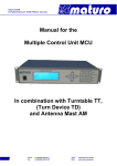
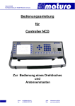
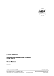
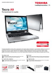
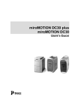
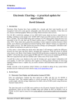
Manual
for
Controller NCD
For the operation of Turntables TT,
Turn Device TD
and Antenna Masts
Index
1) General Instructions and Precautions
Page 3
2) Technical Data of Controller NCD
Page 4
3) Commissioning
Page 6
4) Menu Guidance
Page 7
4.1)
4.2)
4.3)
4.4)
4.5)
4.6)
4.7)
4.8)
4.9)
4.10)
4.11)
4.12)
4.13)
Page 8
Page 10
Page 11
Page 12
Page 12
Page 13
Page 13
Page 14
Page 15
Page 15
Page 16
Page 16
Page 17
Switch on Positioner
Referencing
Positioning
Actual and target position
Input of a Value
Settings
Setting of Tilt function and measurement Distance
Error Diagnostics
GPIB or LAN settings
Menu
GPIB or LAN Logger
Remote Address
PLC Update
5) Trouble Shooting Controller NCD
Appendix
- Warranty Statement
- Declaration of Conformity
- Remote commands
Page 18
Page 20
Page 21
Page 22
2
1) General Instructions and Precautions
Before this device is applied with power:
Ground it properly through the protective conductor of the power cable to a power source
provided with protective earth contact. Any interruption of the protective (grounding)
conductor, inside or outside the device, or disconnection of the protective earth terminal
could result in personal injury.
The electrical installation of this product must be accomplished by an individual who is
authorized to so do by the appropriate local authority. The installation must be in compliance
with local electrical safety codes.
Only qualified personnel are allowed to operate or service this equipment.
Before making service, contact maturo GmbH
Service or modifications of the device by yourself may void your warranty.
If you attempt to service the unit by yourself, disconnect all electrical power before starting.
There are voltages at many points in the components which could, if contacted, cause
personal injury. Only trained service personnel are allowed to perform adjustments and/or
service procedures upon this device. Capacitors inside this instrument may still be charged
even when instrument is disconnected from its power source.
Stay clear of moving components during the operation of the device.
Do not operate the device while somebody is close to moving parts.
The protection of the area of risk at site is part of the operator.
Read this manual completely before starting installation. This equipment must be installed
and operated only by qualified personnel.
Regularly inspect all equipment and conduct scheduled maintenance in accordance with
the factory recommendations provided. Only use replacement parts and fasteners ordered
directly from the factory.
Information presented enclosed is subject to change as product enhancements are made regularly.
Every effort has been made to ensure that the information in this manual is accurate. However, no
liability or guarantee is assumed for the up-to-dateness, correctness and completeness of the
information provided herein.
Pictures included are for illustration purposes only and do not represent all possible configurations.
3
2) Technical Data of Controller NCD
The Multiple Control Device NCD is suited for the operation of up to 8 devices with multiple
axis of motion. Those devices can be any combinations of antenna masts, turntables, cable
guide rails or any other positioning equipment.
This controller NCD permits the operation in manual, semi-automatic and remote control
mode via IEEE 488.2 (GPIB bus), or optionally other interfaces, of multiple devices
simultaneously.
Figure: NCD with option “tip-up handle”
Technical Data
Data interfaces
IEEE 488.2 (GPIB-Bus) and Ethernet
Transmission
Fibre optic cable 1G50/125 (up to 2000 m distance)
Transfer rate
100 Mbit/s (fast Ethernet)
Display
5.7“ TFT Touch screen-Display
Voltage
Current consumption
Fuse
100-240 VAC, 47-63 Hz, single phase
70W
2x T 1.6A
max.
Size (W X D)
19” Rack mount and table unit (427 x 300 mm)
Height
3 HE (133 mm)
Temperature range
Total weight
Accessories
5°C - 40°C
approx. 8 kg
1.5 m power supply cable, Service manual
4
Brief description of NCD
The multiple control device NCD works with KeySight (former Agilent), R&S, Teseq and other
software. The IEEE 488 (GPIB) is available as a standard interface device. Other interfaces
available upon request.
Highlights:
-
User-friendly, time-saving function keys optionally available
The function keys F1 to F10 allows the implementation of individual, customerspecific sequence programs for user-friendly, times-saving handling and operation.
The individual programs can be stored and accessed by one function key.
-
Error analysis based on error codes
Diagnosis via USB interface possible
Optional analysis via internet and Ethernet interface possible
-
USB interface
Updates easily implemented by USB stick
Possibility to plug in a computer mouse and keyboard
-
Easy operation with touch panel
Fast and reliable operability based on touch panel technology
Layout of touch screen display can easily be adjusted according to customers’
request
-
Position keys
With the position keys JOG+/JOG- the Positioners can easily be moved in manual
mode.
-
Real-time capable
Each program cycle will finished in the default time frame be no matter how many
devices are controlled at the same time. Due to this feature no overflow of commands
can happen when using fast remote computers.
-
Handheld control unit
Easy implementation of standard or customer-specific handheld control units possible
-
Precise Display Accuracy
The display resolution is highly precise with position readout increments of 1 mm
respectively 0.1 degree.
Higher resolutions possible upon request.
-
Many additional options possible
Emergency stop buttons, handheld control units (HCU), luminaire, analogue outputs
and much more additional features upon request
5
3) Commissioning Controller NCD
Bus Connection
The connection between the Controller NCD and the Positioner is performed by the included
fibre optic cable.
Take care that the colours of cables match with the stickers at the backside of the controller
and the drive units.
All Positioners will be activated automatically. If an additional device is connected, there is no
need of a restart.
Power Supply
The power supply of all devices must be 110-240 VAC / 47-63Hz.
Switch On
Switch on black power switch of the Positioners.
Switch on black power switches at front and back of the controller.
Attention:
The fibre optic cables of NCD are highly sensitive, ensure that it is not
bent too much or gets damaged any otherwise!
If cables or ports are not in use, the included dust protection covers
must be used!
Even a minor, hardly visible dirtying of cable ends or feed-throughs
(FSMA) harms the connection, up to complete communication
malfunction!
Therefore please have a look at Chapter 5) Troubleshooting.
6
4) Menu Guidance
Panel
The picture below shows the control panel
Stop-Key
Start-Key
Enable-Key
Reference-Key
Menu-Key
Keyboard
USB-Ports
Power switch
F-Keys
Device selection
Switch Device 1-5 to 5-8
Switch On
The following picture appears after boot routine.
(Note: The picture above may not the original picture for your controller)
There is no need to connect your D1 Device to the first port.
Each device can be connected to any free port of NCD.
7
4.1 Switch on Positioner
- By pressing “EN“ key all Positioner will
be activated and the LED light up green
permanently.
- By pressing e.g. “D1/D5”, each single
device can be activated or deactivated.
Whereas, at deactivating the button must be
pressed for a longer period.
- To operate the devices D5 to D8, the
button “D5-D8” must be pressed first.
LED D5-D8 out: Device D1 to D4
LED D5-D8 on: Device D5 to D8
- Press the relevant button for switching to
the other Positioners.
- In general, the devices are active where
the LED light is on.
8
Note: The following brief descriptions are examples, but the controlling of most
positioners is similar. Possibly your Device doesn’t have all described functions.
By selecting a turntable the picture below appears. There is no need to reference the
turntable. The displayed value of “Actual Angle” is indicated by an absolute encoder which is
saving the last position, even after power off.
By pressing “To Settings” the adjustment possibilities for the device are shown.
By pressing key for Antenna Mast the picture below appears and the antenna mast is
activated. Masts must be referenced before positioning is enabled. By pressing “To Settings”
the adjustment possibilities for the device are shown.
Note: Yellow characters indicate the actual values.
At the bars which are indicated in white characters, input options are possible
9
4.2 Referencing
Before moving the antenna masts, they must be referenced.
Press “REF”-button after selecting a device in the user interface.
During the referencing, the LED of the “REF”-Button is blinking, after completion it lights
permanently. This process must be done with every Mast device and after every restart of
the NCD or of the device.
It is recommended to move masts to a low position before power off; otherwise the
referencing can take a long time.
If you have a TAM or BAM device, the buttons “Tilt Up” and “Tilt Down” can be used to adjust
the carriage considering to the bubble level. The angle is saved as 0⁰ by pressing “Tilt Save”
and the referencing of high starts automatically.
Other masts as AM or CAM will reference fully automatic by pressing the “REF”-button.
Referencing of TAM (or BAM)
If you have a TAM or BAM device, the buttons “Tilt Up” and “Tilt Down” can be used to adjust
the carriage considering to the bubble level.
The angle is saved as 0⁰ by pressing “Tilt Save” and the referencing of high starts
automatically.
These three buttons are also at the side of the drive box of TAM or BAM.
Other masts as AM, CAM or DAM will reference fully automatic by pressing the “REF”-button.
10
Always make sure that the TAM is in bubble level
before pressing “Save Tilt“
Serious damage can be the caused otherwise!!
4.3 Positioning
By pushing any “JOG” keys the Positioner moves in the respective direction. The movement
stops either by releasing the “JOG” key or a limit is reached.
“JOG Min” means Down for Masts and CCW for Turntables.
“JOG Max” means Up for Masts and CW for Turntables.
By entering a “JOG-Distance”, an incremental stepwise positioning is activated. The
respectively axis moves by the indicated distance pressing the “JOG” key. This stepwise
positioning can be repeated any number of times if no limit is reached.
This function can be deactivated by entering “0.0“ in the JOG- Distance menu.
The polarisation can be changed by pressing “To Hor” or “To Ver” keys.
11
4.4 Actual and Target Position
The actual position is indicated in the respectively column “Actual Angle/High”.
Any target position can be entered at “New Angle/High” and afterwards the positioning can
be activated with the “START” key.
During the movement the positioning can be stopped with the “STOP” key and activated
again with the “START” key.
Note: The “START” key is only valid for the selected device whereas the “STOP” key is valid
for all devices.
4.5 Input of a Value
The input of any numerical value can be entered by either the Touch panel or the number
pad.
By pressing „New Angle/High“-key the input is activated.
The following input field appears:
Any numerical value within the displayed minimum and maximum limits can be entered.
The value is applied by pressing “OK” key.
The input can also be done by the number pad and applied with “Enter” key.
12
4.6 Settings
Speed and Acceleration/Deceleration
The speed and acceleration for both rotation axes can be changed by pushing the “Speed” or
“Acc” keys at the Touch panel. Different speeds and accelerations can be entered within the
indicated limits.
The indicated values are always used at operation directly from the NCD. At remote control
via GPIB the values of speed and acceleration can be adjusted separately by the software.
Note: Acceleration/Deceleration cannot be set with GPIB
4.7 Settings for Tilt-Function and measurement distance at TAM
At this menu it is possible to activate or deactivate the tilt function and to set the
measurement distance and EUT height.
EUT height:
- Before referencing balance the antenna with the levels.
- After referencing or if the EUT height was changed with key “EUT High”, the new EUT
height must first be confirmed by pressing the “Start” key and moving to the new
height.
- The movement of the antenna mast is now possible again.
With these settings the required tilt angle depending on the distance is calculated
automatically.
13
4.8 Error Diagnostics
If an error occurs, the diagnostics button in main screen of the device changes to red.
To reset the error, press the diagnostics button first.
The error can be reset by pressing the button in the down left corner.
If an error appears regularly or always, you can get additional information to the error by
pressing “NC1” – “NC4” Buttons. Each single motor of the device has its own NC menu.
The screen below appears and provides more detailed information. This can be important for
maturo to give a quick solution to your problem.
If you need support, please always note the serial number of your device and the error
texts before contacting maturo.
14
4.9 GPIB or LAN settings
At this menu the speed with GPIB or LAN, the relevant limits and the device addresses are
indicated.
If no other values are chosen, the default values are selected automatically.
4.10 Menu
By pressing the “MENU” key an overview of the system settings are shown.
15
4.11 GPIB or LAN Logger
The “GPIB Logger” or “LAN Logger” menu enables the analysis and interpretation of the
received commands.
- “Init” key removes the entries in the table.
- By pressing the “Back” key, the system menu appears again.
4.12 Remote Address
Any Remote Address can be selected here.
- The current Remote Address is indicated.
- Change address by entering a new number and press “Set GPIB-Address”
16
It is possible to change to IP-address of the Controller. (Only with LAN interface)
-Enter the new IP-address and subnetmask.
-Press “Create Registry File”
-Press “Update IP Address”
-Press “Yes”
-Press “Yes”
The Controller restarts automatically with the new IP-address.
4.13 PLC-Update
It is possible to update the Software of the Controller via the USB port. maturo can provide a
boot project which needs to be copied to an USB stick.
By pressing “PLC-Update” the update will be copied and activated at the next restart of the
controller.
For a safety update the actual Software from the controller can be saved on the USB Stick
and can be restored if there are problems with the new Update.
By pressing “Save Current PLC” the Software from the controller will be copied to the USB
Stick.
By pressing “Restore Saved PLC” the saved Software from the USB Stick will be copied to
the controller.
More detailed instructions are given with every update.
17
5) Trouble Shooting Controller NCD
If there are problems with the controller, please always carry out the following first:
1. Check power supply – must be between 100V and 240V
2. Check fuses at the backside of the controller
3. Check fuse at the Positioner
4. Check fibre optic cables and connections (if possible change cables from a different
device and check)
5. Use a short cable for connection directly to the device in the chamber
6. Disconnect the power supply of the device and the controller.
Reconnect the power supply and carry out referencing
Please contact our service department by:
Phone: +49 9606 9239130
Or by
Email: [email protected]
When contacting maturo, please always provide the serial number of the products.
18
Trouble Shooting Controller NCD – cable cleaning
If you have connectivity malfunction, the cables or the feed-throughs (FSMA) may be dirty.
Even if the cables never where disconnected, some dirt can get inside over time.
The cables may even not look dirty and still the attenuation loss can be too high!
For best cleaning result, use the following
tools:
At least 90% pure cleaning alcohol
(other detergents can make it even worse!)
Compressed air spray can
(optionally)
Small cotton sticks
Microfiber cloth
Use the microfiber cloth
to clean all cable ends
Use the cotton sticks
and compressed air to
clean all feed-throughs
(FSMA)
After cleaning, reconnect
all cables and check
connectivity again.
When not using cables
or devices, always put
on the provided dust
covers!
19
Warranty Statement
Maturo GmbH, hereinafter referred as maturo, warrants that our standard products are free
from defect in materials and workmanship for a period of one year from date of shipment, if
maintenances are done regularly. Standard maturo products include the following:
-
Antenna Mast and Stands
-
Turntables and Turn Devices
-
Cable guide rails
-
Controllers
-
Dynamometers for the automotive industry
If the Buyer notifies the Seller of a defect within the warranty period, the Seller will, at the
Seller’s option, either repair and/or replace those products that prove to be defective.
There will be no charge for warranty services performed at the location maturo designates.
The customer must, however, prepay inbound shipping costs and any duties or taxes.
Maturo will pay outbound shipping cost for a carrier of maturo’s choice, exclusive of any
duties or taxes. If maturo determines that warranty service can only be performed at the
customer’s location, the customer will not be charged for maturo’s travel related costs.
This warranty does not apply for:
- Improper storage of our products outside our area of influence,
- Errors during installation, commissioning or operation,
- Wear and tear during normal operations,
- Unqualified maintenance works,
- The application of unsuitable equipment and materials,
- The results of repair works or other activities undertaken on our products, which have
not been expressly approved by us.
- Consumable items such as fuses, batteries, etc.
- Products which have been operated outside the specifications
Note: Please always contact maturo before shipping equipment to us.
20
EG Konformitätserklärung gemäß EMV-Richtlinie 2004/108/EG
Declaration of Conformity in accordance with EMC guideline 2004/108/EC
Hiermit wird erklärt, dass das Produkt:
We hereby declare that the product:
Produktbezeichnung:
Product:
Controller NCD
Seriennummer:
Serial number:
Baujahr:
Year:
NCD/xxx/xxxxxxx
2015
Hersteller:
Manufacturer:
maturo GmbH, Am Kalvarienberg 24, 92536 Pfreimd
mit den Vorschriften folgender Europäischer Richtlinien übereinstimmt:
has been manufactured according to the regulations of the following European directives:
- 2004/108/EG
- 2004/108/EC
Elektromagnetische Verträglichkeit – EMV-Richtlinie
Electromagnetic compatibility – EMC directive
- 2006/95/EG
- 2006/95/EC
Niederspannungsrichtlinie
The Low Voltage Directive
Grundlagen dafür sind folgende harmonisierte Normen:
Basis for that are the following harmonized standards:
- EN 55022:2010
Class B
- EN 61000-4-2:2009
Level 2/3
- EN 61000-4-3:2006 + A1:2008 + A2:2010
Level 2
- EN 61000-4-4:2004 + A1:2010
Level 2
- EN 61010-1:2010
Safety requirements for electrical equipment for
measurement, control and laboratory use.
Pfreimd, den 20.02.2013
Gerhard Strehl, Managing Director
Firmenstempel
Company stamp
Ort und Datum der Ausstellung
Place and date of issue
rechtsverbindliche Unterschrift
Name and signature of authorised person
21
Remote commands for the
Controller NCD
For
Antenna Mast AM and Stands AS
Turntable TT &Turn Devices TD
22
Index
Chapter 1:
Remote Commands for Antenna Masts and Stands
Page 24
Chapter 2:
Remote Commands for Turntables & Turn Devices
Page 26
Chapter 3:
Error Messages
Page 28
Chapter 4:
General programming at NCD
Page 29
-
Addressing to multiple devices
Page 29
-
Speed setting
Page 29
-
Go to new position
Page 29
-
Readout of current position
Page 30
23
Chapter 1: Remote commands for Antenna Masts and Stands
General information
-
All outputs through the Interface-Bus are five characters long, followed by Line Feed
(0AH). Missing positions are filled with blanks (20H).
All values are transferred in CM.
Negative values are not allowed.
The commands, values and units must be transferred in capital letters and separated
by blanks.
No more than 32 characters may be sent in one transmission.
The Line Feed or the EOI can be used as an end character (CR will be ignored).
Registers
The Bus interface of the control device has several registers available. By transmitting the
register name, the register is made the current register. If the device is addressed as
TALKER, it outputs the contents of the register set.
If a value has been loaded previously with LD, it is accepted into the next following register.
Input Registers
These registers can be assigned a value with the LD command. They can be readout when
the register name is received and the control unit is then addressed as TALKER.
UL
-
Upper Limit (General)
Cannot exceed the maximum height and must not be smaller than the
minimum height.
UV
-
Upper Limit for vertical polarization
Cannot exceed the “Upper Limit”.
LL
-
Lower Limit
Cannot exceed the minimum height and must not be larger than the
maximum height.
NP
-
Next Position
Set point for the GO command.
Output Registers
These registers are only for readout of information.
CP
-
Current Position
BU
-
Busy Motor status
0: Motor is off
1: Motor is on
24
The BU register indicates if the motor and thereby also the mast is currently moving.
For mechanical reasons, the motor cannot start immediately after the receipt of a start
command.
Therefore it is necessary to wait until the mast moves (BU = 1), before it is possible to
enquire with BU whether the previous command has been completed. If the mast is already
located in the desired position when a GO command is received, BU will nevertheless be set
on 1 for approx. 0.5 sec.
Commands to Load the Registers
LD nnn CM - Load the value nnn into the register following.
Commands to Control the Mast
UP
-
Moves the mast basket up until the upper limit is reached or a STOP
command (ST) is received.
DN
-
Moves the mast basket down until the lower limit is reached or a STOP
command (ST) is received.
GO
-
Moves the mast basket to the position, which is in the set point register (NP).
P?
-
Current polarization of the antenna.
0: Horizontal polarisation
1: Vertical polarisation
PV
-
Sets the antenna to vertical polarization.
PH
-
Sets the antenna to horizontal polarization.
Commands to Control the AS
P?
-
Current polarization of the antenna.
0: Horizontal polarisation
1: Vertical polarisation
PV
-
Sets the antenna to vertical polarization.
PH
-
Sets the antenna to horizontal polarization.
25
Chapter 2: Remote commands for Turntables & Turn Devices
General information
-
All outputs through the Interface-Bus are five characters long, followed by Line Feed
(0AH). Missing positions are filled with blanks (20H).
All values are transferred in DG.
The commands, values and units must be transferred in capital letters and separated
by blanks.
No more than 32 characters may be sent in one transmission.
The Line Feed or the EOI can be used as an end character (CR will be ignored).
Registers
The Bus interface of the control device has several registers available. By transmitting the
register name, the register is made the current register. If the device is addressed as
TALKER, it outputs the contents of the register set.
If a value has been loaded previously with LD, it is accepted into the next following register.
Input Registers
These registers can be assigned a value with the LD command. They can be readout when
the register name is received and the control unit is then addressed as TALKER.
WL
-
Wise Limit cannot be larger than 400°.
CL
-
Counter-clockwise Limit cannot be smaller than -200°.
NP
-
Next Position. Set point for the GO command.
SP
-
Speed, valid numbers are 1 to 8.
Output Registers
These registers are only for readout of information.
CP
-
Current Position
BU
-
Busy Motor status
0: Motor is off
1: Motor is on
26
The BU register indicates if the motor and thereby also the turntable or turn device are
currently moving.
For mechanical reasons, the motor cannot start immediately after the receipt of a start
command.
Therefore it is necessary to wait until the turntable moves (BU = 1), before it is possible to
enquire with BU whether the previous command has been completed. If the mast is already
located in the desired position when a GO command is received, BU will nevertheless be set
on 1 for approx. 0.5 sec.
Commands to Load the Registers
LD nnn DG - Load the value nnn into the register following.
Commands to Control the Turntable or Turn Device
CW
-
Moves the table clockwise until the limit is reached
or a STOP command (ST) is send.
CC
-
Moves the turntable or turn device counter-clockwise until the limit is
reached or a STOP command (ST) is send.
GO
-
Moves the turntable or turn device to the position which is in the set
point register (NP).
ST
-
Stops the movement of the turntable or turn device.
27
Chapter 3: Error Messages
E–P
Power is sent after a loss of mains power
E–S
Syntax is sent when an invalid command is received
E–V
Value is sent when a value does not lie within the valid limits
E–D
Device is sent when the device no longer reacts, meaning that the motor does
not move in spite of the control. It is also sent if the addressed device does not
exist.
28
Chapter 4: General programming at NCD
Addressing the several devices
If several devices are connected to the NCD, the controllable device needs to be addressed.
For example (One Antenna Mast and one Turntable)
"LD 0 DV"
for the Antenna Mast
"LD 1 DV"
for the Turntable.
This applies for setting a new position and for readout of the actual position of a device!
Speed setting of a device
You can set speed 1 to 8 with the SP-Register. To change the speed of the turntable, make
the following two steps:
Select the Turntable “LD 1 DV”
Write "LD 5 SP" sets the speed to five. The speed depends on the maximum speed of the
device.
For example the maximum speed of the turntable is 2.0 U/min
(2.0 ÷ 8) * 5 = 1.25 U/min is the new speed
The maximum speed of each device can be readout in the device-menu of the NCD.
Note: The polarisation speed of the antenna mast cannot be change!
Go to a new position
For setting a new position of the turntable make the following two steps:
Select the Turntable “LD 1 DV”
Write the command "LD 180.0 DG NP GO" (the turntable moves to 180 degree)
With the commands "CC" and "CW" it is possible to move the turntable to minimum and
maximum limit.
“CC” – Turntable moves to minimum limit (e.g.: -200 degree)
“CW” – Turntable moves to maximum limit (e.g.: +400 degree)
For stopping the turntable make the following two steps:
Select the turntable “LD 1 DV”
Write the command "ST"
For setting a new position of the antenna mast follow the same steps:
Except: Select the antenna mast with writing "LD 0 DV"
Write the command "LD 300.0 CM NP GO" (the antenna mast moves to 3.0 meter)
For polarization of the antenna mast write "PV" and "PH".
29
Readout the actual position of the device:
Select the device by writing "LD x DV". (x = 0 => Antenna Mast and x = 1 => Turntable)
Write "CP" (set the Pointer to the CP-Register)
Readout of six Bytes (applies to antenna mast and turntable)
For polarization readout select the antenna mast
Write "P?" and readout the position
In general all registers can be readout in the same way.
E.g.: WL and the CL Register
Device address
0
1
2
3
4
5
Device
Antenna Mast 1
Turntable 1 (TT)
Cable Guide Rail (CGR) or Field Probe Positioner (FPP)
Turn Device (TD)
(Compact) Antenna Mast 2 or Antenna Stand
Turntable 2 (TT)
30
maturo GmbH
Am Kalvarienberg 24 o 92536 Pfreimd
Web: www.maturo-gmbh.de
o
Germany
Notes
maturo GmbH
31