1
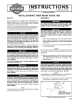
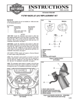
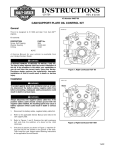
INSTRUCTIONS
®
REV.04-21-2003
-J00058
Kit Number 29982-81
22-AMP CHARGING SYSTEM
General
This kit fits all 1970 through 1988 motorcycles with Big Twin
engines.
2. Remove the original alternator and voltage regulator.
Note the positions of any spacers or shims on the
sprocket shaft during disassembly procedures.
Be sure to remove the original spacer that is positioned
inboard of the rotor (if so equipped).
See the Service Parts illustration for kit contents.
1WARNING
The rider’s safety depends upon the correct installation of
this kit. Follow the procedures listed in this instruction
sheet and in the appropriate Service Manual.
If the procedures are not within your capabilities, or if you
do not have the correct tools, have your Harley-Davidson
Dealer perform the installation. Failure to follow instructions
could result in death or serious injury.
NOTE
This instruction sheet references Service Manual information. A Service Manual for your model motorcycle is required
for this installation and is available from any HarleyDavidson Dealer.
Installation
NOTE
The alternator rotor should be removed using rotor puller
Part No. HD-95960-52B.
3. See the Service Parts illustration. Discard the original
stator mounting screws (and the mounting screw locking plate, if so equipped). Install the new stator assembly (8) using the new mounting screws (1) from the kit.
Tighten the screws to 30-40 in-lbs (3.4-4.5 Nm).
CAUTION
Do not install any combination of new style parts with
old style parts. Mixing old and new style parts will cause
permanent damage to the stator or voltage regulator.
4. See Figure 1. Place the smaller spacer washer (9) from
the kit over the sprocket shaft.
CAUTION
1WARNING
To prevent accidental vehicle start-up, which could
cause death or serious injury, disconnect negative (-)
battery cable before proceeding. (00048a)
1. Refer to the Service Manual and follow the instructions
given to remove the seat and disconnect the negative
battery cable. Retain all seat mounting hardware.
Do not strike or drop the alternator rotor. The magnets
could be loosened or damaged, which would result in
rotor failure.
5. Install the new alternator rotor assembly (8) onto the
sprocket.
6. Place the larger spacer (7) from the kit over the sprocket shaft. Place the original shim(s) (6) over the shaft.
i00031a.tif
7
2
3
4
5
6
1
9
8
Original Equipment Components
1.
Compensating sprocket nut
2.
Compensating sprocket cover assembly
3.
Sliding cam
4.
Compensating sprocket
5.
Shaft extension
6.
Shim washer(s) (various widths)
Kit Components
7.
Spacer washer (2.81 in. O.D. x 0.219 in. thick)
8.
Alternator rotor assembly
9.
Spacer washer (1.75 in. O.D. x 0.095 in. thick)
Figure 1: Alternator Rotor and Compensating Sprocket Assembly
1 of 2
7. Check the sprocket alignment.
8. Apply Loctite® 262 (red) to the threads of the compensating sprocket nut (1).
9. Install the nut and tighten to 80-100 ft-lbs (109-136 Nm).
10. Measure the length of the original voltage regulator output lead, and cut the output lead on the replacement
regulator to the same length.
NOTE
The voltage regulator output lead should be connected to
the same location as it was originally.
If the output lead will be connected to the battery positive
terminal, install the larger ring terminal (3) from the kit.
If the output lead will be connected to the silver (LOAD
SIDE) terminal of the main circuit breaker, install the smaller
ring terminal (2).
11. Strip 1/4 in. (6.4 mm) of insulation off the end of the output lead and install the appropriate ring terminal.
12. Install the voltage regulator following Service Manual
procedures.
®
Service Parts
13. Depending on the connection location of the original
voltage regulator output lead, connect the ring terminal
of the replacement regulator to either the battery positive terminal or the silver (LOAD SIDE) terminal of the
main circuit breaker.
14. Secure the regulator wiring using the cable straps (4)
from the kit.
15. Refer to the Service Manual and follow the instructions
given to re-attach the negative battery cable
16. Test the vehicle to be sure the charging system is functioning properly.
17. Remove the front crankcase stud and install the wireform
plug retainer (9). Tighten the stud to 15-17 ft-lbs (20-23
Nm).
18. Install the seat.
1WARNING
After installing seat, pull upward on front of seat to be
sure it is in locked position. While riding, a loose seat
can shift causing loss of control, which could result in
death or serious injury. (00070a)
Part No. 29982-81
Date 04/03
22-Amp Charging System
i00031a.eps
8
4
5
7
6
10
3
1
9
2
Item
1
2
3
4
5
6
Description (Quantity)
Screw, stator mounting (4)
Ring terminal #10 hole
Ring terminal 1/4 in. dia. ID
Cable strap (6)
Alternator rotor assembly
Spacer washer,
2.81 in. O.D., 0.219 in. thick
-J00058
Part No.
2712
9862
9863
10006
29963-99
Item Description (Quantity)
7
Spacer washer,
1.75 in. O.D., 0.095 in. thick
8
Stator assembly
9
Wireform plug retainer
10
Voltage regulator assembly
Part No.
29961-85
29965-81B
45095-85
74515-86
29960-85
2 of 2