1
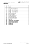
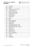
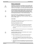
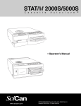
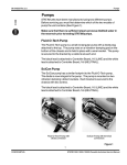
96-103920 Rev. 4.0
Steam Generator
Steam Generator
There are two types of steam generator you may encounter while
servicing a STATIM 5000 / 5000S unit, one is aluminum and the other is
stainless steel. The aluminum steam generator also has two versions,
one with a set of four stand-offs on the bottom for positioning the
thermal fuse and the other with two sets of four stand-offs on the
bottom. See Steam Generator Thermal Fuse.
Removing the Aluminum Steam Generator
CAUTION: The steam generator may be hot if the unit has been
operating. Guard against burns.
To remove the steam generator, follow these steps (see Figure 1):
1.
Turn the power switch OFF, and unplug the unit.
2.
Disconnect the steam generator thermocouple wires (1) from
Controller Board (2) terminal positions BOILER +Y and -R and
disconnect the flag terminal (3) from the position marked BOILER
directly above the terminals. Leave the screws with contact
washers in the terminals.
3.
Disconnect the black thermal fuse (4) wire from Controller
Board connector terminal block J1-3. See Steam Generator
Thermal Fuse.
4.
Trace the path of the black wire back to the base of the steam
generator (5). Carefully cut all cable ties holding the black wire.
5.
Carefully cut the cable ties (6) securing the steam generator
thermocouple lead (8) and other wires to the armature (11).
6.
Disconnect the white wire (12) attached to the terminal on the lower
half of the steam generator.
7.
Carefully cut the cable tie (13) holding the compressor tube (14)
onto the check valve inlet (15) and pull the tube off the valve.
8.
Using a 3/8-inch wrench, disconnect the compression nut (16)
holding the Teflon™ tube (17) from the top of the steam generator.
9.
Using a 7/16-inch wrench, disconnect the compression nut (18)
holding the steam generator outlet tube (19) to the steam generator
outlet fitting (20).
1
CONFIDENTIAL
STATIM L / 5000 / 5000S Cassette Autoclave Service Manual
Steam Generator
96-103920 Rev. 4.0
Steam Generator
10. Disconnect the compression nut (21) holding the steam generator
outlet tube to the probe bracket inlet fitting (22).
11. Remove the two screws (23) holding the steam generator bracket
assembly (24) to the chassis and remove the steam generator.
See Steam Generator Thermal Fuse.
1
11
Figure 1
6
3
2
9
10
22
21
19
25
18
20
8
16
17
5
1.
2.
3.
4.
5.
6.
7.
8.
12
23
steam generator
thermocouple wires
Controller Board
flag terminal
black thermal fuse wire
aluminum steam generator
cable ties
chamber thermocouple lead
steam generator
thermocouple lead
24
9.
10.
11.
12.
13.
14.
15.
16.
17.
15
4
13
14
microswitch leads
reservoir sensor leads
armature
white wire
high temperature rated cable tie
compressor tube
check valve inlet
compression nut
Teflon™ tube
7
18.
19.
20.
21.
22.
23.
24.
compression nut
steam generator outlet tube
steam generator outlet fitting
compression nut
probe bracket inlet fitting
screws
steam generator bracket
assembly
25. transducer leads (if present)
2
STATIM L / 5000 / 5000S Cassette Autoclave Service Manual
CONFIDENTIAL
96-103920 Rev. 4.0
Steam Generator
Steam Generator
Replacing the Aluminum Steam Generator
To replace the steam generator, follow these steps (see Figure 1):
1.
Make sure the power switch is OFF, and the unit is unplugged.
2.
Carefully install the steam generator bracket assembly (24) to the
chassis using two screws (23). Start the screws into the tapped
holes but do not tighten the screws.
Be careful not to bend the thermocouple leads too sharply
(min. bend radius - 3/16-inch / 5 mm). Retain the protective sleeve
on the controller board end of the thermocouple leads as long
as possible. Do not crush or pinch the thermal fuse lead.
3.
Connect the compression nut (18) holding the steam
generator outlet tube (19) to the top of the steam generator outlet
fitting (20) and the compression nut (21) holding the steam
generator outlet tube to the probe bracket inlet fitting (22).
Thread the nuts finger tight, then tighten using a 7/16-inch
wrench. Do not overtighten.
4.
Tighten the two screws holding the steam generator bracket
assembly to the chassis.
5.
Connect the compression nut (16) holding the Teflon™ tube (17)
to the top of the steam generator. Thread the nut finger tight, then
tighten using a 3/8 inch wrench. Do not overtighten.
6.
Reconnect the white wire (12) to the terminal on the lower half of
the steam generator using the retained screw with lockwasher. If
the terminal appears blackened, clean it using fine grit sandpaper.
If the terminal threads strip, use a nut on the other side of the
terminal to hold the screw.
7.
Route the black thermal fuse wire (4) from the fuse assembly along
the back of the chassis with the other wires, and connect it to
Controller Board (2) terminal J1-3.
8.
Carefully bend and route the new steam generator thermocouple
lead (8) alongside the chamber thermocouple lead to the Controller
Board. The leads must not touch the cover when the cover is
assembled to the chassis.
3
CONFIDENTIAL
STATIM L / 5000 / 5000S Cassette Autoclave Service Manual
Steam Generator
96-103920 Rev. 4.0
Steam Generator
9.
Carefully remove the protective sleeve from the end of the uninsulated steam generator thermocouple leads. Pre-bend both
leads to achieve the required shape. Reconnect the flag terminal to
the threaded lug marked BOILER on the Controller Board.
EXERCISE CAUTION: The thermocouple leads at the board end
are very fragile
One lead is colour coded: the unmarked lead is positive, +Y. The
red lead is negative, -R. Connect the unmarked lead to the terminal
marked +Y on the Controller Board. Connect the red lead to the
terminal marked -R on the Controller Board. Make sure there is
extra lead length so that the wires do not break as the screw is
tightened. Ensure that the wires are seated securely behind the
respective washers (see Figure 1 detail).
The two leads must not touch one another or any other
component. Do not calibrate a thermocouple until it is
properly installed and positioned in the unit.
10. Bundle the chamber thermocouple lead (7), the new steam
generator thermocouple lead, microswitch leads (9), transducer
leads (25) and reservoir sensor leads (10) together using nylon
cable ties (6), approximately every 2-3 inches. Secure the wires to
the top of the armature using the cable anchors provided.
11. Carefully push the compressor tube (14) onto the check valve inlet
(15) and secure the tube to the valve using a high temperature
rated cable tie (13).
12. Calibrate the steam generator thermocouple (for non S units only).
See, Thermocouple Calibration.
13. A dielectric strength test (Hi-Pot) and a protective bonding
impedance test (ground continuity) MUST be performed on the
STATIM unit. See, Required Information, Tools and Routine
Maintenance, Safety Compliance.
14. Run a sterilization cycle and observe all fittings and tubes for leaks.
Check LCD read-outs for messages indicating cycle status.
15. Reinstall the cover. See STATIM Cover Removal and
Replacement.
4
STATIM L / 5000 / 5000S Cassette Autoclave Service Manual
CONFIDENTIAL
96-103920 Rev. 4.0
Steam Generator
Steam Generator
Inspecting and Replacing the Steam Generator
Check Valve
CAUTION: The steam generator and check valve may be hot. Guard
against burns.
The steam generator check valve is found on STATIM / STATIM 5000
units.
To inspect the check valve, turn ON the compressor using the Control
Box, and allow the unit to run for a few minutes. See Required
Information and Tools, the Control Box. Allow the unit to cool to the
touch. Remove and inspect the air filter, the bacteria retentive filter (if
present) and the compressor. See Compressor Removal and
Installation. If there is evidence of water in the bacteria retentive filter,
replace the steam generator check valve and the filter. If there is
evidence of water in the compressor or if the compressor filter is wet,
replace the steam generator check valve, compressor and filters. See
Required Information, Tools and Routine Maintenance, Air Filters and
Compressor, Replacing the Compressor.
To Replace the Steam Generator Check Valve (See Figure 2):
1.
Turn the power switch OFF, and unplug the unit.
2.
Carefully cut the cable tie (1) holding the compressor tube (2) onto
the check valve (3) inlet and pull the tube off the valve.
3.
Using a 9/16-inch wrench remove the check valve. Apply the
wrench to the part of the valve closest to the steam generator (6).
Use a 7/16-inch wrench to hold the right angle brass fitting so that it
does not move. Clean any Teflon™ pipe fitting tape from the
threads in the right angle valve fitting.
4.
Prepare the right angle (4) fitting by wrapping the threads with
Teflon™ pipe fitting tape (minimum one complete wrap).
5.
Thread the new valve onto the right angle valve fitting in the top of
the steam generator (6). Using a 9/16-inch wrench on the end of
the valve closest to the fitting, tighten the valve SNUG. Do not
overtighten the new valve. Use a 7/16-inch wrench to hold the
right angle brass fitting so it does not move.
5
CONFIDENTIAL
STATIM L / 5000 / 5000S Cassette Autoclave Service Manual
Steam Generator
96-103920 Rev. 4.0
Steam Generator
1.
2.
3.
4.
5.
6.
6.
Carefully push the compressor tube (2) onto the check valve (3)
and secure the tube to the valve using a high temperature
application cable tie (1).
7.
Install replacement filters as required.
8.
Reinstall the cover. See Cover Removal and Replacement.
high temperature rated cable tie
compressor tube
check valve
right angle brass fitting
Teflon™ tube
aluminum steam generator
Figure 2
4
6
5
3
1
2
Removing the Stainless Steel Steam Generator
Assembly (see Figure 3)
1.
Turn the power switch OFF and unplug the unit.
2.
Remove cover. See Removing Cover.
3.
Using a 7/16 wrench on the compression nut connected to the
steam generator outlet tube and a 3/8 wrench on the T-fitting,
disconnect steam generator outlet tube. When the nut is
unscrewed completely, pull the tube apart gently to disengage it
from the fitting.
4.
Disconnect the water pump tube (Teflon™ tubing) by loosening the
nut at the top.
5.
Disconnect the compressor tube (Silicone tube) by pulling off
its fitting.
6
STATIM L / 5000 / 5000S Cassette Autoclave Service Manual
CONFIDENTIAL
96-103920 Rev. 4.0
Steam Generator
Steam Generator
6.
Disconnect the electrical connections at the PC board. Look for the
connections on the left side of the board marked “BL”. Disconnect
wire N and wire L of the “BL” set.
7.
Loosen the mounting screws holding the compressor bracket to the
chassis and gently lift the compressor to trace the path of the black
and white wire to the steam generator and cut all the cable ties
holding the black wire and the white wire.
8.
Disconnect steam generator thermocouple at the PC board.
The connection on the board is located behind the pressure
transducer board, which is held into place by a blue bracket.
8.1 To disconnect the steam generator thermocouple you must
remove the pressure transducer board.
8.2 Do this by unclasping the latches on either side of the blue
bracket and removing the board.
8.3 Disconnect the wires marked BOILER and trace the wire back to
the steam generator, carefully cutting the cable ties to free
the wire.
9.
Loosen the mounting screws that hold the bracket adapter to the
chassis and remove the steam generator with the adapter together.
Replacing the Stainless Steel Steam Generator Assembly
1.
Bring the steam generator into position aligning the bracket
adapter’s mounting holes with the mounting holes in the chassis
using screws, but do not tighten.
2.
Reconnect the steam generator outlet tube by pushing it together
as far as it will go and finger tighten.
3.
Tighten the mounting screws holding the steam generator with the
bracket adapter to the chassis.
4.
Tighten the compression fitting nut into place – make sure to use
two wrenches, one on the T–fitting and the other on the nut.
5
Reconnect the water pump by tightening the nut with the Teflon™
tubing all the way into position.
7
CONFIDENTIAL
STATIM L / 5000 / 5000S Cassette Autoclave Service Manual
Steam Generator
96-103920 Rev. 4.0
Steam Generator
6.
Reconnect the compressor (Silicone) tube to its fitting and tighten
with a high temperature rated cable tie.
7.
Route the black and the white thermal fuse wires and connect
these on the left side of the PC board in the BL set; the black wire
to the connection marked L and the white wire to the connection
marked N.
8.
Bundle the loose wires together using nylon cable ties every
2-3 inches.
9.
Tighten the mounting screws to secure the compressor bracket to
the chassis.
10. Reconnect the steam generator thermocouple to the PC board.
11. Put the pressure transducer board back into place in its bracket.
12. Bundle the chamber thermocouple lead, the new steam generator
thermocouple lead, microswitch leads, transducer leads, and
reservoir sensor leads together using nylon cable ties,
approximately every 2-3 inches. Secure the wires to the top of the
armature using the cable anchors provided.
13. A dielectric strength test (Hi-pot) and a protective bonding
impedance test (ground continuity). Must be performed on the
STATIM unit. See Required Information, Tools and Routine
Maintenance.
14. Run a sterilization cycle and observe all fittings and tubes for leaks.
Check LCD read outs for messages indicating cycle status.
15. Reinstall the cover. See Cover Removal and Replacement.
NOTE: Calibration of stainless steel steam generator thermocouple on
S-class units is NOT required.
8
STATIM L / 5000 / 5000S Cassette Autoclave Service Manual
CONFIDENTIAL
96-103920 Rev. 4.0
Steam Generator
Steam Generator
1.
2.
3.
4.
5.
6.
7.
8.
Compression nut
Steam generator outlet tube
T–fitting
Teflon™ tube
Compressor tube
Compressor bracket
Steam generator
thermocouple lead
Bracket adaptor
2
1
3
Figure 3
4
5
8
7
6
9
CONFIDENTIAL
STATIM L / 5000 / 5000S Cassette Autoclave Service Manual
Steam Generator
96-103920 Rev. 4.0
Document Change Record
Document 96-103920
Title: Steam Generator
Revision
ECO
Notes
Date
4.0
04-0020
Updated chapter as per prEN13060 requirements.
January 16, 2004
3.0
99-0059
Added 5000S
April 14, 1999
2.0
98-0290
Photos replace line. Text changed to include addition of
transducer if present.
December 2, 1997
1.0
96-088
Initial Release
May 29, 1996
10
STATIM L / 5000 / 5000S Cassette Autoclave Service Manual
CONFIDENTIAL