1
Manual Part No.
C4077-90960
Printed on at least
50% Total Recycled Fiber with
at least 10% Post-Consumer Paper
*C4077-90960*
*C4077-90960*
C4077-90960
HP LaserJet 5Si Family Printers Service Manual
Copyright© 1997
Hewlett-Packard Co.
Printed in USA 7/97
English
HP LaserJet 5Si Family
Printers Service Manual
Service Manual
HP LaserJet 5Si (C3166A)
HP LaserJet 5Si MX (C3167A)
HP LaserJet 5Si NX (C3950A)
HP LaserJet 5Si HM (C3124A)
HP LaserJet 5Si Mopier
(C4076A/C4077A/C4176A)
Conventions
This manual uses the following conventions:
The names of major printer parts and assemblies are Capitalized.
Color is used to emphasize items which are important to the material under
discussion.
Bold is used for emphasis, particularly in situations where italic type would
be confusing.
Italic type is used to indicate related documents or emphasis.
Note
Notes contain important information set off from the text.
Caution
Caution messages alert you to the possibility of damage to equipment or
loss of data.
WARNING!
Warning messages alert you to the possibility of personal injury.
i
Chapter Descriptions
1 Product Information
Contains printer features and product overview, tray capacities and
sizes, media specifications, service approach, and how to get technical
assistance.
2 Site Requirements
Contains space and environmental requirements.
3 Operating Overview
Contains details about control panel menus, restoring factory defaults, and
resetting and testing the printer.
4 Maintenance and Adjustments
Contains cleaning and preventive maintenance information, and
adjustment procedures for Tray 2, Tray 3, and Tray 4.
5 Functional Overview
Contains block diagrams and basic theory of operation for the printer
systems, paper paths, and paper handling accessories.
6 Removal and Replacement
Contains step-by-step procedures for replacing field replaceable units
(FRUs) in the printer, 2000-Sheet Input Unit, Multi-Bin Mailbox, and
the Mailbox with Stapler.
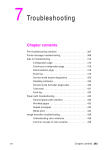
7 Troubleshooting
Contains a preliminary troubleshooting table, a table with descriptions and
recommended actions for all control panel messages, image defect samples,
and troubleshooting checks and tools.
8 Parts and Diagrams
Contains exploded view drawings and part number listings for all
replaceable parts in the printer, 2000-Sheet Input Unit, Multi-Bin Mailbox,
and Mailbox with Stapler.
A Parts Index
Contains two replaceable parts tables: one sorted alphabetically by part
name, and one sorted numerically by part number. Both tables are cross
referenced to the diagrams in Chapter 8.
ii
B I\O Information
Contains basic cabling and configuration information for connecting the
printer to supported networks.
C Regulatory Information
Contains required safety and compliance statements.
Subject Index
Contains an alphabetical, cross referenced listing of information found in
the main body of the manual.
iii
List of Figures
Figure 1-1
Figure 1-2
Figure 1-3
Figure 1-4
Figure 1-5
Figure 1-6
Figure 2-1
Figure 3-1
Figure 3-2
Figure 3-3
Figure 4-1
Figure 4-2
Figure 4-3
Figure 5-1
Figure 5-2
Figure 5-3
Figure 5-4
Figure 5-5
Figure 5-6
Figure 5-7
Figure 5-8
Figure 5-9
Figure 5-10
Figure 5-11
Figure 5-12
Figure 5-13
Figure 5-14
Figure 5-15
Figure 5-16
Figure 5-17
Figure 5-18
Figure 5-19
Figure 5-20
Figure 5-21
Figure 5-22
Figure 5-23
Figure 6-1
Figure 6-2
iv
Sample Model and Serial Number Labels . . . . . . . . .
HP LaserJet 5Si/5Si MX/NX and Mopier Engine - Front
and Right Side View with Tray 1 Open . . . . . . . . . .
HP LaserJet 5Si Mopier - Front and Right Side View
with Tray 1 Open . . . . . . . . . . . . . . . . . . . . .
Rear and Left Side View . . . . . . . . . . . . . . . . . .
HP LaserJet 5Si/5Si MX/NX Optional Paper
Handling Accessories . . . . . . . . . . . . . . . . . . . .
Sample 5% Page Coverage . . . . . . . . . . . . . . . . .
Printer Space Requirements . . . . . . . . . . . . . . . .
Control Panel Layout . . . . . . . . . . . . . . . . . . .
PCL Configuration Page . . . . . . . . . . . . . . . . . .
PCL Menu Map Page . . . . . . . . . . . . . . . . . . . .
Image Area Margins . . . . . . . . . . . . . . . . . . . .
Tray 2/3 Position Adjustment . . . . . . . . . . . . . . .
Tray 4 Position Adjustment . . . . . . . . . . . . . . . .
Printer Functional Block Diagram . . . . . . . . . . . .
Low Voltage Power Distribution System . . . . . . . . .
Low Voltage Power Supply . . . . . . . . . . . . . . . .
High Voltage Power Supply contacts . . . . . . . . . . .
Normal Mode vs EconoMode . . . . . . . . . . . . . . . .
Image Formation Block Diagram . . . . . . . . . . . . .
Photosensitive Drum . . . . . . . . . . . . . . . . . . . .
Drum Cleaning . . . . . . . . . . . . . . . . . . . . . . .
Primary Charging Roller . . . . . . . . . . . . . . . . . .
Image Writing . . . . . . . . . . . . . . . . . . . . . . .
Image Development . . . . . . . . . . . . . . . . . . . .
Image Transferring and Media Separation . . . . . . . .
Image Fusing . . . . . . . . . . . . . . . . . . . . . . . .
Printer Paper Paths . . . . . . . . . . . . . . . . . . . .
Printer Sensors, Solenoids, Clutches, Motors, and Fans .
2000-Sheet Input Unit Paper Path . . . . . . . . . . . .
2000-Sheet Input Unit Sensors, Switches, Clutches,
and Motors . . . . . . . . . . . . . . . . . . . . . . . . .
Multi-Bin Mailbox Paper Paths . . . . . . . . . . . . . .
Multi-Bin Mailbox/Mialbox With Stapler Sensors
and Motors . . . . . . . . . . . . . . . . . . . . . . . . .
Stapling Unit Paper Paths . . . . . . . . . . . . . . . . .
Stapler Sensors and Motors . . . . . . . . . . . . . . . .
General Timing Diagram (1 of 2) for LJ 5Si/5Si MX . . .
General Timing Diagram (2 of 2) for LJ 5Si/5Si MX . . .
Phillips vs. Posidriv Screwdrivers . . . . . . . . . . . . .
Control Panel . . . . . . . . . . . . . . . . . . . . . . . .
.
1-7
. 1-14
. 1-15
. 1-16
.
.
.
.
.
.
.
.
.
.
.
.
.
.
.
.
.
.
.
.
.
.
.
.
.
1-17
1-22
2-4
3-3
3-26
3-28
4-7
4-8
4-9
5-4
5-5
5-6
5-7
5-9
5-12
5-13
5-14
5-15
5-16
5-17
5-18
5-19
5-20
5-22
5-23
. 5-25
. 5-28
.
.
.
.
.
.
.
5-30
5-33
5-35
5-41
5-42
6-6
6-17
Figure 6-3
Figure 6-4
Figure 6-5
Figure 6-6
Figure 6-7
Figure 6-8
Figure 6-9
Figure 6-10
Figure 6-11
Figure 6-12
Figure 6-13
Figure 6-14
Figure 6-15
Figure 6-16
Figure 6-17
Figure 6-18
Figure 6-19
Figure 6-20
Figure 6-21
Figure 6-22
Figure 6-23
Figure 6-24
Figure 6-25
Figure 6-26
Figure 6-27
Figure 6-28
Figure 6-29
Figure 6-30
Figure 6-31
Figure 6-32
Figure 6-33
Figure 6-34
Figure 6-35
Figure 6-36
Figure 6-37
Figure 6-38
Figure 6-39
Figure 6-40
Figure 6-41
Figure 6-42
Figure 6-43
Figure 6-44
Figure 6-45
Figure 6-46
Figure 6-47
Figure 6-48
Figure 6-49
Figure 6-50
AC Access Cover . . . . . . . . . . . . . . . . . . .
Back Cover . . . . . . . . . . . . . . . . . . . . . .
Front Cover (1 of 2) . . . . . . . . . . . . . . . . . .
Front Cover (2 of 2) . . . . . . . . . . . . . . . . . .
Left Lower Cover . . . . . . . . . . . . . . . . . . .
Top Cover (1 of 2) . . . . . . . . . . . . . . . . . . .
Top Cover (2 of 2) . . . . . . . . . . . . . . . . . . .
Delivery Unit (1 of 2) . . . . . . . . . . . . . . . . .
Delivery Unit (2 of 2) . . . . . . . . . . . . . . . . .
Diverter Assembly . . . . . . . . . . . . . . . . . .
Diverter Door Assembly . . . . . . . . . . . . . . .
Right Lower Door Assembly (1 of 3) . . . . . . . . .
Right Lower Door Assembly (2 of 3) . . . . . . . . .
Right Lower Door Assembly (3 of 3) . . . . . . . . .
Fan 1, Laser/Scanner (1 of 2) . . . . . . . . . . . . .
Fan 1, Laser/Scanner (2 of 2) . . . . . . . . . . . . .
Fan 2, LVPS . . . . . . . . . . . . . . . . . . . . . .
Fan 3, Formatter . . . . . . . . . . . . . . . . . . .
Fan 4, Delivery Unit . . . . . . . . . . . . . . . . .
Feeder Assembly (1 of 2) . . . . . . . . . . . . . . .
Feeder Assembly (2 of 2) . . . . . . . . . . . . . . .
Formatter Assembly . . . . . . . . . . . . . . . . .
Fusing Assembly . . . . . . . . . . . . . . . . . . .
Laser/Scanner Assembly . . . . . . . . . . . . . . .
Main Gear Assembly (1 of 3) . . . . . . . . . . . . .
Main Gear Assembly (2 of 3) . . . . . . . . . . . . .
Main Gear Assembly (3 of 3) . . . . . . . . . . . . .
Main Motor . . . . . . . . . . . . . . . . . . . . . .
Paper Input Unit . . . . . . . . . . . . . . . . . . .
DC Controller PCA . . . . . . . . . . . . . . . . . .
Output Paper Sensor PCA (1 of 4) . . . . . . . . . .
Output Paper Sensor PCA (2 of 4) . . . . . . . . . .
Output Paper Sensor PCA (3 of 4) . . . . . . . . . .
Output Paper Sensor PCA (4 of 4) . . . . . . . . . .
Paper Size PCA (1 of 3) . . . . . . . . . . . . . . . .
Paper Size PCA (2 of 3) . . . . . . . . . . . . . . . .
Paper Size PCA (3 of 3) . . . . . . . . . . . . . . . .
High Voltage Power Supply . . . . . . . . . . . . .
Low Voltage Power Supply . . . . . . . . . . . . . .
Registration Assembly (1 of 3) . . . . . . . . . . . .
Registration Assembly (2 of 3) . . . . . . . . . . . .
Registration Assembly (3 of 3) . . . . . . . . . . . .
Tray 1 Feed Roller . . . . . . . . . . . . . . . . . .
Tray 1 Separation Pad . . . . . . . . . . . . . . . .
Tray 2 and 3, Pickup, Feed, and Separation Rollers
Paper Input Unit Sensor (PS2) . . . . . . . . . . . .
Registration Sensor (PS1) . . . . . . . . . . . . . .
Face-Up Solenoid Assembly, SL3 . . . . . . . . . .
.
.
.
.
.
.
.
.
.
.
.
.
.
.
.
.
.
.
.
.
.
.
.
.
.
.
.
.
.
.
.
.
.
.
.
.
.
.
.
.
.
.
.
.
.
.
.
.
.
.
.
.
.
.
.
.
.
.
.
.
.
.
.
.
.
.
.
.
.
.
.
.
.
.
.
.
.
.
.
.
.
.
.
.
.
.
.
.
.
.
.
.
.
.
.
.
.
.
.
.
.
.
.
.
.
.
.
.
.
.
.
.
.
.
.
.
.
.
.
.
.
.
.
.
.
.
.
.
.
.
.
.
.
.
.
.
.
.
.
.
.
.
.
.
. 6-18
. 6-19
. 6-21
. 6-21
. 6-22
. 6-24
. 6-24
. 6-26
. 6-26
. 6-27
. 6-28
. 6-29
. 6-30
. 6-30
. 6-31
. 6-32
. 6-33
. 6-34
. 6-35
. 6-37
. 6-37
. 6-38
. 6-40
. 6-41
. 6-43
. 6-43
. 6-44
. 6-45
. 6-46
. 6-47
. 6-49
. 6-49
. 6-50
. 6-50
. 6-51
. 6-52
. 6-52
. 6-53
. 6-54
. 6-56
. 6-56
. 6-57
. 6-58
. 6-59
. 6-60
. 6-61
. 6-62
. 6-63
v
Figure 6-51
Figure 6-52
Figure 6-53
Figure 6-54
Figure 6-55
Figure 6-56
Figure 6-57
Figure 6-58
Figure 6-59
Figure 6-60
Figure 6-61
Figure 6-62
Figure 6-63
Figure 6-64
Figure 6-65
Figure 6-66
Figure 6-67
Figure 6-68
Figure 6-69
Figure 6-70
Figure 6-71
Figure 6-72
Figure 6-73
Figure 6-74
Figure 6-75
Figure 6-76
Figure 6-77
Figure 6-78
Figure 6-79
Figure 6-80
Figure 6-81
Figure 6-82
Figure 6-83
Figure 6-84
Figure 6-85
Figure 6-86
Figure 6-87
Figure 6-88
Figure 6-89
Figure 6-90
Figure 6-91
Figure 6-92
Figure 6-93
Figure 6-94
Figure 6-95
Figure 6-96
Figure 6-97
Figure 6-98
vi
Transfer Roller Assembly . . . . . . . . . . . . .
Tray 1 Assembly . . . . . . . . . . . . . . . . . .
Tray 4, Back Cover . . . . . . . . . . . . . . . . .
Tray 4, Left Cover . . . . . . . . . . . . . . . . .
Tray 4, Right Cover . . . . . . . . . . . . . . . .
Tray 4, Main Drive Assembly . . . . . . . . . . .
Tray 4, Paper Tray . . . . . . . . . . . . . . . . .
Tray 4, PCA Controller . . . . . . . . . . . . . . .
Tray 4, Pickup Assembly . . . . . . . . . . . . . .
Tray 4, Pickup Assembly Photosensors . . . . . .
Tray 4, Power Supply . . . . . . . . . . . . . . .
Tray 4 Rollers: Pickup, Feed, and Separation . .
Tray 4, Switch Assemblies . . . . . . . . . . . . .
Tray 4, Transfer Assembly . . . . . . . . . . . . .
Multi-Bin MailBox/Mailbox with Stapler Covers .
MBM/MwS, Delivery Head Ribbon Cable . . . . .
MBM/MwS, Delivery Head, Mounting Screws . .
MBM/MwS, Delivery Head, Pulley Detail . . . .
MBM/MwS, Flipper Assembly Connector . . . . .
MBM/MwS, Flipper Assembly Mounting Screws .
MBM/MwS, Flipper Assembly Ground Wire . . .
MBM/MwS, Input Paper Guide . . . . . . . . . .
MBM/MwS, Interlock Switch . . . . . . . . . . .
MBM/MwS, Jam Access Door Springs . . . . . .
MBM/MwS, Jam Access Door E-Clip . . . . . . .
MBM/MwS, Jam Access Door String Connection .
MBM/MwS, Elevator Pulley Tension Spring . . .
MBM/MwS, Pulley Housing Release . . . . . . .
MBM/MwS, Metallic Tape Retaining Pin . . . . .
MBM/MwS, Metallic Tape Release . . . . . . . .
MBM/MwS, Metallic Tape Housing . . . . . . . .
MBM/MwS, Delivery Head Motor . . . . . . . . .
MBM/MwS, Transport Belt Motor Screws . . . .
MBM/MwS, Transport Belt Drive Gear . . . . . .
MBM/MwS, Transport Belt Encoder . . . . . . .
MBM/MwS, Bin Removal . . . . . . . . . . . . .
MBM/MwS, PCA Removal . . . . . . . . . . . . .
MBM/MwS, Anti-Curl String Lower Connection .
MBM/MwS, Anti-Curl String Upper Connection .
MBM/MwS, Anti-Curl String Middle Connection
Mailbox with Stapler, Stapler Removal . . . . . .
Mailbox with Stapler, Stapler Removal . . . . . .
Mailbox with Stapler, Stapler Removal . . . . . .
Mailbox with Stapler, Stapler Removal . . . . . .
Mailbox with Stapler, Stapler Removal . . . . . .
Mailbox with Stapler, Stapler Removal . . . . . .
Mailbox with Stapler, Stapler Removal . . . . . .
Mailbox with Stapler, Stapler Removal . . . . . .
.
.
.
.
.
.
.
.
.
.
.
.
.
.
.
.
.
.
.
.
.
.
.
.
.
.
.
.
.
.
.
.
.
.
.
.
.
.
.
.
.
.
.
.
.
.
.
.
.
.
.
.
.
.
.
.
.
.
.
.
.
.
.
.
.
.
.
.
.
.
.
.
.
.
.
.
.
.
.
.
.
.
.
.
.
.
.
.
.
.
.
.
.
.
.
.
.
.
.
.
.
.
.
.
.
.
.
.
.
.
.
.
.
.
.
.
.
.
.
.
.
.
.
.
.
.
.
.
.
.
.
.
.
.
.
.
.
.
.
.
.
.
.
.
.
.
.
.
.
.
.
.
.
.
.
.
.
.
.
.
.
.
.
.
.
.
.
.
.
.
.
.
.
.
.
.
.
.
.
.
.
.
.
.
.
.
.
.
.
.
.
.
. 6-64
. 6-65
. 6-67
. 6-68
. 6-69
. 6-70
. 6-71
. 6-72
. 6-73
. 6-74
. 6-75
. 6-76
. 6-77
. 6-79
. 6-80
. 6-81
. 6-82
. 6-82
. 6-83
. 6-84
. 6-84
. 6-85
. 6-86
. 6-88
. 6-88
. 6-89
. 6-91
. 6-91
. 6-93
. 6-93
. 6-94
. 6-95
. 6-96
. 6-97
. 6-97
. 6-98
. 6-99
6-100
6-101
6-101
6-102
6-103
6-104
6-105
6-106
6-106
6-107
6-108
Figure 6-99 Mailbox with Stapler, Stapler Removal . . . . . . . . . .
Figure 7-1 HP LaserJet 5Si / 5Si MX / 5Si Mopier
Troubleshooting Process . . . . . . . . . . . . . . . . . .
Figure 7-2 HP LaserJet 5Si / 5Si MX / 5Si Mopier
Troubleshooting Process . . . . . . . . . . . . . . . . . .
Figure 7-3 Fan Location and Airflow . . . . . . . . . . . . . . . . .
Figure 7-4 Engine Test Button . . . . . . . . . . . . . . . . . . . . .
Figure 7-5 Configuration Page Example . . . . . . . . . . . . . . . .
Figure 7-6 Menu Page Example . . . . . . . . . . . . . . . . . . . .
Figure 7-7 Communications Link (C-Link) Cables, Supported
Daisy Chain Connections . . . . . . . . . . . . . . . . . .
Figure 7-8 Error Log Page . . . . . . . . . . . . . . . . . . . . . . .
Figure 7-9 MIO Block on Configuration Page . . . . . . . . . . . . .
Figure 7-10 Paper Path Test Source and Output Selection . . . . . .
Figure 7-11 Clearing Staple Jams . . . . . . . . . . . . . . . . . . . .
Figure 7-12 Scanbar and MBM Interlock Switch (SW1) . . . . . . . .
Figure 7-13 High-Voltage Power Supply Contacts . . . . . . . . . . .
Figure 7-14 Tray 2 and Tray 3 (2) Paper Out Flags . . . . . . . . . .
Figure 7-15 Vertical Transfer Door Closed Sensor (PS35) . . . . . . .
Figure 7-16 Sensor Flag Locations Along the Paper Path . . . . . . .
Figure 7-17 Flipper Assembly and Paper Sensor Flags
(Multi-Bin Mailbox) . . . . . . . . . . . . . . . . . . . . .
Figure 7-18 Paper Sensor Exit . . . . . . . . . . . . . . . . . . . . . .
Figure 7-19 Mailbox Motor and Encoder Disk (callout 1) . . . . . . .
Figure 7-20 Stapler Unit . . . . . . . . . . . . . . . . . . . . . . . . .
Figure 7-21 Delivery Head Exit Roller . . . . . . . . . . . . . . . . .
Figure 7-22 Multi-Bin Mailbox . . . . . . . . . . . . . . . . . . . . .
Figure 7-23 Tray 4 Cavity . . . . . . . . . . . . . . . . . . . . . . . .
Figure 7-24 Tray 4 Lift Cables . . . . . . . . . . . . . . . . . . . . . .
Figure 7-25 Repetitive Defect Ruler . . . . . . . . . . . . . . . . . . .
Figure 7-26 High Voltage Power Supply Contacts . . . . . . . . . . .
Figure 7-27 Paper Path Jam Locations . . . . . . . . . . . . . . . . .
Figure 7-28 Printer Sensors and Switches (Print Engine Only) . . . .
Figure 7-29 Printer Motor, Clutches, and Solenoids . . . . . . . . . .
Figure 7-30 DC Controller Inputs and Outputs (1 of 5) . . . . . . . .
Figure 7-31 DC Controller Inputs and Outputs (2 of 5) . . . . . . . .
Figure 7-32 DC Controller Inputs and Outputs (3 of 5) . . . . . . . .
Figure 7-33 DC Controller Inputs and Outputs (4 of 5) . . . . . . . .
Figure 7-34 DC Controller Inputs and Outputs (5 of 5) . . . . . . . .
Figure 7-35 Printer Main Wiring Diagram . . . . . . . . . . . . . . .
Figure 7-36 2000-Sheet Input Unit Controller PCA Inputs . . . . . .
Figure 7-37 2000-Sheet Input Unit Controller PCA Outputs . . . . .
Figure 7-38 2000-Sheet input Unit Main Wiring Diagram . . . . . . .
Figure 7-39 Multi-Bin Mailbox Main Wiring Diagram . . . . . . . . .
Figure 7-40 Stapling Unit Controller PCA Main Wiring Diagram . .
Figure 8-1a LJ 5Si Family Printer and Paper Handling Components .
Figure 8-1b LJ 5Si Mopier Family and Paper Handling Components .
Figure 8-2 Printer Covers and Doors . . . . . . . . . . . . . . . . .
6-109
. 7-4
.
.
.
.
.
7-5
7-7
7-8
7-12
7-13
. 7-14
. 7-18
. 7-19
. 7-22
. 7-25
. 7-25
. 7-27
. 7-33
. 7-33
. 7-36
. 7-43
. 7-43
. 7-45
. 7-45
. 7-57
. 7-57
. 7-60
. 7-60
. 7-73
. 7-76
. 7-78
. 7-87
. 7-88
. 7-89
. 7-90
. 7-91
. 7-92
. 7-93
. 7-94
. 7-95
. 7-96
. 7-97
. 7-98
. 7-99
. 8-6
. 8-7
. 8-10
vii
Figure 8-3
Figure 8-4
Figure 8-5
Figure 8-6
Figure 8-7
Figure 8-8
Figure 8-9
Figure 8-10
Figure 8-11
Figure 8-12
Figure B-1
Figure B-2
Figure B-3
Figure B-4
Figure B-5
Figure C-1
viii
Printer Internal Components (1 of 4) . . . . . . . . . . . .
Printer Internal Components (2 of 4) . . . . . . . . . . . .
Printer Internal Components (3 of 4) . . . . . . . . . . . .
Printer Internal Components (4 of 4) . . . . . . . . . . . .
2000-Sheet Input Unit Internal Components . . . . . . . .
2000-Sheet Input Unit Internal Components . . . . . . . .
Multi-Bin Mailbox/Mailbox with Stapler
Components (1 of 3) . . . . . . . . . . . . . . . . . . . . .
Multi-Bin Mailbox/Mailbox with Stapler
Components (2 of 3) . . . . . . . . . . . . . . . . . . . . .
Multi-Bin Mailbox/Mailbox with Stapler
Components (3 of 3) . . . . . . . . . . . . . . . . . . . . .
Stapling Unit Internal Components . . . . . . . . . . . . .
Parallel Cable Pin Assignments (C2951A) . . . . . . . . .
Connecting to the END of a LocalTalk Network . . . . . .
Connecting to the MIDDLE of a LocalTalk Network (1 of 2)
Connecting to the MIDDLE of a LocalTalk Network (2 of 2)
I/O Connector Locations . . . . . . . . . . . . . . . . . . .
VCCI Statement (Japan) . . . . . . . . . . . . . . . . . . .
8-12
8-14
8-16
8-18
8-20
8-22
8-24
8-26
8-28
8-30
B-2
B-3
B-4
B-4
B-5
C-4
List of Tables
Table 1-1
Table 1-2
Table 1-3
Table 1-4
Table 1-5
Table 1-6
Table 1-7
Table 1-8
Table 1-9
Table 1-10
Table 1-11
Table 2-1
Table 3-1
Table 3-2
Table 3-3
Table 3-4
Table 3-5
Table 3-6
Table 3-7
Table 3-8
Table 3-9
Table 3-10
Table 3-11
Table 3-12
Table 3-13
Table 3-14
Table 3-15
Table 3-16
Table 3-17
Table 4-1
Table 5-1
Table 5-2
Table 5-3
Table 5-4
Table 5-5
Table 5-6
Table 5-7
Table 5-8
Table 5-9
Table 6-1
Table 7-1
Table 7-2
Printer Features . . . . . . . . . . . . . . . . . . . . .
Tray 1 Media Guidelines . . . . . . . . . . . . . . . . .
Tray 2 Media Guidelines . . . . . . . . . . . . . . . . .
Tray 3 Media Guidelines . . . . . . . . . . . . . . . . .
Tray 4 Media Guidelines . . . . . . . . . . . . . . . . .
Printer Dimensions . . . . . . . . . . . . . . . . . . . .
Electrical Specifications . . . . . . . . . . . . . . . . .
Acoustic Emissions . . . . . . . . . . . . . . . . . . . .
Accessories and Options . . . . . . . . . . . . . . . . .
Minimum Memory Requirements . . . . . . . . . . . .
Related Documentation . . . . . . . . . . . . . . . . . .
Printer and Toner Cartridge Environmental Conditions
Control Panel Keys . . . . . . . . . . . . . . . . . . . .
Indicator Lights . . . . . . . . . . . . . . . . . . . . . .
Factory Default Settings . . . . . . . . . . . . . . . . .
Initial Fuser Mode Recommendation . . . . . . . . . .
Control Panel Menu Map . . . . . . . . . . . . . . . . .
Tray Menu Items . . . . . . . . . . . . . . . . . . . . .
Job Control Menu Items . . . . . . . . . . . . . . . . .
Test Menu Items . . . . . . . . . . . . . . . . . . . . .
Configuration Menu Items . . . . . . . . . . . . . . . .
Print Quality Menu Items . . . . . . . . . . . . . . . .
PostScript Menu Items . . . . . . . . . . . . . . . . . .
PCL Menu Items . . . . . . . . . . . . . . . . . . . . .
I/O Menu Items . . . . . . . . . . . . . . . . . . . . . .
MIO 1 and 2 Menu Items . . . . . . . . . . . . . . . . .
Service Mode Menu Items . . . . . . . . . . . . . . . .
Key to Figure 3-2 . . . . . . . . . . . . . . . . . . . . .
Key to Figure 3-3 . . . . . . . . . . . . . . . . . . . . .
Cleaning the Printer . . . . . . . . . . . . . . . . . . .
Printer Sensors, Solenoids, Clutches, Motors, and Fans
2000-Sheet Input Unit Sensors, Switches,
Clutches, and Motors . . . . . . . . . . . . . . . . . . .
2000-Sheet Input Unit Paper Quantity Switches . . . .
2000-Sheet Input Unit Paper Size Switches . . . . . . .
MBM/MwS Sensors, Switches, and Motors . . . . . . .
Stapling Unit Sensors, Switches, and Motors . . . . . .
Major Assemblies and Subassemblies of the Stapler . .
Paper Size Switches . . . . . . . . . . . . . . . . . . .
Printer Timing . . . . . . . . . . . . . . . . . . . . . .
Hardware Table . . . . . . . . . . . . . . . . . . . . . .
Power-On . . . . . . . . . . . . . . . . . . . . . . . . .
Fans . . . . . . . . . . . . . . . . . . . . . . . . . . . .
.
.
.
.
.
.
.
.
.
.
.
.
.
.
.
.
.
.
.
.
.
.
.
.
.
.
.
.
.
.
.
. 1-3
. 1-4
. 1-5
. 1-6
. 1-6
. 1-8
. 1-9
. 1-10
. 1-18
. 1-20
. 1-24
. 2-4
. 3-3
. 3-4
. 3-7
. 3-9
. 3-11
. 3-13
. 3-12
. 3-14
. 3-16
. 3-17
. 3-17
. 3-18
. 3-19
. 3-20
. 3-22
. 3-27
. 3-29
. 4-5
. 5-21
.
.
.
.
.
.
.
.
.
.
.
.
.
.
.
.
.
.
.
.
.
.
5-24
5-26
5-27
5-29
5-34
5-36
5-38
5-40
6-15
7-6
7-7
ix
Table 7-3
Table 7-4
Table 7-5
Table 7-6
Table 7-7
Table 7-8
Table 7-9
Table 7-10
Table 7-11
Table 7-12
Table 7-13
Table 7-14
Table 7-15
Table 7-16
Table 7-17
Table 7-18
Table 7-19
Table 7-20
Table 7-21
Table 7-22
Table 7-23
Table 8-1
Table 8-2
Table 8-3
Table 8-4
Table 8-5
Table 8-6
Table 8-7
Table 8-8
Table 8-9
Table 8-10
Table 8-11
Table 8-12
Table A-1
Table A-2
Table B-1
x
Devices . . . . . . . . . . . . . . . . . . . . . . . .
Image Quality . . . . . . . . . . . . . . . . . . . .
Printer Control Panel Messages . . . . . . . . . . .
Blank (White) page . . . . . . . . . . . . . . . . . .
Black Page . . . . . . . . . . . . . . . . . . . . . .
Fading Print . . . . . . . . . . . . . . . . . . . . .
Dropout . . . . . . . . . . . . . . . . . . . . . . . .
Black Lines (parallel or perpendicular to path) . . .
Toner Smear . . . . . . . . . . . . . . . . . . . . .
Background Scatter (or Leading Edge Halo) . . . .
Repetitive Defects . . . . . . . . . . . . . . . . . .
Line at Edge of Paper . . . . . . . . . . . . . . . .
Improperly Formed Characters, Character Voids .
Faulty Registration . . . . . . . . . . . . . . . . .
Image Skew . . . . . . . . . . . . . . . . . . . . . .
Bubble Print . . . . . . . . . . . . . . . . . . . . .
White Stripes (parallel to path) . . . . . . . . . . .
Partial Blank Page . . . . . . . . . . . . . . . . . .
Compressed Print . . . . . . . . . . . . . . . . . .
Blank Portion in the Middle of the Page
(Tray 4 Input Only) . . . . . . . . . . . . . . . . . .
Paper Curl . . . . . . . . . . . . . . . . . . . . . .
Printer and Paper Handling Components . . . . . .
Printer Covers and Doors . . . . . . . . . . . . . .
Printer Internal Components (1 of 4) . . . . . . . .
Printer Internal Components (2 of 4) . . . . . . . .
Printer Internal Components (3 of 4) . . . . . . . .
Printer Internal Components (4 of 4) . . . . . . . .
2000-Sheet Input Unit Internal Components . . . .
2000-Sheet Input Unit Internal Components . . . .
MBM/MwS Components (1 of 3) . . . . . . . . . . .
MBM/MwS Components (2 of 3) . . . . . . . . . . .
MBM/MwS Components (3 of 3) . . . . . . . . . . .
Stapling Unit Internal Components . . . . . . . . .
Alphabetical Parts List . . . . . . . . . . . . . . .
Numerical Parts Index . . . . . . . . . . . . . . . .
Novell NetWare Frame Types on an Ethernet Card
.
.
.
.
.
.
.
.
.
.
.
.
.
.
.
.
.
.
.
.
.
.
.
.
.
.
.
.
.
.
.
.
.
.
.
.
.
.
.
.
.
.
.
.
.
.
.
.
.
.
.
.
.
.
.
.
.
.
.
.
.
.
.
.
.
.
.
.
.
.
.
.
.
.
.
.
7-11
7-15
7-24
7-64
7-65
7-66
7-67
7-67
7-68
7-68
7-69
7-69
7-70
7-70
7-71
7-71
7-71
7-72
7-72
.
.
.
.
.
.
.
.
.
.
.
.
.
.
.
.
.
.
.
.
.
.
.
.
.
.
.
.
.
.
.
.
.
.
.
.
.
.
.
.
.
.
.
.
.
.
.
.
.
.
.
.
.
.
.
.
.
.
.
.
.
.
.
.
.
.
.
.
7-72
7-85
8-8
8-11
8-13
8-15
8-17
8-19
8-21
8-23
8-25
8-27
8-29
8-31
A-2
A-11
B-7
1
Product Information
Chapter Contents
Printer Features . . . . . . . . . . . . . . . . . . . . . . . . . . . . .
Paper Capacities and Sizes . . . . . . . . . . . . . . . . . . . . . . . .
Tray 1 . . . . . . . . . . . . . . . . . . . . . . . . . . . . . . . . .
Tray 2 . . . . . . . . . . . . . . . . . . . . . . . . . . . . . . . . .
Tray 3 . . . . . . . . . . . . . . . . . . . . . . . . . . . . . . . . .
Tray 4 (2000 Sheet Input Unit) . . . . . . . . . . . . . . . . . . .
Identification . . . . . . . . . . . . . . . . . . . . . . . . . . . . . . .
Model and Serial Numbers . . . . . . . . . . . . . . . . . . . . .
Specifications . . . . . . . . . . . . . . . . . . . . . . . . . . . . . . .
Media Selection Guidelines . . . . . . . . . . . . . . . . . . . . . . . .
Paper . . . . . . . . . . . . . . . . . . . . . . . . . . . . . . . . .
Envelopes . . . . . . . . . . . . . . . . . . . . . . . . . . . . . .
Adhesive Labels . . . . . . . . . . . . . . . . . . . . . . . . . . .
Transparencies . . . . . . . . . . . . . . . . . . . . . . . . . . . .
Storing Print Media . . . . . . . . . . . . . . . . . . . . . . . . .
Shipping Print Media . . . . . . . . . . . . . . . . . . . . . . . .
Product Overview . . . . . . . . . . . . . . . . . . . . . . . . . . . . .
External View of HP LaserJet 5Si/5Si MX/NX and Mopier Engine
External View of HP LaserJet 5Si Mopier . . . . . . . . . . . . .
Formatter Assemblies . . . . . . . . . . . . . . . . . . . . . . . .
Accessories and Options . . . . . . . . . . . . . . . . . . . . . . .
Hard Disk . . . . . . . . . . . . . . . . . . . . . . . . . . . . . .
Determining Memory Requirements . . . . . . . . . . . . . . . .
Service Approach
. . . . . . . . . . . . . . . . . . . . . . . . . . . .
Ordering Parts . . . . . . . . . . . . . . . . . . . . . . . . . . .
Exchange Program . . . . . . . . . . . . . . . . . . . . . . . . .
Consumables . . . . . . . . . . . . . . . . . . . . . . . . . . . . .
Toner Cartridge Life . . . . . . . . . . . . . . . . . . . . . . . .
Refilled Toner Cartridges & Non-HP Staple Cartridges . . . . .
. 1-3
. 1-4
. 1-4
. 1-5
. 1-6
. 1-6
. 1-7
. 1-7
. 1-8
. 1-11
. 1-11
. 1-11
. 1-12
. 1-12
. 1-13
. 1-13
. 1-14
. 1-14
. 1-15
. 1-16
. 1-17
. 1-19
. 1-20
. 1-21
. 1-21
. 1-21
. 1-22
. 1-22
. 1-23
Product Information 1-1
Recycling Toner Cartridges . . . . . . . . .
Related Documentation and Training Media
Technical Assistance . . . . . . . . . . . .
HP AUDIO-TIPS . . . . . . . . . . . . . . .
HP FIRST . . . . . . . . . . . . . . . . . . .
HP CompuServe Forum . . . . . . . . . . .
Internet . . . . . . . . . . . . . . . . . . . .
World Wide Web . . . . . . . . . . . . . . .
HP Reseller Sales and Service Support Line
Other Areas . . . . . . . . . . . . . . . . . .
Warranty . . . . . . . . . . . . . . . . . . .
1-2 Product Information
.
.
.
.
.
.
.
.
.
.
.
.
.
.
.
.
.
.
.
.
.
.
.
.
.
.
.
.
.
.
.
.
.
.
.
.
.
.
.
.
.
.
.
.
.
.
.
.
.
.
.
.
.
.
.
.
.
.
.
.
.
.
.
.
.
.
.
.
.
.
.
.
.
.
.
.
.
.
.
.
.
.
.
.
.
.
.
.
.
.
.
.
.
.
.
.
.
.
.
.
.
.
.
.
.
.
.
.
.
.
.
.
.
.
.
.
.
.
.
.
.
.
.
.
.
.
.
.
.
.
.
.
.
.
.
.
.
.
.
.
.
.
.
.
.
.
.
.
.
.
.
.
.
.
.
.
.
.
.
.
.
.
.
.
.
1-23
1-24
1-25
1-25
1-25
1-26
1-26
1-26
1-26
1-26
1-27
Table 1-1
Printer Features
Features
LaserJet 5Si
(C3166A)
LaserJet 5Si MX
(C3167A)
LaserJet 5Si Mopier
(C4076A/C4077A/
C4176A)
24 ppm letter or A4
13 ppm ledger (11x17)
or A3
15 ppm legal or B4
9.5 ppm letter or A4
6.5 ppm ledger or A3
7.5 ppm legal or B4
24 ppm letter or A4
13 ppm ledger (11x17)
or A3
15 ppm legal or B4
9.5 ppm letter or A4
6.5 ppm ledger or A3
7.5 ppm legal or B4
24 ppm letter or A4
13 ppm ledger (11x17)
or A3
15 ppm legal or B4
9.5 ppm letter or A4
6.5 ppm ledger or A3
7.5 ppm legal or B4
600 dpi; plus
Resolution
Enhancement
technology (REt)
600 dpi; plus
Resolution
Enhancement
technology (REt)
600 dpi; plus
Resolution
Enhancement
technology (REt)
Enhanced PCL 5
Enhanced PCL 5
Adobe PostScript
Level 2
Enhanced PCL 5
Adobe PostScript
Level 2
Adobe PostScript
Level 2
None
None
Up to 100,000 images
Up to 100,000 images
Up to 100,000 images
Memory:
Standard1
Optional
(maximum)2
4 Mbyte
132 Mbyte total
12 Mbyte
76 Mbyte total3
Internal Typefaces
45 PCL
45 PCL, 35 PostScript
45 PCL, 35 PostScript
Cartridge Slots
0
0
0
Standard Interfaces
IEEE 1284 ECP
Parallel
IEEE 1284 ECP
Parallel
JetDirect MIO
IEEE 1284 ECP
Parallel
JetDirect MIO
Power Control
PowerSave Mode
PowerSave Mode
PowerSave Mode
Control Panel
5 Keys, LCD Display
(2-line, 20 characters
per line)
5 Keys, LCD Display
(2-line, 20 characters
per line)
5 Keys, LCD Display
(2-line, 20 characters
per line)
EconoMode (toner
saving)
Yes
Yes
Yes
Print Speed
Duplex Speed
Text & Graphics
Resolution
Printer Language(s)
Standard
Optional
Duty Cycle (Monthly
Usage)
12 Mbyte
76 Mbyte total3
1
Printer memory is optimized with Memory Enhancement technology (MEt).
2
SIMMS available for use include 2, 4, 8, 16, and 32 Mbtye Modules. See “Accessories &
Supplies” in Chapter 8 for option product numbers. (32 Mbyte modules are compatible, but not
available from Hewlett-Packard.)
3
If the 8 Mbyte module is removed and replaced with a 32 Mbyte module, the maximum can be 100
Mbytes.
Product Information 1-3
Product
1 Information
Printer Features
Paper Capacities and Sizes
Tray 1
Table 1-2
Tray 1 Media Guidelines
Media Type
(Feed Orientation)
Dimensions
Weight
Capacity
Maximum paper size
11.7 x 17.7 in
(297 x 450 mm)
100 sheets of 20-lb bond
paper
Minimum paper size
3.9 x 7.5 in
(99 x 191 mm)
Single-sided: 16-lb bond to
53-lb bond (110-lb index);
60 to 199 g/m2)
Paper, Letter
(Landscape)
8.5 x 11 in
(216 x 279 mm)
Paper, ISO A4
(Landscape)
8.3 x 11.7 in
(210 x 297 mm)
Paper, Executive
(Portrait)
7.25 x 10.5 in
(184 x 267 mm)
Paper, Legal
(Portrait)
8.5 x 14 in
(216 x 356 mm)
Paper, Ledger
(Portrait)
11 x 17 in
(279 x 432 mm)
Paper, ISO A3
(Portrait)
11.7 x 16.5 in
(297 x 420 mm)
Paper, JIS B5
(Landscape)
7.16 x 10.12 in
(182 x 257 mm)
Paper, JIS B4
(Portrait)
10.12 x 14.33 in
(257 x 364 mm)
Transparency
See minimum
and maximum
paper sizes
listed above
Label
Envelope, Commercial 4.1 x 9.5 in
#10 (Com 10) (Portrait) (105 x 241 mm)
Envelope, C5
(Portrait)
6.4 x 9.0 in
(136 x 231 mm)
Envelope, DL
(Portrait)
4.3 x 8.7 in
(109 x 218 mm)
Envelope, Monarch
and B5 (Portrait)
3.9 x 7.5 in
(99 x 191 mm)
1-4 Product Information
(Do not load to more than a
Two-sided: 16 to 28-lb bond maximum height of
(60 to 105 g/m2)
10 mm—the paperfill mark.)
0.0039 - 0.0045 in. thick
(0.099 to 0.114 mm)
Limit to paperfill mark on
paper width guides
0.005 - 0.007 in. thick
(0.127 to 0.178 mm)
Should not exceed 28-lb
bond (105 g/m2)
Up to 10 at one time
Table 1-2
Tray 1 Media Guidelines (continued)
Dimensions
Weight
Capacity
Envelope, B5
(Portrait)
6.93 x 9.84 in
(176 x 250 mm)
Should not exceed 28-lb
bond (105 g/m2)
Up to 10 at one time
Post Card, 2X
5.83 x 7.87 in
(149 x 200 mm)
Should not exceed 110-lb
index (199 g/m2)
Tray 2
Table 1-3
Tray 2 Media Guidelines
Media Type
(Feed Orientation)
Dimensions
Weight
Capacity
Paper, Letter
(Landscape)
8.5 x 11 in
(216 x 279 mm)
Single-sided: 16 to 28-lb
(60 to 105 g/m2)
500 sheets of 20-lb bond
paper
Paper, ISO A4
(Landscape)
8.3 x 11.7 in
(210 x 297 mm)
Paper, Legal
(Portrait)
8.5 x 14 in
(216 x 356 mm)
Paper, JIS B4
(Portrait)
10.12 x 14.33 in
(257 x 364 mm)
Two-sided: 16 to 28-lb bond (letter and A4 for Trays 2,3,
(60 to 105 g/m2)
and 4)
Note
The HP LaserJet 5Si HM (C3124A) supports 16-53 lb bond media from all
trays. However, performance in Tray 2 may not be as good with heavier
media due to the sharp turn in the paper path. For best performance, Tray
1, 3, or optional Tray 4 are recommended.
Caution
When using 16 lb bond media, only use fusing mode=STD PAPER.
Product Information 1-5
Product
1 Information
Media Type
(Feed Orientation)
Tray 3
Table 1-4
Tray 3 Media Guidelines
Media Type
(Feed Orientation)
Dimensions
Weight
Capacity
Paper, Letter
(Landscape)
8.5 x 11 in
(216 x 279 mm)
Single-sided: 16 to 28-lb
(60 to 105 g/m2)
500 sheets of 20-lb bond
paper
Paper, ISO A4
(Landscape)
8.3 x 11.7 in
(210 x 297 mm)
Paper, Legal
(Portrait)
8.5 x 14 in
(216 x 356 mm)
Paper, JIS B4
(Portrait)
10.12 x 14.33 in
(257 x 364 mm)
Paper, Ledger
(Portrait)
11 x 17 in
(279 x 432 mm)
Paper, ISO A3
(Portrait)
11.7 x 16.5 in
(297 x 420 mm)
Two-sided: 16 to 28-lb bond (letter and A4 for Trays 2,3,
(60 to 105 g/m2)
and 4)
Tray 4 (2000 Sheet Input Unit)
Table 1-5
Tray 4 Media Guidelines
Media Type
(Feed Orientation)
Dimensions
Weight
Capacity
Paper, Letter
(Landscape)
8.5 x 11 in
(216 x 279 mm)
Single-sided: 16 to 28-lb
(60 to 105 g/m2)
2000 sheets of 20-lb bond
paper
Paper, ISO A4
(Landscape)
8.3 x 11.7 in
(210 x 297 mm)
Paper, Legal
(Portrait)
8.5 x 14 in
(216 x 356 mm)
Paper, JIS B4
(Portrait)
10.12 x 14.33 in
(257 x 364 mm)
Paper, Ledger
(Portrait)
11 x 17 in
(279 x 432 mm)
Paper, ISO A3
(Portrait)
11.7 x 16.5 in
(297 x 420 mm)
1-6 Product Information
Two-sided: 16 to 28-lb bond (letter and A4 for Trays 2,3,
(60 to 105 g/m2)
and 4)
Model and Serial Numbers
The model number and serial numbers are listed on identification labels
located on the rear of the printer. The model number is alphanumeric, such
as C3166A for the HP LaserJet 5Si printer.
The serial number contains information about the Country of Origin, the
Revision Level, the Production Code, and production number of the printer.
The rear labels also contain power rating and regulatory information as
shown in Figure 1-1.
Figure 1-1
Sample Model and Serial Number Label
The identification labels for the 2000 Sheet High Capacity Input Tray are
located on the back panel, directly below the identification labels on the
printer.
To locate the identification labels for the 8 bin Multi-Bin Mailbox and 5 bin
Multi-Bin Mailbox with Stapler, detach the unit from the printer. The
identification labels are located on the bottom right of the front side (side
that attaches to printer).
Product Information 1-7
Product
1 Information
Identification
Specifications
This section contains information on physical and electrical characteristics
of the printer. For information on the printer site and environmental
requirements (such as operating temperature and humidity, ventilation,
etc.) see Chapter 2.
Table 1-6
Printer Dimensions
Description
Dimension
Height
21.3 in. (541 mm)
Height of 2000 Sheet Input Unit (Tray 4)
18.9 in. (480 mm)
Width
printer only
with Multi-Bin Mailbox/Mailbox With Stapler
attached1
46.75 in. (1187 mm)
66.25 in. (1683 mm)
Width of Multi-Bin Mailbox/Mailbox With Stapler
19.5 in. (495 mm)
Depth (body)
20.5 in. (520 mm)
Weight (without toner cartridge and with paper trays) 99 lbs. (45 kg)
Toner cartridge weight2
Full:
Empty:
106 oz (3000 g)
80.5 oz (2200 g)
1 Add 5.5 inches (140 mm) for the Multi-Bin Mailbox/Mailbox With Stapler. Refer to Chapter 2 for
more details.
2 Some quantity of toner will reside in the waste toner area of a toner cartridge when the toner
supply is exhausted. Therefore toner cartridge weight may be an unreliable indication of
remaining toner supply.
1-8 Product Information
Table 1-7
Electrical Specifications
Freq
Amps*
Watts (typical)
Printer
120 Vac ± 10%
100 Vac ± 10%
50/60 Hz ± 2 Hz
50/60 Hz ± 2 Hz
13.5 @
120v
printing = 500
standby = 135
PowerSave Mode
LaserJet 5Si =21
LaserJet 5Si MX=24
220 Vac ± 10%
240Vac ± 10%
50 Hz ± 2 Hz
50 Hz ± 2 Hz
6.0 @
220v
printing = 500
standby = 135
PowerSave Mode
LaserJet 5Si =21
LaserJet 5Si MX=24
2000-Sheet Input Unit (Tray 4)
120 Vac ± 10%
50/60 Hz ± 2 Hz
0.5
45 Watts Maximum
maximum
0.3
average
240 Vac ± 10%
50/60 Hz ± 2 Hz
0.3
45 Watts Maximum
maximum
0.2
average
Multi-Bin Mailbox/Mailbox With Stapler
100-240 Vac
50/60 Hz ± 2 Hz
0.5 @
120v
0.25 @
240v
45 Watts Maximum
*Operating current requirements.
Product Information 1-9
Product
1 Information
Volts
Table 1-8
Acoustic Emissions
Operation position (per ISO 9296)
Printer
(stand alone)
Printer System*
Printing
LPA dB(A)
54 db
56 db
Standby
LPA dB(A)
42 db
42 db
Bystander 1m (per ISO 9296)
Printing
LPA dB(A)
50 db
55 db
Standby
LPA dB(A)
38 db
42 db
Sound Power (per ISO 9296)
Printing
LWAD
6.6 bels (A)
7.1 bels (A)
Standby
LWAD
5.5 bels (A)
5.5 bels (A)
* Printer System includes the 2000-Sheet Input Unit, Multi-Bin Mailbox/Mailbox With Stapler, Duplex
Unit, and Envelope Feeder.
1-10 Product Information
Note
More detailed specifications are in the HP LaserJet 5Si and 5Si MX User’s
Guide, and the HP LaserJet Printer Family Paper Specification Guide.
(See “Related Documentation and Training Media” later in this chapter.)
Paper
To achieve the best possible print quality and avoid paper jams, follow these
guidelines for selecting paper:
• Use only copier grade paper that meets all specifications in the paper
specification guide. Avoid paper with embossed lettering, perforations, or
texture that is too smooth or too rough.
• Colored paper should be of the same high quality as white photocopy paper.
The pigments must withstand the fusing temperature of 392° F (200° C)
(215° C for HP LaserJet 5Si Heavy Media printers) for 0.1 second without
deterioration. Do not use paper with a colored coating that was added after
the paper was produced.
• Pre-printed forms must be printed with non-flammable, heat-resistant inks
that do not melt, vaporize, or release hazardous emissions when subjected
to the fusing temperature of 392° F (200° C) (215° C for HP LaserJet 5Si
Heavy Media printers) for 0.1 second.
• A small sample of a new print media should be tested before purchasing
large quantities.
Envelopes
Caution
To prevent severe printer damage, do not use envelopes that have windows,
clasps, snaps, or synthetic materials.
Print Envelopes to the Face-Up Bin only
Envelopes can be printed from Tray 1 and from the optional Envelope
Feeder. Choose envelopes that are well-constructed. They should lay flat
and be sharply creased. They should not be wrinkled, nicked, or otherwise
damaged. Envelope adhesive must be compatible with the heat and
pressure of the fusing process.
Product Information 1-11
Product
1 Information
Media Selection Guidelines
Adhesive Labels
Use the following guidelines when selecting labels:
Caution
Tray 1 is required for printing adhesive labels.
Print labels to the Face-Up Bin only.
This printer does not support use of labels with any exposed spaces.
Do not attempt to print on label sheets after any of the labels have been
removed from the sheet. Damage to the printer may result.
• Labels must be arranged on the carrier sheet so that there are no exposed
spaces on the sheet. Using label stock with spaces between rows or columns
of labels can often result in labels peeling off during printing, causing
serious jamming and possible printer damage.
• The top sheet (printing surface) must be of copier quality and provide good
toner adhesion.
• The carrier sheet (backing sheet) must be compatible with the temperatures
and pressure of the fusing process, and must be coated for easy release of
the top sheet.
• The adhesive must be stable at the 392° F (200° C) temperatures
encountered for 0.1 second in the fusing process, and must not produce
emissions that exceed exposure levels or threshold limits established by
OSHA and other safety agencies. Adhesives must not come into direct
contact with any part of the printer.
A wide selection of suitable labels may be ordered through
Hewlett-Packard. Available sizes are listed in the HP LaserJet Printer
Family Paper Specification Guide.
Transparencies
Caution
Tray 1 (Multi Purpose) is required for printing transparencies.
Print transparencies to the Face-Up Bin only.
Overhead transparencies used in HP LaserJet printers must be able to
withstand the 392° F (200° C) temperatures encountered in the printer’s
fusing process for 0.1 second. Suitable transparency film is available
through Hewlett-Packard. Refer to the HP LaserJet Printer Family Paper
Specification Guide for details.
1-12 Product Information
Storing Print Media
• Store paper in its ream wrapper until ready to use.
• Re-wrap partially used packages of media before storing.
• Stack each carton upright and squarely on top of the other.
• Store envelopes in a protective box to avoid damaging the envelope edges.
• Keep stored media away from temperature and humidity extremes.
• DO NOT store cartons or reams directly on the floor where they will absorb
a higher moisture content. Instead, place cartons on a pallet or on shelves.
• DO NOT store individual reams in a manner that causes them to curl or
warp along the edges.
• DO NOT stack more than six cartons on top of each other.
• DO NOT place anything on top of media, regardless of whether the paper is
packaged or unpackaged.
• DO NOT store printed documents in vinyl folders (which may contain
plasticizers) or expose the documents to petroleum based solvents.
Shipping Print Media
When shipping print media through different environments, plastic wrap all
cartons on the shipping pallet. When shipping media across bodies of
water, wrap individual cartons as well. Packaging must protect the media
from physical damage.
Product Information 1-13
Product
1 Information
Follow these guidelines when stacking and storing print media:
Product Overview
External View of HP LaserJet 5Si/5Si MX/NX
and Mopier Engine
Figure 1-2
HP LaserJet 5Si/5Si MX/NX and Mopier Engine - Front and Right Side View
with Tray 1 Open
1
2
3
4
5
6
7
8
9
10
11
12
13
14
Face-Up Bin
Control Panel
Face-Down Bin
Adjustable Paper Stop
Toner Cartridge Access Door
Tray 1
Tray 1 Extensions
Tray 1 Paper Width Guides
Input Slot for 2000-Sheet Input (Tray 4)
Tray 1 Pickup Roller
Tray 2
Tray 3
ON/OFF Switch
Front Access Door
1-14 Product Information
External View of HP LaserJet 5Si Mopier
Product
1 Information
Figure 1-3
HP LaserJet 5Si Mopier - Front and Right Side View with Tray 1 Open
1
2
3
4
5
6
7
8
9
10
11
12
13
14
15
16
17
Left Output Bin
Control Panel
Top Output Bin
Adjustable paper stop
Top cover
Envelope Feeder (optional)
Tray 1 (multi-purpose)
Tray 1 extensions
Tray 1 paper width guides
Front door
Tray 2
HP 2000-Sheet Input Tray (Tray 4)
Tray 3
Mailbox with Stapler
On/Off switch
Duplexing Unit (internal)
Stapler Unit
Product Information 1-15
Formatter Assemblies
Figure 1-4
Rear and Left Side View
1 Formatter Printed Circuit Assembly
2 Hard Disk Accessory Location (optional for LJ 5Si/5Si MX/5Si NX and
3
4
5
6
7
8
9
standard for LJ 5Si Mopier and Mopier Engine)
MIO Card 1 Location
Parallel IEEE 1284 Interface Port
MIO Card 2 Location
External Paper Handling Controller Board Location
SIMM Slots
AC Power Connector
Model and Serial Number Label
1-16 Product Information
Accessories and Options
Figure 1-5
HP LaserJet 5Si/5Si MX/NX Optional Paper Handling Accessories
Envelope Feeder
Duplex Unit
HP 2000-Sheet Input Unit (Tray 4)
Multi-Bin Mailbox (provides mailbox, job separation, and job stacking for
the LaserJet 5Si family
5 Mailbox with Stapler (provides mailbox, job separation, job stacking, and
stapling for the LaserJet 5Si family
1
2
3
4
Product Information 1-17
Product
1 Information
The accessories and optional equipment for the LaserJet 5Si, 5Si MX, and
5Si NX printers are shown in Figure 1-5 and described in Table 1-9. For the
LaserJet 5Si Mopier (C4076A), all the accessories in Figure 1-4 and in Table
1-9 are standard features, except for the Envelope Feeder and the Multi-Bin
Mailbox (replaced with the Mailbox with Stapler).
Table 1-9
Accessories and Options
Accessory/Option
Part/Product Number Description
Toner Cartridge
C3909A
Replacement toner cartridge.
Stapler Cartridges
C3772A
3-pack of staple cartridges. Each cartridge
contains 2000 staples and should last about two
months, depending on use.
Memory upgrades
2 MByte—C3131A
4 MByte—C3132A
8 MByte—C3133A
16 MByte—C3146A
Upgrade to a total of 132 MBytes of memory in
the HP LaserJet 5Si or to 76 MBytes in the HP
LaserJet 5Si MX.
Third-party 32 MByte memory SIMMs are also
available.
*Adobe’s PostScript
C3169A
Level 2 printer language C3169-69001
Add Adobe’s PostScript Level 2 language by
installing this SIMM in your printer. (Additional
memory is recommended.) This language is
standard in the HP LaserJet 5Si MX printer.
*Duplex Unit
C3762A
Provides the printer with two-sided printing
capability.
HM Duplex Unit
C4178A
Heavy media duplexer. Only compatible with HP
LaserJet 5Si HM (C3124A).
Envelope Feeder
C3765A
Attaches to printer above Tray 1; holds up to 100
envelopes. Supports Commercial #10, C5, DL,
Monarch, ISO B5.
*Tray 4 (HP 2000-Sheet
Input Unit)
C3763A/
R77-1002-000CN (for
LJ 5Si & 5Si MX only)
C3773A (for LJ 5Si
Mopier only)
Adjustable for Letter, Legal, Ledger, ISO A4, ISO
A3, JIS B4. (Includes C3768A External Paper
Handling PCA.)
Multi-Bin Mailbox
C3764A
C3764-69100
Features eight bins holding 250 sheets of paper
each. Supports the same paper sizes as the
printer. Envelopes, labels, and transparencies
must be sent to the Face-Up Bin.
*Mailbox with Stapler
C3774A
Features five bins holding 250 sheets of paper
each. Supports the same paper sizes as the
printer. Provides stapling of jobs for both letter
and A4 paper sizes. Envelopes, labels, and
transparencies must be sent to the Face-Up Bin.
*Tray 2 (500-Sheet Input) C2931A/
R77-0004-000CN
Holds 500 sheets; adjustable for Letter, Legal,
ISO A4, JISB4.
*Tray 3 (500-Sheet Input) C2930A/
R77-0003-000CN
Holds 500 sheets; adjustable for Letter, Legal,
Ledger, ISO A4, ISO A3, JIS B4.
HP parallel printer cable C2951A
(3 meter)
HP-recommended IEEE-1284 Cable with A and B
connectors
1-18 Product Information
Table 1-9
Accessories and Options (continued)
Part/Product Number Description
Modular I/O and
Network Cards
J2550A
HP JetDirect Multi-protocol Network Card with
Ethernet/IEEE802.3 10 Base-T
J2552A
HP JetDirect Multi-protocol Network Card with
LocalTalk, DIN-8 and Ethernet/IEEE802.3
10Base-T, BNC (standard in LJ5Si MX)
J2555A
HP JetDirect Multi-protocol Network Card with
Token Ring (DB9 and RJ45)
UNIX Interface Software J2374B
HP JetDirect interface software for HP-UX systems
J2375B
HP JetDirect interface software for SunOS and
Solaris UNIX systems
*Printer Hard Disk
C2965A
420 MByte disk drive for both PCL and PostScript
Printer Stand
C2975A
18.9 in (480 mm) tall for the HP LaserJet 5Si/5Si
MX printers
110V Maintenance Kit
C3971A
C3971-69001
Contains replacement Fusing Assembly, Transfer
Roller, and Feed and Separation Rollers for 110V
printers.
220V Maintenance Kit
C3972A
C3972-69001
Contains replacement Fusing Assembly, Transfer
Roller, and Feed and Separation Rollers for 220V
printers.
External Paper Handling C3768A
Controller Board
Controller board for optional paper handling input
and output devices. Not needed for the Envelope
Feeder or Duplex Unit.
* Standard feature in the LJ 5Si Mopier (C4076A)
Hard Disk
The Printer Hard Disk accessory is optional for the HP LaserJet 5Si, 5Si
MX, and 5Si NX printers. The hard disk is a standard feature of the HP
LaserJet 5Si Mopier and Mopier engine. It can be used to permanently
store downloaded fonts and forms in the printer. Unlike the standard
printer memory, permanently downloaded items remain in the printer even
when the printer is powered off.
Fonts downloaded to the hard disk are available to all users of the printer.
Macintosh users can use the HP LaserJet Utility, and Windows users can
use the HP printer driver to download fonts. The Printer Hard Disk can
also be write-protected through software for additional security. Refer to
the on line help associated with your HP software for more information.
Product Information 1-19
Product
1 Information
Accessory/Option
If you are a PostScript language programmer, refer to Adobe’s PostScript
Language Reference Manual for information about downloading forms and
patterns to the disk. (For the Macintosh environment, refer to the on line
help in the HP LaserJet Utility Guide included with the HP LaserJet
Utility software.) For the Windows environment, refer to your HP Windows
driver on line help.
Determining Memory Requirements
The amount of memory you need depends on the types of documents your
print. With the PCL printer language, your HP LaserJet 5Si printer can
print most text and graphics at 300 or 600 dpi without additional memory.
Add memory to your printer if you:
• commonly print complex graphics.
• Use many downloaded fonts.
• Print complex documents.
• Use advanced functions (such as I/O Buffering and Resource Saving).
For the HP LaserJet 5Si printer, you can add up to 128 MBytes of memory
for a total of 132 MBytes. If you have the HP LaserJet 5Si MX printer or
5Si Mopier, you can add up to 64 MBytes of additional memory for a total of
76 MBytes.
Table 1-10 presents the amount of memory required for the most common
print jobs performed with the HP LaserJet 5Si/5Si MX/5Si NX/Mopier using
600-dpi printing.
Table 1-10
Minimum Memory Requirements
Print Job
Paper Size
PCL Minimum
PostScript Minimum
Memory Requirements Memory Requirements
single-sided printing
Letter, A4, Legal
4 MBytes
9 Mbytes
11 in x 17 in, A3
4 MBytes
12 Mbytes
Letter, A4
4 MBytes
12 Mbytes
Legal
4 MBytes
14 Mbytes
11 in x 17 in, A3
12 MBytes
22 Mbytes
two-sided printing
1-20 Product Information
Repair of the printer normally begins with a three-step process:
• Step 1: Isolate the problem to the major system, i.e. the host computer,
the network and/or server, or the printer system.
• Step 2: Determine if the problem is located in the accessories or in the
printer engine.
• Step 3: Troubleshoot the problem using the procedures in Chapter 7.
Once a faulty part is located, repair is usually accomplished by assembly
level replacement of Field Replaceable Units (FRUs). Some mechanical
assemblies may be repaired at the subassembly level. Replacement of
components on the printed circuit assemblies is not supported by
Hewlett-Packard.
Ordering Parts
Field replaceable part numbers are found in Chapter 8 of this manual.
Replacement parts may be ordered from HP’s Support Materials
Organization (SMO), or Support Materials Europe (SME).
Phone numbers for the various sources are:
• SMO (Support Materials Organization)
1-800-227-8164 (U.S. Only)
• SME (Support Materials Europe)
(49 7031) 142253
• HP’s Distribution Center (HPD)
1-303-353-7650
Exchange Program
HP offers remanufactured assemblies for some parts. These are identified
in Chapter 8 and can be ordered through Parts Direct Ordering (PDO),
Support Materials Organization (SMO), or Support Materials Europe (SME).
Product Information 1-21
Product
1 Information
Service Approach
Consumables
The printer has two consumables, the toner cartridge and staple cartridges,
which may be ordered directly from Hewlett-Packard. Refer to Chapter 8
for ordering information.
Toner Cartridge Life
The Toner Cartridge (C3909A) is designed to simplify replacement of the
major “consumable” parts. The toner cartridge contains the printing
mechanism and a supply of toner.
At 5% page coverage, a toner cartridge is guaranteed to print approximately
15,000 images (see Figure 1-6).
Figure 1-6
Sample 5% Page Coverage
The toner cartridge may print less than 15,000 images if routinely printing
very dense print. Conversely, when routinely printing pages with less
coverage (such as short memos), or in EconoMode, the toner cartridge may
print more than 15,000 images. However, EconoMode does not extend toner
cartridge component life.
Note
For best results, always use a new toner cartridge before the expiration date
stamped on the toner cartridge box.
1-22 Product Information
While Hewlett-Packard does not prohibit the use of refilled toner cartridges
and non-HP staple cartridges during the warranty period or while under a
maintenance contract, their use is not supported for the following reasons:
• Repairs resulting from the use of refilled toner cartridges and non-HP
staple cartridges are not covered under the Hewlett-Packard warranty or
maintenance contract.
• Hewlett-Packard has no control or process to ensure that a refilled toner
cartridge or non-HP staple cartridge functions at the high level of reliability
of a new HP LaserJet toner cartridge or HP LaserJet staple cartridge. Also,
Hewlett-Packard cannot predict the long term reliability effect on the
printer when using different toner formulations found in refilled cartridges.
• The print quality of HP LaserJet toner cartridges influences the customer’s
perception of the printer. Hewlett-Packard has no control over the actual
print quality of a refilled toner cartridge.
Recycling Toner Cartridges
In order to reduce waste, Hewlett-Packard utilizes a recycling program for
used toner cartridges. Cartridge components that do not wear out are
recycled, as are plastics and other materials. Hewlett-Packard pays the
shipping costs from the user to the recycling plant. For each cartridge
returned, HP donates one U.S. dollar to be shared by the Nature
Conservancy and the National Wildlife Federation. To join this recycling
effort, follow the instructions inside the toner cartridge box.
Product Information 1-23
Product
1 Information
Refilled Toner Cartridges & Non-HP Staple
Cartridges
Related Documentation and Training Media
Table 1-11 lists where to order related documentation. See “Ordering
Parts” earlier in this chapter for the phone numbers of each organization.
Table 1-11
Related Documentation
Description
Part Number
SMO SME HPD
HP LaserJet 5Si Family Service Manual
Bundle
C4077-99015
HP LaserJet 5Si Family User Bundle
C3166-99018
X
HP LaserJet 5Si MX Mopier User Bundle
C4077-99001
X
HP JetDirect Print Server Software
Installation Guide1
J2552-90051
X
HP LaserJet Family Quick Reference
Service Guide
5021-0369
X
X
HP PCL5 Printer Language Technical
Reference Information Package
5021-0330
X
X
HP LaserJet Printer Family Paper
Specifications Guide
5010-6394
HP LaserJet 5Si HM User’s Guide Erata
Sheet
X
C3124-90901
X
Introduction to Network Printing, Book
5961-0649
X
X
Network Printing for the Enterprise, Video
5961-0650
X
X
LaserJet Basic Hardware Training Course
5961-0880
X
X
Solutions Connectivity Guide
(Available from LDC 1-800-544-9976)
Specific Application Drivers
1
5962-8536E
X
Shipped with printer. (English version part number is shown. Other translations are available.
1-24 Product Information
HP ASAP (Automated Support Access Program) provides free technical
support information 24 hours a day, 7 days a week. The ASAP system
includes HP AUDIO-TIPS and HP FIRST, both explained below. The ASAP
service requires a touchtone phone.
HP AUDIO-TIPS
HP AUDIO-TIPS is an interactive voice response system providing
prerecorded answers to the most frequently asked questions by HP LaserJet
printer users. Helpful “System Maps” to the HP AUDIO-TIPS recordings
are available by fax through HP FIRST.
HP FIRST
HP FIRST (Fax Information Retrieval Support Technology) is a phone-in
fax service providing technical information for HP LaserJet users as well as
service personnel. Receiving a fax requires a type 3 facsimile machine or
fax card. Service related information includes:
•
•
•
•
•
•
•
•
Service notes (HP Authorized dealers)
Application notes
Product Data Sheets
Material Safety Data Sheets (MSDS)
Typeface and accessory information
Printer support software information
Toner information
Driver request form and Software Matrix.
HP FIRST, U.S.
Call the HP ASAP system (1-800-333-1917) and follow the voice prompts to
enter HP FIRST.
HP FIRST, Europe
Call HP FIRST at one of the following numbers:
U.K., 0800-96-02-71
Belgium (Dutch), 078-11-19-0
Switzerland (German), 155-1527
Netherlands, 06-02-22-420
Germany, 0130-810061
Austria, 0660-8128
For English service outside the above countries, (31) 20-681-5792.
Product Information 1-25
Product
1 Information
Technical Assistance
HP CompuServe Forum
CompuServe members can download a variety of support materials
including product data sheets, software application notes, and printer
drivers for many popular software applications. Members may also post
and reply to questions in an interactive format. To access the HP Forum,
type GO HP at any prompt. For more information, or to join CompuServe,
call 1-800-524-3388.
Internet
Anonymous ftp library service is available for around-the-clock access to
drivers, software, and technical support information for HP peripheral and
computer products. Please note that paths may change without notice.
Access the Internet or FTP address and use the menus to locate the
software or support of your choice.
URL for Access HP: http://www.hp.com
URL for Software and Support: http://www.hp.com/go/cposupport
FTP address: ftp.hp.com
Login: anonymous
Password: your Internet name (or user identification)
FTP Path for Drive Software: /pub/printers
FTP Path for Network Software: /pub/networking
World Wide Web
Download printer driver software using www.hp.com/go/cposupport.
HP Reseller Sales and Service Support Line
The Hardware Technical Support Center (HTSC) is available for technical
support to assist Hewlett-Packard authorized service technicians. The
HTSC can be reached at 1-800-544-9976 between 7:00 A.M. and 6:00 P.M.
Mountain Standard Time, Monday, Tuesday, Thursday and Friday. On
Wednesdays the office closes at 4:00 P.M.
Other Areas
Outside of North America and Europe, contact your local HP sales office for
assistance in obtaining technical support.
1-26 Product Information
This warranty entitles you to standard warranty services for your printer
and accessories and is available from HP worldwide. However, there may
be local variations in the level of warranty service. You should contact the
local HP Service Center to check for the applicable local warranty in your
country or province.
One-Year On-Site Limited Warranty
Hewlett-Packard warrants its computer hardware products against defects
in materials and workmanship for a period of one year from purchase by the
end user. During the warranty period, HP will, at its option, either repair
or replace products which prove to be defective. The warranty period begins
either on the date of delivery or, where the purchase price includes
installation by Hewlett-Packard, on the date of installation.
Should HP be unable to repair or replace the product within a reasonable
amount of time, you will be entitled to a refund of the purchase price if you
return the product.
To have your printer serviced by HP you should contact the closest HP
Service Center.
Exclusions
The warranty on your HP LaserJet 5Si family printer shall not apply to
defects resulting from:
•
•
•
•
•
•
•
Improper or inadequate maintenance by customer.
Customer supplied software or interfacing.
Unauthorized modification or misuse.
Operation outside of the environmental specifications for the product.
Operation of non-supported printing media.
Duty cycle abuse maximum (see the note on the following page).
Using a mechanical switchbox with the printer without a designated
surge protector.
• Improper site preparation and maintenance.
• Failure to perform key operator maintenance every 350,000 images
(250,000 images with HP LaserJet 5Si Heavy Media printers).
• Use of non-HP toner cartridges (see the following explanation), memory
boards, or interface boards.
Product Information 1-27
Product
1 Information
Warranty
Note
The use of non-Hewlett-Packard toner cartridges alone does not affect either
your warranty or any maintenance contract you may have purchased.
However, if an HP LaserJet printer failure or damage is found to be
attributable directly to the use of a non-HP toner cartridge, HP will not
repair the printer free-of-charge. In this case, standard time-and-materials
charges will be applied to service your printer for that particular failure or
damage.
Operation of the printer beyond the limit of its duty cycle (printing greater
than the equivalent of 100,000 images per month) shall be deemed printer
abuse and all repairs thereafter will be billed on a time-and- materials basis.
If you are using a mechanical switch box, ensure that it is equipped with a
surge protector. Damage to your printer could occur from the use of
unprotected mechanical switch boxes.
Warranty Limitations
The warranty set forth above is exclusive and no other warranty, whether
written or oral, is expressed or implied. Hewlett-Packard specifically
disclaims the implied warranties of merchantability and fitness for a
particular purpose.
Service During the Warranty Period
If your hardware should fail during the warranty period, contact an
authorized HP dealer or an HP Customer Service Center.
Service After the Warranty Period
If your hardware fails after the warranty period, contact an authorized HP
dealer or your local Customer Service Center. If you have an HP
Maintenance Agreement, request service under your agreement.
1-28 Product Information
2
Site Requirements
Chapter Contents
Operating Environment . . . . . . . . . . . . . . . . . . . . . . . . . . 2-3
Space Requirements
. . . . . . . . . . . . . . . . . . . . . . . . . . . 2-4
Environmental Requirements . . . . . . . . . . . . . . . . . . . . . . . 2-4
Site Requirements
2-1
2-2 Site Requirements
Operating Environment
The electrical specifications listed in Chapter 1 must be maintained to
ensure proper operation of this printer. Consider the following points before
installing the printer.
• Install in a well-ventilated, dust-free area.
• Install on a hard, flat and continuous surface, with all four printer feet
level. Do not install on carpet or other soft surfaces.
under “Specifications,” in Chapter 1.
• Install where there is stable temperature and humidity, away from water
sources, humidifiers, air conditioners, refrigerators, or other major
appliances (see Table 2-1).
• Install away from direct sunlight, open flames, or ammonia fumes. If the
printer is placed near a window, make sure the window has a curtain or
blind to block any direct sunlight.
• Install with enough space around the printer for proper access and
ventilation (see Figure 2-1).
• Install printer away from the direct flow of exhaust from air ventilation
systems.
Site Requirements
2-3
Site
2 Requirements
• Ensure adequate power is supplied. Printer power requirements are listed
Space Requirements
Figure 2-1
Printer Space Requirements
1 Top view
2 Side view
Environmental Requirements
Keep the printer within the following environmental conditions for optimum
performance.
Table 2-1
Printer and Toner Cartridge Environmental Conditions
Item
Operating
Storage
Temperature
10° to 32.5° C
(50° to 90.5° F)
0° to 40° C
(32° to 105° F)
Humidity
20 to 80% RH
(with no condensation)
15 to 90% RH
(with no condensation)
2-4 Site Requirements
3
Operating Overview
Chapter Contents
Using the Control Panel . . . . . . . . . . . . . . .
Control Panel Layout . . . . . . . . . . . . . .
Indicator Lights . . . . . . . . . . . . . . . . .
Settings and Defaults . . . . . . . . . . . . . .
Printer Driver Information . . . . . . . . . . .
Paper Source Default . . . . . . . . . . . . . .
Restoring Factory Defaults . . . . . . . . . . .
Setting the Display Language . . . . . . . . .
Heavy Media Fuser Mode Explanation . . . . . . .
Setting the Fuser Mode Using PJL Command
Control Panel Menus . . . . . . . . . . . . . . . . .
Tray Menu . . . . . . . . . . . . . . . . . . . .
Job Control Menu . . . . . . . . . . . . . . . .
Test Menu . . . . . . . . . . . . . . . . . . . .
Configuration Menu . . . . . . . . . . . . . .
Print Quality Menu . . . . . . . . . . . . . . .
PostScript Menu . . . . . . . . . . . . . . . .
PCL Menu . . . . . . . . . . . . . . . . . . . .
I/O Menu . . . . . . . . . . . . . . . . . . . .
MIO 1 and 2 Menus . . . . . . . . . . . . . . .
Service Mode . . . . . . . . . . . . . . . . . . . . .
Setting Page Count, Maintenance Count,
and Serial Number . . . . . . . . . . . . . .
Setting the Cold Reset Default Paper Size . .
PowerSave . . . . . . . . . . . . . . . . . . . .
Testing the Printer . . . . . . . . . . . . . . . . .
PCL Configuration Page . . . . . . . . . . . .
Paper Path Test . . . . . . . . . . . . . . . . .
Cold Reset . . . . . . . . . . . . . . . . . . . . . .
.
.
.
.
.
.
.
.
.
.
.
.
.
.
.
.
.
.
.
.
.
.
.
.
.
.
.
.
.
.
.
.
.
.
.
.
.
.
.
.
.
.
.
.
.
.
.
.
.
.
.
.
.
.
.
.
.
.
.
.
.
.
.
.
.
.
.
.
.
.
.
.
.
.
.
.
.
.
.
.
.
.
.
.
.
.
.
.
.
.
.
.
.
.
.
.
.
.
.
.
.
.
.
.
.
.
.
.
.
.
.
.
.
.
.
.
.
.
.
.
.
.
.
.
.
.
.
.
.
.
.
.
.
.
.
.
.
.
.
.
.
.
.
.
.
.
.
.
.
.
.
.
.
.
.
.
.
.
.
.
.
.
.
.
.
.
.
.
.
.
.
.
.
.
.
.
.
.
.
.
.
.
.
.
.
.
.
.
.
.
.
.
.
.
.
.
.
.
.
.
.
.
.
.
.
.
.
.
.
.
. 3-3
. 3-3
. 3-4
. 3-5
. 3-5
. 3-5
. 3-6
. 3-6
. 3-8
. 3-9
. 3-10
. 3-12
. 3-13
. 3-14
. 3-15
. 3-17
. 3-17
. 3-18
. 3-19
. 3-20
. 3-21
.
.
.
.
.
.
.
.
.
.
.
.
.
.
.
.
.
.
.
.
.
.
.
.
.
.
.
.
.
.
.
.
.
.
.
.
.
.
.
.
.
.
.
.
.
.
.
.
.
.
.
.
.
.
.
.
.
.
.
.
.
.
.
.
.
.
.
.
.
.
.
.
.
.
.
.
.
3-23
3-24
3-24
3-25
3-25
3-25
3-30
Operating Overview 3-1
3-2 Operating Overview
Using the Control Panel
Control Panel Layout
The control panel consists of a 2-line, 20-character per line display panel,
five keys, and three indicator lights.
Figure 3-1
Operating
3 Overview
Control Panel Layout
Table 3-1
Control Panel Keys
Key
Function
[On Line]
Switches the state of communication between
computer and printer to ON (on line) or OFF (off
line). Stops printing when memory clears.
[Menus]
Provides a menu system for obtaining status
information or changing the printer configuration.
[Items]
Cycles through the items on the selected menu.
Some menu items appear depending upon the
options installed and the configuration of other
menu choices.
[+]
Steps through the item choices.
[Select]
Selects a desired menu item; an asterisk (*)
indicates the selected item.
Operating Overview 3-3
Indicator Lights
The control panel indicator lights are described in the following table. The
column labeled “Do this:” includes an action only when an action is
required.
Table 3-2
Indicator Lights
When this
indicator:
On Line
Data
Attention
Looks like
this:
It means this:
Do this:
On
Ready to receive data.
Flashing
Going off line.
Off
Printer is off line.
Off
No data is being
No action required.
received or processed in
the printer.
Flashing
Data is being received or No action required.
processed.
On
Data is resident in the
No action required.
printer and processed as
far as possible. More
data is expected, but no
activity on the channel at
this time.
On
Catastrophic error.
Printer system is halted.
Turn printer OFF, then
ON. If problem persists,
refer to Chapter 7.
Flashing
The printer needs
attention.
Read and respond to
display panel message.
Off
There are no messages
or error conditions
requiring attention.
No action required.
Press [On Line] to place
printer on line.
No action required.
3-4 Operating Overview
Settings and Defaults
The printer makes most printing decisions based on either temporary
settings or factory (permanent) defaults.
Note
Settings you send from software applications override printer defaults.
Temporary Settings are the values set for the current print job by your
software application. Temporary settings remain in effect until the current
print job is finished.
Control Panel Defaults are the values entered by selecting a control
panel item and pressing [Select]. An asterisk (*) next to the item name
indicates that it is now the default. The printer retains default settings even
when power is switched OFF.
Factory Defaults are the permanent default values for each menu item set
at the factory. These values are listed in Table 3-3.
Printer Driver Information
Paper Source Default
The printer paper source is specified by the print job, not the printer control
panel. The following paragraphs apply when the current job does not
specify a paper source. Unless changed or not specified by the current job,
the software application, or the printer driver, the paper source default is
determined by the “Cold Reset Paper Size” (letter or A4) set in the Service
Mode Menu.
• If Tray 1 is set to the Cold Reset Paper Size, and if paper is loaded in the
tray (no matter what size), the printer will pull from Tray 1.
• If there is no paper in Tray 1, and Tray 4 is installed and loaded with the
Cold Reset Paper Size, the printer will pull from Tray 4.
• If there is no paper in Tray 1, and Tray 4 is not installed, the printer will
pull from the first tray containing the Cold Reset Paper Size.
• If none of the trays contain the Cold Reset Paper Size, the printer will
prompt the user to put letter or A4 in Tray 1.
Operating Overview 3-5
Operating
3 Overview
You can override or change any Printing Menu setting through most
software applications and from the printer driver. When you change a
setting from the printer control panel, the new setting becomes the printer
default value.
Restoring Factory Defaults
Caution
If possible, print a PCL Configuration Page prior to performing a Cold
Reset. This will document current settings for later reference.
Performing a Cold Reset resets the JetDirect configuration. To avoid
making changes to your configuration, remove the JetDirect card before
performing a cold reset
1 Press and hold [On Line] while powering the printer ON.
2 Hold down [On Line] until RESTORING FACTORY SETTINGS message appears.
This message is followed by the power-on INTERNAL TEST message. The
printer then re-displays RESTORING FACTORY SETTINGS until the power-on
initialization is completed. The factory defaults are listed in Table 3-3.
Setting the Display Language
1 Press and hold [Select] while powering ON. Hold [Select] until CONFIG
LANGUAGE appears.
2 Release [Select]. INTERNAL TEST appears briefly. Wait for LANGUAGE=ENGLISH
to appear.
3 Press [+] repeatedly until the desired language appears.
4 Press ]Select] to save your choice. An asterisk (*) will appear beside your
language selection.
3-6 Operating Overview
Table 3-3
Factory Default Settings
Default Setting
DISPLAY LANGUAGE=
ENGLISH
PAPER DESTINATION=
TOP OUTPUT BIN
PAPER SIZE=
LETTER or A4
PAPER TYPE=
PLAIN
ENVELOPE FEEDER SIZE=
COM10
ORIENTATION=
PORTRAIT
PERSONALITY=
AUTO
RESOLUTION ENHANCEMENT=
ON
PRINT DENSITY=
3
ECONOMODE=
OFF
2-SIDED=
OFF
BINDING=
LONG EDGE
PRINT POSTSCRIPT ERRORS=
OFF
JAM RECOVERY=
OFF
PAGE PROTECT=
AUTO
RESOLUTION=
600 DOTS PER INCH
I/O TIMEOUT=
15 SECONDS
AUTO CONTINUE=
ON
TONER LOW=
STOP
POWER SAVE DELAY=
1 HOUR
RESOURCE SAVING=
AUTO
PARALLEL I/O SPEED SETTING=
HIGH
IO BUFFER=
OFF
IO SIZE=
10K
COLD RESET PAPER=
LETTER
SERVICE MESSAGE=
OFF
DIAGNOSTICS=
OFF
Operating Overview 3-7
Operating
3 Overview
Menu Item
Heavy Media Fuser Mode Explanation
The LaserJet 5Si HM (Heavy Media) provides users the capability to
enhance toner adhesion for heavier media. The fuser mode choices can be
made at the printer’s control panel or with PJL commands. Press MENU until
you see PRINT QUALITY MENU. Press ITEM until you see Fuser=STD PAPER.
Make your choice by pressing + and then SELECT to save the selection.
At the control panel, the menu choices are as follows:
STDPAPER
HEAVYPAPER1
HEAVYPAPER2
CARDSTOCK1
CARDSTOCK2
CARDSTOCK3
The explanation below is to help determine the best fuser mode for specific
media types. Table 3-4 is provided as a quick reference tool and should be
used as a guideline.
STDPAPER: The best mode for typical copy bond type paper,
transparencies, labels or envelopes. A selection other than STDPAPER
should not be necessary for this type of media. The best media weight for
this setting is 20-28 lb bond. If better toner adhesion is desired, choose
HEAVYPAPER1.
HEAVYPAPER1: This mode may be most suitable for 28-36 lb bond media
or heavier label stock. If better toner adhesion is desired, try HEAVY
PAPER2 and evaluate the fusing performance.
HEAVYPAPER2: This setting is primarily an optional setting for media in
the HEAVYPAPER1 range, 36-42 lb Bond.
CARDSTOCK1: Hewlett-Packard recommends this mode as a starting point
for all cardstock media, 90 lb Index/43 lb Bond. Do not use this mode for
standard or light media. If better toner adhesion is desired, try
CARDSTOCK2.
CARDSTOCK2: This mode may provide increased toner adhesion over
CARDSTOCK1. CARDSTOCK2 is intended for use with cardstock media,
90 lb Index/43 lb Bond. Do not use this mode for standard or light media.
This mode may cause excessive jams or media deformation on standard and
light media. If better toner adhesion is desired, try CARDSTOCK3.
CARDSTOCK3: This mode should only be used if toner is not adhering
when using CARDSTOCK1 or CARDSTOCK2.
3-8 Operating Overview
Table 3-4
STD
PAPER
Initial Fuser Mode Recommendation
HEAVY
PAPER1
HEAVY
PAPER2
Typical copy/bond paper,
labels, envelopes, and
transparencies.
Heavier copy/bond paper,
labels.
Heavier copy/bond paper,
labels.
Cardstock, heavy paper.
Cardstock heavy paper.
Cardstock heavy paper.
Supports 20-28 lb Bond
media.
Supports 28-36 lb Bond
media.
Supports 36-42 lb Bond
media.
Minimum media weight
supported is 90 lb Index
43 lb Bond.
Minimum media weight
supported is 90 lb Index
43 lb Bond.
Minimum media weight
supported is 90 lb Index
43 lb Bond.
Note
CARD
STOCK1
CARD
STOCK2
CARD
STOCK3
Any preprinted media, labels or envelopes must have inks, coatings or
adhesives that withstand temeratures up to 215° C. Refer to the HP
LaserJet Printer Family Paper Specification Guide for more complete media
specifications.
Setting the Fuser Mode Using PJL Command
The printer default can be set using the following command:
Operating
3 Overview
<ESC>%-12345X@PJL<CR><LF>
@PJLDEFAULTFUSER=STDPAPER<CR><LF>
<ESC>%-12345X<CR><LF>
The range choices are as follows:
STDPAPER
HEAVYPAPER1
HEAVYPAPER2
CARDSTOCK1
CARDSTOCK2
CARDSTOCK3
Operating Overview 3-9
Control Panel Menus
Press [Menus] to cycle through the control panel menus. Each menu is
described in a separate table in this section. Table 3-5 provides a map of all
the menus and their associated items. Menu items are displayed only if
their associated option is installed, or function is activated.
All menus and their associated items are accessible when the printer is on line.
In a menu mode, if no keys are pressed for approximately 30 seconds, the
system will automatically return to the top level and display:
• READY, if the printer was on line.
• OFFLINE, if the printer was off line.
• An existing error or service message.
To select a menu item:
1 Press [Menus] repeatedly until the desired menu appears.
2 Press [Items] repeatedly until the desired item appears.
3 Press [+] repeatedly (or hold down [+] to scroll) until the desired setting
appears.
4 Press [Select] to save the selection. An asterisk appears next to the
selection, indicating that it is now the default.
5 Press [Menus] or [On Line] to exit the menus.
3-10 Operating Overview
Note
Shaded items appear only if the associated option or function is activated.
Table 3-5
Control Panel Menu Map
TRAY
MENU
JOB CONTROL
MENU
TEST
MENU
CONFIGURATION
MENU
PRINT QUALITY
MENU
See Table 3-6
See Table 3-7
See Table 3-8
See Table 3-9
See Table 3-10
ENVELOPE FEEDER TYPE
CANCEL JOB
PCL
CONFIGURATION PAGE
SERVICE MESSAGE
ECONOMODE
ENVELOPE FEEDER SIZE
PRESS SELECT
TO FORMFEED
POSTSCRIPT
CONFIGURATION PAGE
2-SIDED (DUPLEX)
RESOLUTION
PCL FONT LIST
BINDING
RESOLUTION
ENHANCEMENT
TRAY 1 SIZE
POSTSCRIPT FONT LIST
PAPER DESTINATION
PRINT DENSITY
TRAY 2 TYPE
DISK DIRECTORY PAGE
ORIENTATION
*FUSING=
TRAY 3 TYPE
DEMO PAGES
POWER SAVE DELAY
STD PAPER
TRAY 4 TYPE
PRINT ERROR LOG
PERSONALITY
HEAVY PAPER 1
SHOW ERROR LOG
AUTO CONTINUE
HEAVY PAPER 2
PAPER PATH TEST
RESOURCE SAVE
CARD STOCK 1
TRAY 1 TYPE
PCL MEMORY
CARD STOCK 2
POSTSCRIPT MEMORY
CARD STOCK 3
PAGE PROTECT
POSTSCRIPT
MENU
I/O MENU
See Table 3-11
See Table 3-11
PRINT POSTSCRIPT ERRORS PARALLEL I/O SPEED
JAM RECOVERY
HP MIO 1
MENU
See Table 3-14
POSSIBLE MENU ITEMS
HP MIO 2
MENU
See Table 3-14
POSSIBLE MENU ITEMS
SERVICE MODE
MENU
See Table 3-15
PAGE COUNT
I/O TIMEOUT
MAINT COUNT
I/O BUFFER
SERIAL NUMBER
I/O SIZE
CLEAR ERROR LOG
COLD RESET PAPER
DIAGNOSTICS
PCL
MENU
See Table 3-11
SOURCE
NUMBER
PITCH
SYM SET
FORM
* Only shown on menu map for HP LaserJet 5Si HM.
Operating Overview 3-11
Operating
3 Overview
TONER LOW
Tray Menu
Table 3-6
Tray Menu Items
Tray Menu Items
Item Choices
Action Required
ENV FEEDER TYPE=
PLAIN*
PREPRINTED
LETTERHEAD
TRNSPRNCY
PREPUNCHED
LABELS
BOND
RECYCLED
COLOR
CARDSTOCK
Press [Item] to display alternate menu items.
Press [+] to display alternate choice.
Press [Select] to activate choice.
ENV FEEDER SIZE=
COM10*
MONARCH
DL
C5
B5
JPOSTD
Press [Item] to display alternate menu items.
Press [+] to display alternate choice.
Press [Select] to activate choice.
TRAY 1 TYPE=
TRAY 2 TYPE=
TRAY 3 TYPE=
PLAIN*
PREPRINTED
LETTERHEAD
TRNSPRNCY (not in Trays 2 or 3)
PREPUNCHED
LABELS (not in Trays 2 or 3)
BOND (not in Trays 2 or 3)
RECYCLED
COLOR
CARDSTOCK (not in Trays 2 or 3)
Press [Item] to display alternate menu items.
Press [+] to display alternate choice.
Press [Select] to activate choice.
LETTER*
LEGAL
ISO A4
EXECUTIVE
11 X 17
ISO A3
JIS B4
JIS B5
CUSTOM
COM 10
MONARCH
C5
DL
B5
JPOSTD
Press [Item] to display alternate menu items.
Press [+] to display alternate choice.
Press [Select] to activate choice.
TRAY 4 TYPE=
TRAY 1 SIZE=
Asterisk (*) indicates printer default.
Shaded menu items appear only if associated option or function is activated.
3-12 Operating Overview
Job Control Menu
The items available in the Job Control Menu can also be changed through
software applications if an appropriate printer driver is installed.
Table 3-7
Job Control Menu Items
Job Control Menu Items Item Choices
CANCEL JOB
None
Action Required
Press [Item] to display alternate menu items.
Press [Select] to cancel Job.
Printer displays:
STOPPING
CHECK LAST PAGE
When printer stops printing it displays:
PRESS SELECT TO CANCEL JOB
Press [Select] again.
Printer displays CANCELLING JOB until all data for
current job has been processed. Can take up to
5 minutes to cancel job.
Printer returns to READY when finished.
None
Press [Item] to display alternate menu items.
Press [Select] to activate formfeed.
Printer returns to READY when finished.
Operating Overview 3-13
Operating
3 Overview
PRESS SELECT TO
FORMFEED
Test Menu
Test Menu items can be selected only from the printer control panel. You
cannot change or override them from your software application. See
“Testing the Printer” later in this chapter for detailed information about
running printer tests and interpreting their results.
Table 3-8
Test Menu Items
Test Menu Items
Item Choices
Action Required
PCL CONFIGURATION PAGE
None
Press [Select] to print.
Printer displays PRINTING CONFIGURATION PAGE.
Printer returns to READY when finished.
POSTSCRIPT CONFIGURATION PAGE
None
Press [Select] to print.
Printer displays PRINTING CONFIGURATION PAGE.
Printer returns to READY when finished.
PCL FONT LIST
None
Press [Select] to print.
Printer displays PRINTING FONT LIST.
Printer returns to READY when finished.
POSTSCRIPT FONT LIST
None
Press [Select] to print.
Printer displays PRINTING FONT LIST.
Printer returns to READY when finished.
DISK DIRECTORY PAGE
None
Press [Select] to print.
Printer displays PRINTING DISK DIRECTORY.
Printer returns to READY when finished.
DEMO PAGES
None
Press [Select] to print.
Printer displays PRINTING DEMO PAGES.
Printer returns to READY when finished.
PRINT ERROR LOG
None
Press [Select] to print.
Printer returns to READY when finished.
SHOW ERROR LOG
None
Press [Select] to show/view.
Press [+] to display error codes.
Printer returns to READY when finished.
Select output destination and 2-sided printing in
CONFIGURATION MENU before starting Paper Path Test.
PAPER PATH TEST
1, 2, 3, 4, ENVELOPE
1, 10, 50, 100, 500
Press [Select] .
Printer displays INPUT TRAY=.
Press [+] to display choices.
Press [Select] to activate choice.
Printer displays NUMBER OF COPIES=.
Press [+] to display choices.
Press [Select] to activate choice.
Printer displays PRINTING PAPER PATH TEST.
Printer returns to READY when finished.
Shaded menu items appear only if associated option or function is activated.
3-14 Operating Overview
Configuration Menu
This menu contains the items for Personality, Resource Saving and Memory
setup. Depending on how the printer is configured, any combination of
menu items and possible values can appear. Memory configuration items
can be selected only from the printer control panel.
Caution
When changing memory configuration or I/O Buffering (I/O Menu), the
printer will automatically reset. All fonts, macros, and downloaded data
(except what is stored on the optional Disk Accessory) will be lost.
When changing Configuration Menu items, the newly selected values
become active when the next job starts.
Table 3-9 listing the Configuration Menu items is located on the following
page.
Operating
3 Overview
Operating Overview 3-15
Table 3-9
Configuration Menu Items
Configuration Menu
Items
Item Choices
Action Required
SERVICE MESSAGE=
ON
OFF *
Displayed only after approx 350,000 (250,000 for HP
LaserJet 5Si Heavy Media printers) images and only
when PERFORM USER MAINTENANCE message is
displayed. Set to OFF* after performing maintenance to
turn off PERFORM USER MAINTENANCE message.
Press [+] to display choice.
Press [Select] to activate choice.
2-SIDED=
ON
OFF *
Displayed only if duplex option is installed.
Press [+] to display choice.
Press [Select] to activate choice.
BINDING=
LONG EDGE *
SHORT EDGE
Displayed only if duplex option is installed, and only if
2-sided printing is enabled (ON*).
Places top of backside image the same as the front
(LONG EDGE), or at opposite end (SHORT EDGE).
Press [+] to display choice.
Press [Select] to activate choice.
PAPER DESTINATION=
TOP OUTPUT BIN *
LEFT OUTPUT BIN
OPTIONAL OUTPUT BIN 1
OPTIONAL OUTPUT BIN n
Press [+] to display choice.
Press [Select] to activate choice.
ORIENTATION=
PORTRAIT *
LANDSCAPE
Press [+] to display choice.
Press [Select] to activate choice.
POWER SAVE DELAY=
1 HOUR * / 2 HOURS / 3 HOURS
OFF
10 SECONDS (SERVICE MODE ONLY)
15 MINUTES / 30 MINUTES
Press [+] to display choice.
Press [Select] to activate choice.
PERSONALITY=
AUTO *
PCL
POSTSCRIPT
Press [+] to display choice.
Press [Select] to activate choice.
AUTO CONTINUE=
ON *
OFF
Press [+] to display choice.
Press [Select] to activate choice.
RESOURCE SAVE=
AUTO *
OFF
ON
Appears only if PostScript is installed, and then only if
at least 13 Mbytes of memory are installed.
Press [+] to display choice.
Press [Select] to activate choice.
nnnnnK =possible memory sizes
Press [+] to display memory size choice.
Press [Select] to activate choice.
PCL / PS MEM=nnnnnK
TONER LOW=
STOP *
CONTINUE
Press [+] to display choice.
Press [Select] to activate choice.
PAGE PROTECT=
AUTO *
ON
Displayed only after a partially printed page eject.
Press [+] to display choice.
Press [Select] to activate choice.
Asterisk (*) indicates printer default.
Shaded menu items appear only if associated option or function is activated.
3-16 Operating Overview
Print Quality Menu
Table 3-10
Print Quality Menu Items
Print Quality Menu Items
Item Choices
Action Required
ECONOMODE=
OFF *
ON
Press [+] to display choice.
Press [Select] to activate choice.
RESOLUTION=
600 * / 3OO DOTS PER INCH
Press [+] to display choice.
Press [Select] to activate choice.
RESOLUTION ENHANCEMENT= OFF
ON *
Press [+] to display choice.
Press [Select] to activate choice.
PRINT DENSITY=
Press [+] to display choice.
Press [Select] to activate choice.
To make print darker, chooe a higher number; to make it
lighter, choose a lower number.
1 (Lighter)
2
3 *
4
5 (Darker)
Press Menu to display choice.
Press Items to select Fusing.
Press + to save selection.
FUSING**
Operating
3 Overview
Asterisk (*) indicates printer default.
** Only with HP LaserJet 5Si Heavy Media printers
PostScript Menu
Table 3-11
PostScript Menu Items
PostScript Menu Items
Item Choices
Action Required
PRINT POSTSCRIPT
ERRORS=
OFF *
ON
Press [+] to display choice.
Press [Select] to activate choice.
JAM RECOVERY=
OFF *
ON
Press [+] to display choice.
Press [Select] to activate choice.
Asterisk (*) indicates printer default.
Shaded menu items appear only if associated option or function is activated.
Operating Overview 3-17
PCL Menu
Table 3-12
PCL Menu Items
PCL Menu Items
Item Choices
Action Required
SOURCE=
INTERNAL *
Press [+] to display choice.
Press [Select] to activate choice.
NUMBER=
0..52 (0 *)
Press [+] to display choice.
Press [Select] to activate choice.
PTICH=
0.44..99.99 (10.00 *)
Press [+] to display choice.
Press [Select] to activate choice.
SYM SET=
ROMAN-8
ISO L1
ISI K2
IS0 L5
PC-8
PC-8DN
PC-850
PC-852
PC-8 TK
WIN L1
WIN L2
WIN L5
DESKTOP
PS TEXT
VN INTL
VN US
FORM=
5..128 LINES (60 LINES *)
MS PUBL
MATH-8
PS MATH
VN MATH
PI FONT
LEGAL
ISO 4
IS0 6
ISO 11
ISO 15
ISO 17
ISO 21
ISO 60
ISO 69
WIN3.0
Press [+] to display choice.
Press [Select] to activate choice.
Press [+] to display choice.
Press [Select] to activate choice.
Asterisk (*) indicates printer default.
Shaded menu items appear only if associated option or function is activated.
3-18 Operating Overview
I/O Menu
Caution
When changing memory configuration (Configuration Menu) or I/O
Buffering, the printer will automatically reset. All fonts, macros, and
downloaded data (except what is stored on the optional Disk Accessory) will
be lost.
Table 3-13
I/O Menu Items
I/O Menu Items
Item Choices
Action Required
PARALLEL IO SPEED=
HIGH *
LOW
Press [+] to display choice.
Press [Select] to activate choice.
IO TIMEOUT=
xxx SECONDS
5 SECONDS *
10 SECONDS
15 SECONDS
20 SECONDS
30 SECONDS
60 SECONDS
120 SECONDS
180 SECONDS
240 SECONDS
300 SECONDS
xxx =any value between 5 to 300
(ex: 207) seconds as set by user with
PJL. If timeout is reset to one of the
standard values, the PJL value will
disappear.
AUTO *
OFF
ON
Press [+] to display choice.
Press [Select] to activate choice.
IO SIZE=nnnnnK
Displayed only if IO BUFFER=ON.
Press [+] to display choice.
Press [Select] to activate choice.
Asterisk (*) indicates printer default.
Shaded menu items appear only if associated option or function is activated.
Operating Overview 3-19
Operating
3 Overview
IO BUFFER=
Press [+] to display choice.
Press [Select] to activate choice.
MIO 1 and 2 Menus
Note
Items displayed depend upon the MIO card that is installed in the printer.
Table 3-14
MIO 1 and 2 Menu Items
MIO 1 and 2 Menu Items
Items displayed depend
upon the MIO card that is
installed in the printer.
Item Choices
Action Required
The actions required depend upon the items displayed
on the Menu.
Shaded menu items appear only if associated option or function is activated.
3-20 Operating Overview
Service Mode
The Service Mode should be used only by authorized service personnel.
While in Service Mode, you can:
• Verify and set the Page Count and serial number. These are displayed on
the PCL Configuration Page.
• Set the Cold Reset Paper Size Default. (This sets the factory default paper
size to either Letter or A4.)
• Clear the ERR LOG.
Initiate the Service Mode as follows:
1 Hold down [Items] and [+] while powering ON the printer, until all lights are
To exit the Service Mode press [On Line].
Operating Overview 3-21
Operating
3 Overview
illuminated and the Display is blank. (If the Display Panel reads INTERNAL
TEST at this point, the keys were released too soon. Repeat this step until
successful.)
2 Press [Select]. The message SERVICE MODE is displayed briefly, then the
printer automatically begins an INTERNAL TEST. After several seconds, both
Control Panel Indicators turn OFF. (The printer may display WARMING UP if
it has not warmed up completely.) After the printer has warmed up and
passed the self test, SERVICE MODE is displayed.
3 Press [Menus] once to display SERVICE MENU.
Table 3-15
Service Mode Menu Items
Service Mode Menu
Items
PAGECOUNT=
Item Choices
nnnnnnn
Actions Required
Displays total number of pages printed by the printer.
Press [+] to step through values above cursor.
Press [Select] to activate choice. Cursor will move to next digit.
Printer will set new number into NVRAM after least significant
digit is selected. Pressing [Menus] or [Items] before completing
all digits will cancel the new setting.
Pressing [Menus] returns printer to the main menu system.
Pressing [Items] moves to the next menu item.
MAINTCOUNT=
nnnnnnn
Displays the pagecount when the next preventive maintenance
should be performed (maintenance should be performed every
350,000 pages).
Press [+] to step through values above cursor.
Press [Select] to activate choice. Cursor will move to next digit.
Printer will set new number into NVRAM after least significant
digit is selected. Pressing [Menus] or [Items] before completing
all digits will cancel the new setting.
Pressing [Menus] returns printer to the main menu system.
Pressing [Items] moves to the next menu item.
S.N. =
aaxxyynnnn
aa =A...Z
xx =A...Z and 0...9
yy =0...9 and a...z
nn =0...9
Displays printer serial number (also located on the printer back
cover).
Press [+] to step through values above cursor.
Press [Select] to activate choice. Cursor will move to next digit.
Printer will set new number into NVRAM after least significant
digit is selected. Pressing [Menus] or [Items] before completing
all digits will cancel the new setting.
Pressing [Menus] returns printer to the main menu system.
Pressing [Items] moves to the next menu item.
Press [Select] to activate.
Printer returns to On Line (READY) when completed.
CLEAR ERROR LOG
COLD RESET PAPER=
LETTER *
A4
Press [+] to change setting.
Press [Select] to activate choice.
DIAGNOSTICS=
OFF *
ON
For factory test purposes ONLY.
DO NOT change.
PAGECOUNT=nnnnnnn
Press [+] to step through values above cursor.
Press [Select] to activate choice. Cursor will move to next digit.
Printer will set new number into NVRAM after least significant
digit is selected. Pressing [Menus] or [Items] before completing
all digits will cancel the new setting.
Pressing [Menus] returns printer to the main menu system.
Pressing [Items] moves to the next menu item.
3-22 Operating Overview
Setting Page Count, Maintenance Count,
and Serial Number
The page count, maintenance count, and printer serial numbers are stored
in Non-Volatile Memory. PAGECOUNT is the total number of images printed
by the printer, MAINTCOUNT is the pagecount when the next preventive
maintenance should be performed (every 350,000 images), and S.N. is the
printer serial number (also located on the printer back cover).
LaserJet 5Si HM (C3124A) has a 250,000 images user preventive
maintenance interval due to heavy media usage.
Note
If it is necessary to replace the Formatter PCA, these numbers should be set
to the current values to accurately reflect the age of the print engine. The
procedures for setting these values are listed in Table 3-15.
Before removing the old Formatter PCA, print a PCL or PostScript
Configuration Page to verify the current values, if possible.
After verifying the page count, maintenance count, and printer serial
number from the old Formatter PCA, replace it with the new PCA.
1
2
3
4
5
Enter the Service Mode as previously described in this chapter.
When SERVICE MODE is displayed, press [Menus] to access the Service Menu.
Press [Items to display PAGECOUNT=, MAINTCOUNT=, and S.N.=.
Enter the appropriate values for each item.
Press [On Line] to exit Service Mode.
Operating Overview 3-23
Operating
3 Overview
If it is not possible to print a PCL Configuration Page, try to verify the
values before replacing the Formatter PCA by following steps 1 through 3,
below.
Note
Setting the Cold Reset Default Paper Size
When replacing a Formatter PCA with a default paper size setting of A4,
set COLD RESET PAPER= to A4.
1 Enter the Service Mode as previously described in this chapter.
2 Press [Menus] to access the Service Menu.
3 Press [Items to step through the menu until COLD RESET PAPER=LETTER* is
4
5
6
7
displayed.
Press [+] to toggle between Letter and A4 paper.
Press [Select] to activate your choice.
Press [On Line] to exit Service Mode.
Perform a Cold Reset to activate new choice.
PowerSave
An additional 10 second time interval is added to the PowerSave function in
the Service Menu.
With Service Mode displayed, press [Menus] until CONFIGURATION MENU is
displayed.
If you have changed the PowerSave Delay, be sure to change it back to the
user’s preference at the completion of the service call.
Note
1
2
3
4
5
Press [Items] until POWER SAVE DELAY= is displayed.
Press [+] until the desired time interval is displayed.
Press [Select] to save your selection.
Press [Items] to return to the Service Mode.
Press [On Line] to place the printer back on line.
3-24 Operating Overview
Testing the Printer
PCL Configuration Page
When you print a PCL Configuration Page, the printer checks its internal
controller and I/O interface, then prints two pages, one showing the overall
printer configuration (see Figure 3-2), and one showing the current menu
settings (see Figure 3-3). You can review these printouts to verify proper
installation of installed accessories, options, and personalities.
1 Press [Menus] until TEST MENU appears.
2 Press [Items] until PCL CONFIGURATION PAGE appears.
3 Press [Select] to print the configuration pages.
Paper Path Test
First, select PAPER DESTINATION and 2-SIDED printing (if installed) in the
Configuration Menu (Table 3-9) and then run the Paper Path Test from the
Test Menu (Table 3-8).
Operating Overview 3-25
Operating
3 Overview
You can test printer operation with the Paper Path Test in the Test Menu.
It will print 1, 10, 100, or 500 (single or 2-sided) pages from any of the paper
trays (or the Envelope feeder) and deliver them to a previously specified
output bin.
Configuration
Page
Figure 3-2
PCL Configuration Page
3-26 Operating Overview
Table 3-16
1
Key to Figure 3-2
Printer Information lists printer specific statistics.
Serial Number shows the printer serial number.
Formatter Number shows the number of the formatter board.
Firmware Datecode is an eight-digit date (YYYYMMDD) of the internal code.
Processor Revision is the revision number of the firmware processor.
Page Count shows the number of pages the printer has printed.
Pages Since Last Power Cycle shows the number of pages the printer has printed since the
last time it was turned off.
Pages Since Last Maintenance shows the number of pages the printer has printed since a
maintenance kit was installed.
2
Installed Personalities and Options lists printer languages and all accessories that are
installed.
3
Error Log shows the number of errors currently in the error log and the last three errors that
occurred.
4
Memory shows the total amount of installed memory, and indicates the amount of available
memory for PCL applications (such as font downloading software). Information about the
current I/O Buffering and Resource Saving configuration appears here. If the printer does not
have enough memory installed to enable these two features, the amount of additional memory
needed appears.
5
Security lists whether the control panel is locked, whether the control panel has a security
password, and if the Printer Hard Disk (optional in 5Si/5Si MX) has been write-protected.
6
Paper Handling Options lists the installed paper handling accessories. These accessories
may include the Duplex Unit, Envelope Feeder, 2000-Sheet Input Tray, Multi-Bin Mailbox, or
Mailbox with Stapler.
Operating Overview 3-27
Operating
3 Overview
Note: HP LaserJet 5Si HM will show 1 Meg ROM when Thermal Control PCA is installed. The
PostScript key SIMM uses the same identifier.
Figure 3-3
PCL Menu Map Page
3-28 Operating Overview
Table 3-17
Key to Figure 3-3
1
Tray Menu lists the current media types settings, and for Tray 1 or the Envelope Feeder, the
media size.
2
Job Control Menu shows the Cancel Job and Form Feed times.
3
Test Menu lists the different available printer tests.
4
PCL Menu lists the PCL font settings used.
5
Configuration Menu lists the current settings for the configuration items.
6
Print Quality Menu lists the current settings for the different print quality items.
7
PostScript Menu appears if the PostScript option is installed. This menu lists the current
settings for the two PostScript menu items.
8
IO Menu lists the current settings for the Parallel IO Speed, IO Timeout, and IO Buffer.
9
HP MIO Menu(s) list the current settings for the HP MIO option.
Operating
3 Overview
Operating Overview 3-29
Cold Reset
Cold reset clears all data from the printer memory and sets all the defaults
(except Service Mode settings) back to the factory settings.
Caution
Performing a cold reset resets the JetDirect configuration. To avoid making
changes to your configuration remove the JetDirect card before performing
a cold reset.
If possible print a PCL and a PostScript Configuration Page prior to
performing a Cold Reset. This will document current settings for later
reference.
To perform a cold reset:
1 Turn the printer OFF.
2 While holding the [On Line] key down, turn the printer ON. RESTORING
FACTORY SETTINGS appears briefly on the display, then INTERNAL TEST
appears. After about 30 seconds, RESTORING FACTORY SETTINGS again
appears on the display, followed by READY. The On Line indicator also
illuminates. The cold reset is now complete.
3-30 Operating Overview
4
Maintenance and Adjustments
Chapter Contents
Cleaning the Printer and Accessories
Cleaning the Printer . . . . . . . .
Cleaning Spilled Toner . . . . .
Preventative Maintenance . . . . . .
Tray 2 and 3 Adjustment Procedure .
Tray 4 Adjustment Procedure . . . .
.
.
.
.
.
.
.
.
.
.
.
.
.
.
.
.
.
.
.
.
.
.
.
.
.
.
.
.
.
.
.
.
.
.
.
.
.
.
.
.
.
.
.
.
.
.
.
.
.
.
.
.
.
.
.
.
.
.
.
.
.
.
.
.
.
.
.
.
.
.
.
.
.
.
.
.
.
.
.
.
.
.
.
.
.
.
.
.
.
.
.
.
.
.
.
.
.
.
.
.
.
.
.
.
.
.
.
.
.
.
.
.
.
.
4-3
4-4
4-5
4-6
4-7
4-9
Maintenance and Adjustments 4-1
4-2 Maintenance and Adjustments
Cleaning the Printer and Accessories
To maintain the print quality and paper performance, thoroughly clean the
printer and the paper handling accessories:
• Every time you change the toner cartridge.
• After printing approximately 15,000 images.
• Whenever print quality problems occur.
Clean the outside surfaces with a lightly water-dampened cloth. Clean the
inside with only a dry, lint-free cloth. Use the guidelines listed in Table 4-1.
Observe the warnings and cautions below.
WARNING!
Before you begin these steps, turn the printer OFF and unplug all power
cords to avoid shock hazard.
Be careful when cleaning around the Fusing Assembly area. It may be HOT.
Caution
To avoid permanent damage to the toner cartridge, do not use
ammonia-based cleaners on or around the printer.
Do not touch the transfer roller with your fingers. Contaminants on the
roller can cause print quality problems.
Maintenance &
4 Adjustments
Maintenance and Adjustments 4-3
Cleaning the Printer
1 Before you begin these steps, turn the
printer OFF and unplug all cords.
2 Open the top cover of the printer and
remove the toner cartridge.
WARNING!
Avoid touching the adjacent fusing area. It
may be HOT.
Caution
Do not touch the transfer roller (A). Skin oils
on the roller can reduce print quality. If toner
gets on your clothes, wipe it off with a dry
cloth and wash your clothes in cold water.
Hot water sets toner into fabric.
3 With a dry lint-free cloth, wipe any
residue from the paper path area, the
registration roller (B), and the toner
cartridge cavity. Use the brush supplied
with the printer to remove residue from
tight areas.
4 Replace the toner cartridge, close the
printer, reconnect all cables, and switch
the printer ON.
4-4 Maintenance and Adjustments
Table 4-1
Cleaning the Printer
Component
Cleaning Method/Notes
Outside Covers
Use a water-dampened cloth. Do not use
solvents or ammonia-based cleaners.
Inside General
Use a dry, lint free cloth. Remove all dust, spilled
toner, and paper particles.
Paper Pickup, Feed, and
Retard Rollers
Use a water-dampened lint-free cloth.
Separation Pad
Use a dry lint-free cloth.
Registration Roller
Use a dry lint-free cloth.
Transfer Roller
Use a dry, lint-free cloth. DO NOT TOUCH with
your fingers.
Fuser Assembly
Use a water-dampened lint-free cloth.
Cleaning Spilled Toner
Defective toner cartridges can develop leaks. Also, after a paper jam has
occurred, there may be some toner remaining on the rollers and guides
inside the printer. The pages that print immediately after the jam may pick
up this toner.
Clean spilled toner with a cloth slightly dampened in cold water. Do not
touch the Transfer Roller with the damp cloth or with your fingers. Do not
use a vacuum cleaner unless it is equipped with a micro-fine particle filter.
If toner gets on your clothing, use cold water to remove it. Hot water sets
toner stains into fabric.
Maintenance and Adjustments 4-5
Maintenance &
4 Adjustments
Note
Preventative Maintenance
The user-conducted preventive maintenance cycle for this printer is every
350,000 images. The part numbers for the preventive maintenance kits are
C3971A for the 100V printers, and C3972A for the 220V printers. The kits
contain the following replacement parts: one Fusing Assembly, one Transfer
Roller Assembly, and six Feed/Separation Rollers (two each for Trays 2, 3, and 4).
Refer to Chapter 6 of this manual, and the instructions included in the kits for
detailed replacement procedures.
The control panel message, PERFORM USER MAINTENANCE, indicates that the 350,000
maintenance is due. Upon completion of the maintenance procedures, go to the
control panel Configuration Menu and set the SERVICE MESSAGE= to OFF.
Note
LaserJet 5Si HM (C3124A) has a 250,000 image user preventive
maintenance interval due to heavy media usage.
4-6 Maintenance and Adjustments
Tray 2 and 3 Adjustment Procedure
The paper trays are mechanically aligned to the printer chassis at the
factory. Perform this procedure ONLY if a paper tray has been replaced
with a tray other than the original factory installed unit, or if the top
margin of the image area is off-center more than 0.5 mm (0.02 in.) The
adjustment procedure is identical for Trays 2 and 3.
Note
Before performing this procedure, check that the margins in your software
application are properly set.
1 Load the paper tray being tested with letter or A4 size paper.
2 Perform a 1-sheet Paper Path Test from that tray (see Paper Path Test
under Test Menu in Chapter 3).
3 Refer to Figure 4-1 and compare distance A to distance B.
Figure 4-1
(Top Of Page)
Maintenance &
4 Adjustments
Image Area Margins
Maintenance and Adjustments 4-7
Note
Refer to Figure 4-2. Each adjustment notch changes the physical position of
the tray by 0.5 mm (0.02 in). Moving the lever counter-clockwise moves the
tray inward and increases distance A. Moving the lever clockwise moves
the tray outward and decreases distance A.
Figure 4-2
Tray 2/3 Position Adjustment
4 If distance A is greater than distance B by more than 0.5 mm (0.02 in),
move the adjustment lever clockwise one notch.
5 If distance A is less than distance B by more than 0.5 mm (0.02 in), move
the adjustment lever counter-clockwise one notch.
6 After adjusting:
•
•
•
•
Re-install the tray.
Re-run the Paper Path Test.
Recheck the measurements.
Re-adjust as necessary.
4-8 Maintenance and Adjustments
Tray 4 Adjustment Procedure
In some cases, the registration from Tray 4 (HCI) causes print to start too
close to the edge of the paper. This situation is not a typical occurrence. In
most cases the Tray 4 offset is fine. Although this may or may not be within
specification, it is unacceptable to some users. Perform the following
adjustment procedure to correct the situation.
1
2
3
4
With the HCI stand-alone, remove left, right and rear covers from the HCI.
Remove the vertical transfer unit.
Open the HCI paper tray.
Loosen both screws that support the paper tray locking bracket on the right
side of the HCI (see Figure 4-3).
Locking
Bracket
Hole
Figure 4-3
Screw 1
Locating
Pin
Screw 2
HCI
Closing Lever
Locking
Bracket
5 Locate the bracket hole and pin at the middle (right side) (see Figure 4-3).
6 Slide the bracket so that the locating pin is positioned at the middle of the
side of the HCI.
9 Locate the bracket hole and pin at the middle (left side).
Slide the bracket so the locating pin is positioned at the middle of the
bracket hole.
(continued on next page)
Maintenance and Adjustments 4-9
Maintenance &
4 Adjustments
bracket hole.
7 Tighten both screws.
8 Loosen both screws that support the paper tray locking bracket on the left
10 Tighten both screws.
11 Reassemble the vertical transfer unit.
12 Make sure all the cables (vertical transfer unit and paper deck drive
assembly) are reconnected.
13 Reinstall left, right, and rear covers to the HCI.
Note
The locating pin position at the middle could still be unacceptable for some
customer’s applications. If so, repeat the procedure by moving the locating
pin further back and testing the margin obtained.
4-10 Maintenance and Adjustments
5
Functional Overview
Chapter Contents
Basic Printer Functionality . . . . . . . . . . . .
Printer Functional Block Diagram . . . . .
Power Distribution System . . . . . . . . . . . .
AC Power Distribution . . . . . . . . . . . .
Overcurrent/Overvoltage Protection . . . .
High Voltage Power Distribution . . . . . .
Formatter System . . . . . . . . . . . . . . . . .
DC Controller System . . . . . . . . . . . . . .
Laser and Scanner Drive . . . . . . . . . .
Paper Motion Monitoring and Control . . .
Clutches . . . . . . . . . . . . . . . . . . .
Engine Test Microswitch . . . . . . . . . .
Motors . . . . . . . . . . . . . . . . . . . .
Image Formation System . . . . . . . . . . . . .
Toner Cartridge . . . . . . . . . . . . . . .
Drum Cleaning . . . . . . . . . . . . . . . .
Drum Conditioning . . . . . . . . . . . . .
Image Writing . . . . . . . . . . . . . . . .
Image Developing . . . . . . . . . . . . . .
Image Transferring and Media Separation .
Image Fusing . . . . . . . . . . . . . . . . .
Paper Paths and Components . . . . . . . . . .
Printer, Duplex Unit, and Envelope Feeder
2000-Sheet Input Unit (Tray 4) Components
2000-Sheet Input Unit Operation . . . . . .
Multi-Bin Mailbox Components . . . . . . .
Multi-Bin Mailbox Operation . . . . . . . .
Stapling Unit Components . . . . . . . . .
Mailbox with Stapler Operation . . . . . . .
Main Functional Cycles of the Stapler . . .
.
.
.
.
.
.
.
.
.
.
.
.
.
.
.
.
.
.
.
.
.
.
.
.
.
.
.
.
.
.
.
.
.
.
.
.
.
.
.
.
.
.
.
.
.
.
.
.
.
.
.
.
.
.
.
.
.
.
.
.
.
.
.
.
.
.
.
.
.
.
.
.
.
.
.
.
.
.
.
.
.
.
.
.
.
.
.
.
.
.
.
.
.
.
.
.
.
.
.
.
.
.
.
.
.
.
.
.
.
.
.
.
.
.
.
.
.
.
.
.
.
.
.
.
.
.
.
.
.
.
.
.
.
.
.
.
.
.
.
.
.
.
.
.
.
.
.
.
.
.
.
.
.
.
.
.
.
.
.
.
.
.
.
.
.
.
.
.
.
.
.
.
.
.
.
.
.
.
.
.
.
.
.
.
.
.
.
.
.
.
.
.
.
.
.
.
.
.
.
.
.
.
.
.
.
.
.
.
.
.
.
.
.
.
.
.
.
.
.
.
.
.
.
.
.
.
.
.
.
.
.
.
.
.
.
.
.
.
.
.
.
.
.
.
.
.
.
.
.
.
.
.
.
.
.
.
.
.
.
.
.
.
.
.
.
.
.
.
.
.
.
.
.
.
.
.
.
.
.
.
.
.
.
.
.
.
.
.
.
.
.
.
.
.
.
.
.
.
.
.
.
.
.
.
.
.
.
.
.
.
.
.
.
.
.
.
.
.
.
.
.
.
.
.
.
.
.
.
.
.
.
.
.
.
.
.
.
.
.
.
.
.
.
.
.
.
.
.
.
.
.
.
.
.
.
.
.
.
.
. 5-3
. 5-4
. 5-5
. 5-6
. 5-6
. 5-7
. 5-8
. 5-10
. 5-10
. 5-10
. 5-10
. 5-11
. 5-11
. 5-12
. 5-13
. 5-14
. 5-15
. 5-16
. 5-17
. 5-18
. 5-19
. 5-20
. 5-20
. 5-23
. 5-26
. 5-28
. 5-31
. 5-33
. 5-36
. 5-36
Functional Overview 5-1
Printer Input Sources . . . . . . . . . . . . .
Paper Size Switches . . . . . . . . . . . . . .
Printing from Trays 2 and 3 . . . . . . . . . .
Printing from Tray 1 . . . . . . . . . . . . . .
Printing from the Envelope Feeder . . . . . .
Printing from Tray 4 (2000-Sheet Input Unit)
Two-Sided Printing . . . . . . . . . . . . . . .
Paper Jam Detection . . . . . . . . . . . . . .
Printer Timing . . . . . . . . . . . . . . . . .
5-2 Functional Overview
.
.
.
.
.
.
.
.
.
.
.
.
.
.
.
.
.
.
.
.
.
.
.
.
.
.
.
.
.
.
.
.
.
.
.
.
.
.
.
.
.
.
.
.
.
.
.
.
.
.
.
.
.
.
.
.
.
.
.
.
.
.
.
.
.
.
.
.
.
.
.
.
.
.
.
.
.
.
.
.
.
.
.
.
.
.
.
.
.
.
.
.
.
.
.
.
.
.
.
.
.
.
.
.
.
.
.
.
.
.
.
.
.
.
.
.
.
.
.
.
.
.
.
.
.
.
5-38
5-38
5-38
5-39
5-39
5-39
5-39
5-40
5-40
Basic Printer Functionality
This chapter presents a functional overview of the printer and the printing
processes. The following topics, functions, and systems are discussed:
•
•
•
•
•
•
Basic Printer Functionality
Power Distribution System
Formatter System
DC Controller System
Image Formation System
Paper Paths and Components
Functional
5 Overview
Functional Overview 5-3
Printer Functional Block Diagram
Figure 5-1 is a functional block diagram of the printer showing the basic
paths for signal, control, and media.
Media Path
Signal/Control Path
Control
Panel
Fan
2
LVPS
Fan
3
Formatter System
Memory
External
Disk
Parallel
SIMMS
Paper
Handling
Personality Accessory
Port
PCA
SIMMS
MIO #1
MIO #2
DC Controller System
Face-Down
Bin
Fan
1
Laser/
Scanner
Fan
4
Delivery
Unit
Tray 1 (MP)
Envelope
Feeder
HVPS
Toner
Cartridge
Duplex
Unit
Paper
Input
Unit
Tray 2
Tray 3
Tray 4
{
Diverter
{
Multi-Bin
Mailbox/
Mailbox w/stapler
Fusing
Assy.
Registration
Assembly
Paper Output System
Image Transfer
{
Face-Up/
Left Output
Bin
Paper Input System
Functional Block Diagram
Figure 5-1
Printer Functional Block Diagram
5-4 Functional Overview
Power Distribution System
The AC and DC power supply circuits are contained in the Low Voltage
Power Supply (LVPS). The high voltages required for image formation are
generated by the High Voltage Power Supply (HVPS). The Low Voltage
Power Supply and Distribution System is illustrated in Figure 5-2. Refer to
the Reference Diagrams at the end of Chapter 7 for more details.
Figure 5-2
Low Voltage Power Distribution System
Functional
5 Overview
Functional Overview 5-5
AC Power Distribution
The AC power circuitry supplies AC voltage whenever the power cord is
connected, and the power switch is ON. A toner cartridge must be installed
and the top access door must be closed before AC voltage is supplied to the
DC power circuits or the Fusing Assembly.
Overcurrent/Overvoltage Protection
There are two overcurrent/overvoltage devices in this printer:
The resettable circuit breaker (CB101) shuts off AC input power to the
LVPS in case of an AC overcurrent condition. To reset, remove the LVPS
and press in the circuit breaker button (Figure 5-3, callout 1).
Fuse 101 interrupts AC input power to the +24V DC and +5V DC power
circuits. To check or replace the fuse (Figure 5-3, callout 2) you must remove
the LVPS.
Figure 5-3
Low Voltage Power Supply
5-6 Functional Overview
High Voltage Power Distribution
The High Voltage Power Supply (HVPS, see Figure 5-4) applies a DC biased
AC voltage to the primary charging roller and the developing roller, and a
programmed DC voltage (depending upon the phase of the printing process)
to the Transfer Roller. Refer to the General Timing Diagram (Figure 5-22)
at the end of this chapter for HVPS timing information.
Toner Cartridge Detection
A toner level detector inside the toner cartridge is connected to the HVPS
when the toner cartridge is installed. If the toner level drops below a
predefined level, the TONER LOW message will appear on the display panel. If
the toner cartridge is missing, INSTALL TONER CARTRIDGE will be displayed.
Print Density Adjustment
The HVPS also controls the image density by varying the voltages applied
to the developing cylinder in the toner cartridge. These voltages determine
the amount of toner applied to the photosensitive drum. Print density is
adjusted from the control panel (Print Quality Menu), or from the driver
software.
Figure 5-4
Primary
Charging Roller
Toner Registration/
Toner Sensor
Drum Ground
Developing
Roller Bias
Post Transfer Bias
Transfer Roller
Fuser Bias
Functional
5 Overview
High Voltage Power Supply Contacts
Functional Overview 5-7
Formatter System
The Formatter PCA is responsible for the following:
• Controlling the PowerSave mode.
• Receiving and processing print data from the various printer interfaces.
• Monitoring Control Panel inputs and relaying printer status information
(through the Control Panel and the Bi-Directional I/O).
• Developing and coordinating data placement and timing with the print engine.
• Storing font information.
• Communicating with the host computer through the Bi-Directional Interface.
The Formatter PCA receives a print job from the Bi-Tronics Interface and
separates it into image information and instructions which control the printing
process. The DC Controller synchronizes the Image Formation System with
the Paper Input and Output Systems, and then signals the Formatter to send
the print image data. The Formatter sends the print image data (dots) in the
form of a VIDEO signal to start the printing process.
The Formatter PCA also provides the electrical interface and mounting
locations for two MIO cards, additional memory SIMMs, the PostScript
SIMM, the Disk Accessory, and the External Paper Handling controller
PCA for the 2000-Sheet Input Unit, and the Multi-Bin Mailbox/Mailbox
With Stapler.
PowerSave
This user-adjustable feature (Configuration Menu) conserves power by
shutting down the fuser and exhaust fans after the printer has been idle for
15 minutes, 30 minutes, 1, 2, or 3 hours. A 10 second interval is also
available in Service Mode. The printer retains all printer settings,
downloaded fonts, and macros while in PowerSave mode. The default
setting is PowerSave ON, with a 1-hour idle time. (PowerSave can also be
turned OFF from the control panel.)
The printer exits PowerSave mode and enters the warm up cycle when any
of the following occurs:
• A print job, valid data, or a PML or PJL command is received at the
parallel port or an MIO card.
• A Control Panel key is pressed.
• When any printer door (except the front access door) is opened and then
closed.
• A paper tray is opened and then closed.
• When the Engine Test microswitch is pressed.
5-8 Functional Overview
Note
Printer error messages override the PowerSave message. The printer will
enter PowerSave mode at the appropriate time, but the error message will
continue to be displayed.
Resolution Enhancement (REt)
The Formatter PCA contains circuitry for Resolution Enhancement
technology (REt), which modifies the standard video dot data on its way to
the DC Controller to produce “smoothed” black-to-white boundaries. REt is
user-controllable (ON or OFF) from the control panel, or from some software
applications. The default setting is ON.
Note
REt settings sent from software applications or printer drivers override the
control panel settings.
EconoMode
The EconoMode setting uses approximately 75% less toner than standard
mode printing by reducing the dot density. However, EconoMode does not
extend toner cartridge component life. EconoMode, which can also be
thought of as “draft mode,” is user selectable via the control panel (Print
Quality Menu) and some software applications. The default setting is OFF.
Note
EconoMode does not affect print speed, memory usage, or extend toner
cartridge life.
Figure 5-5
Functional
5 Overview
Normal Mode vs EconoMode
Functional Overview 5-9
DC Controller System
The following systems and functions are controlled by the DC Controller
PCA:
•
•
•
•
•
•
DC Power Distribution (+5V DC, +12V DC, +24V DC)
Laser and Scanner Drive
Paper Motion Monitoring and Control (photosensors and flags)
Clutches (registration, tray pickup, and Tray 1 feed)
Engine Test
Motors (Main Drive, Scanner, and Fans)
Figure 5-2 shows the Low Voltage Power Supply and Distribution System.
Refer to the wiring diagrams at the end of Chapter 7 for detailed listings of
the DC Controller inputs and outputs.
Laser and Scanner Drive
Based on information received from the Formatter, the DC Controller sends
signals to the Laser/Scanner Assembly to modulate the laser diode ON and
OFF, and to drive the Laser/Scanner motor. Refer to “Image Formation
System” later in this chapter for more information.
Paper Motion Monitoring and Control
The DC Controller PCA controls paper motion by continuously monitoring
the various paper sensors, and coordinating paper movement with the other
print processes.
Clutches
The drive signals for the Registration Assembly Clutch (CL1), Paper Input
Unit Clutch (CL2), and the Tray 1 Feed Clutch, are provided by the DC
Controller PCA. The control signals for the clutches in the 2000-Sheet
Input Unit and Multi-Bin Mailbox/Mailbox With Stapler are provided by the
External Paper Handling PCA mounted on the Formatter Assembly.
5-10 Functional Overview
Engine Test Microswitch
The Engine Test Microswitch, located on the DC Controller PCA, is
activated manually through the square access hole at the right rear of the
printer (see Figure 6-4). This switch causes the print engine to perform an
internal self test diagnostic which bypasses the Formatter PCA and then
prints a full page of black parallel lines. This test is useful for
troubleshooting printer problems because it isolates the print engine from
the Formatter PCA. The engine test printout prints from Tray 3 and can be
activated with the Formatter PCA removed. For more information, see
Engine Test in Chapter 7.
Motors
Refer to the General Timing Diagram (Figure 5-22) at the end of this
chapter for specific timing details for the printer motors.
The Main Motor, MT1 is controlled by the DC Controller PCA. The Main
Motor drives the Main Gear Assembly and rotates during the Initial
Rotation period (following power-ON), the Print period, the Last Rotation
Period, or whenever the printer front door is opened and closed.
The Scanner Motor is controlled and monitored by the DC Controller. It
rotates the scanner mirror during the Initial Rotation period and the Print
period.
The Fan Motors are controlled and monitored by the DC Controller PCA.
All four fans operate at full speed during the printing modes. All four fans
turn off in the PowerSave mode after the Fuser cools down.
The drive signal for the Tray 2 and 3 Paper Pick-up Motor, SMT1, is
provided by the DC Controller PCA through the PIU PCA mounted on the
right side of the Paper Input Unit (PIU). When the job instructions call for
paper to be supplied by Tray 2, SMT1 rotates in a forward direction and
drives the Pick-Up roller for Tray 2. When paper is supplied by Tray 3,
SMT1 rotates in the reverse direction and drives the Pick-Up roller
for Tray 3.
Functional
5 Overview
Functional Overview 5-11
Image Formation System
Laser printing requires the interaction of several different technologies (such
as electronics, optics, and electrophotographics) to provide a printed page.
Each process functions independently and must be coordinated with the other
printer processes. The image formation process consists of six steps:
1
2
3
4
5
6
Drum Cleaning
Drum Conditioning
Image Writing
Image Developing
Image Transferring and Media Separation
Image Fusing
Image Formation Block Diagram
Figure 5-6
Image Formation Block Diagram
5-12 Functional Overview
Toner Cartridge
The toner cartridge is the “heart” of the Image Formation System. It houses
the cleaning, conditioning, and developing steps of the process. The toner
cartridge contains the photosensitive drum, primary charging roller,
developing station, toner cavity, and cleaning station. Including the
components that wear, degrade, or are consumed in a customer replaceable
toner cartridge eliminates the need for a service call when replacement is
required.
Toner Cartridge/High Voltage Power Supply Contacts
The toner cartridge has three contacts which route voltage from the HVPS
PCA. They are:
• Upper: Primary Charge
• Middle: Developing Bias
• Lower: Toner Sensing/Toner Recognition
The Photosensitive Drum
The image from the Laser/Scanner Assembly is written on the drum
surface, developed, and transferred to the media. The drum is an aluminum
cylinder. The aluminum base of the photosensitive drum is electrically
connected to ground potential. The outside of the cylinder is coated with a
layer of non-toxic organic-photoconductive material (OPC). The OPC
material becomes electrically conductive when exposed to light. The drum
surface is first cleaned of excess toner, then conditioned with a uniform
negative charge. When an area on the drum surface is exposed to the laser
light beam, the negative charge in that area is conducted to the ground
potential of the drum base and thus becomes more positive. Areas not
exposed to light remain non-conductive and maintain their negative charge.
Figure 5-7
Functional
5 Overview
Photosensitive Drum
Functional Overview 5-13
Drum Cleaning
The cleaning blade inside the toner cartridge is in contact with the surface
of the drum at all times. As the drum rotates during printing, excess toner
is removed from the drum surface and stored in the waste toner receptacle
inside the toner cartridge.
Figure 5-8
Drum Cleaning
5-14 Functional Overview
Drum Conditioning
After the drum is physically cleaned, it is conditioned by applying a uniform
negative charge across the surface of the drum with the primary charging
roller, located in the toner cartridge. The primary charging roller is coated
with conductive rubber, charged with an AC current which erases any
residual charges, and produces a uniform drum surface potential. The AC
current is centered around a negative DC bias which changes according to
the Print Density setting.
Figure 5-9
Primary Charging Roller
Functional
5 Overview
Functional Overview 5-15
Image Writing
During the writing process, a modulated laser diode projects a beam onto a
rotating six-sided scanning mirror. As the scanning mirror rotates, the
beam is directed through a set of focusing lenses to a direction changing
mirror which reflects it through a slot on the top of the toner cartridge, and
onto the photosensitive drum. The beam sweeps across the drum and
discharges the negative potential wherever it strikes the surface. This
creates a latent (invisible) electrostatic image, which is developed into a
visible image as the drum rotates (see Figure 5-10).
Figure 5-10
Image Writing
Because the beam is sweeping the entire length of the drum and the drum
is rotating, the entire surface area of the drum can be covered. The speed of
the scanner motor (which turns the scanning mirror) and the speed of the
main motor (which turns the drum) are synchronized, and each successive
sweep of the beam is offset 1/600th of an inch. The beam can be turned on
and off to place a dot of light every 1/600th of an inch. This is how the
printer achieves its 600 x 600 dpi resolution. After the writing process, the
drum surface has a latent (invisible) electrostatic image.
At the end of each sweep, the beam strikes the beam detect lens, generating
the Beam Detect Signal (BD). The BD signal is sent to the DC Controller,
where it is converted to an electrical signal used to synchronize the output
of data (VDO) for one sweep (scan line) and to diagnose problems with the
laser diode or scanner motor.
5-16 Functional Overview
Image Developing
The developing process changes the latent electrostatic image into a visible
image by depositing negatively charged toner particles on the exposed areas
of the drum. The developing station is located inside the toner cartridge
and consists of a metallic cylinder that rotates around a fixed magnetic core.
The developing cylinder is charged with an AC current that is centered around a
negative DC bias. The AC current improves density and contrast by decreasing
the attraction between the toner particles and the magnetic core of the cylinder.
This increases the repelling action of the toner against the areas of the drum not
exposed to laser light. The negative DC bias applied to the developing cylinder is
also changed according to the Print Density setting. Both the primary charging
roller and developing cylinder DC bias voltages are changed in response to the
density setting. These changes in DC bias cause either more or less toner to be
attracted to the drum, thus increasing or decreasing print density.
The toner is a powdery substance made of black plastic resin bound to iron
particles. The toner particles are attracted to the magnetic core of the
developing cylinder. A rubber blade “brushes” the toner on the developing
cylinder to a uniform thickness.
The toner particles obtain a negative static charge by rubbing against the
developing cylinder which is charged with a negative DC bias. The negatively
charged toner is attracted to the discharged (exposed, more positive) areas of
the drum, and repelled from the negatively charged (non-exposed) areas.
Figure 5-11
Functional
5 Overview
Image Development
Functional Overview 5-17
Image Transferring and Media Separation
During the image transferring process, the toner image on the drum surface
is transferred to the media. A positive charge applied to the back of the
media by the transfer roller, causes the negatively charged toner particles
on the drum surface to be attracted to the media.
The small diameter of the drum, combined with the stiffness of the media
cause the media to separate easily from the drum. The static eliminator
teeth also help separate the paper from the drum. The static eliminator
teeth weaken the attractive forces between the negatively charged drum
surface and the positively charged paper. This action keeps thin media from
wrapping around the drum. After separation, the drum is cleaned and
conditioned for the next image.
Figure 5-12
Image Transferring and Media Separation
5-18 Functional Overview
Image Fusing
The Fusing Assembly bonds the toner particles into the media with a heated
fusing roller and a soft pressure roller. There are two levers on the Fusing
Assembly which adjust roller pressure for single sheets (down position), or
envelopes (up position). Both levers must be set to the same position.
The fusing roller contains two quartz-halogen lamps that provide heat for
the fusing process. Fusing temperature is monitored by the DC Controller
PCA, via thermistor TH1. The DC Controller maintains a temperature of
about 190° C during print mode. If the fusing system overheats (about
230° C) TH1 opens, interrupting power to the fusing heater, causing a
50.X FUSER ERROR. If the fusing system exceeds 240° C, the thermal fuse
opens, moving power away from the fuser.
Figure 5-13
Image Fusing
Functional
5 Overview
Functional Overview 5-19
Paper Paths and Components
Printer, Duplex Unit, and Envelope Feeder
The components of the printer paper path are illustrated in Figure 5-14.
Figure 5-15 and Table 5-1 illustrate and describe all of the printer sensors,
solenoids, clutches, motors, and fans.
Figure 5-14
Printer Paper Paths
5-20 Functional Overview
Table 5-1
Printer Sensors, Solenoids, Clutches, Motors, and Fans
Control Device
Title
Location
CL1
Registration Clutch
PIU (right side)
CL2
Paper Input Unit Feed Clutch
PIU (right side)
CL3
Tray 1 Feed Clutch
Tray 1 Drive Unit
Fan 1
Laser/Scanner Fan
Under Top Cover
Fan 2
LVPS Fan
LVPS
Fan 3
Formatter Fan
Below Formatter
Fan 4
Face-Down Delivery Unit Fan
Under Top Cover
MT1
Main Motor
Behind HVPS
PS1
Registration Paper Sensor
Registration Assembly (center)
PS2
Paper Input Unit Paper Sensor
Paper Input Unit (top, center)
PS1201
Tray 3 Paper Present Sensor
Paper Input Unit PCA
PS1202
Tray 2 Paper Present Sensor
Paper Input Unit PCA
PS1203
Tray 3 Paper Level Sensor 1
Paper Input Unit PCA
PS1204
Tray 3 Paper Level Sensor 2
Paper Input Unit PCA
PS1205
Tray 2 Paper Level Sensor 1
Paper Input Unit PCA
PS1206
Tray 2 Paper Level Sensor 2
Paper Input Unit PCA
PS1207
Tray 3 Paper Out Sensor
Paper Input Unit PCA
PS1208
Tray 2 Paper Out Sensor
Paper Input Unit PCA
PS1301
Tray 1 Paper Present Sensor
Tray 1 Drive Unit PCA
PS1302
Tray 1 Lifting Plate Position Sensor
Tray 1 Drive Unit PCA
PS1401
Face-Down Bin Full Sensor
Switch/Sensor PCA
PS1402
Face-Down Bin Delivery Sensor
Switch/Sensor PCA
PS1403
Fuser Delivery Sensor
Switch/Sensor PCA
SL1
Tray 2 and 3 Paper Pick-up Solenoid
PIU (right side)
Tray 1 Lifting Plate Solenoid
Tray 1 Drive Unit
SL3
Face-Up Bin Delivery Solenoid
Left Rear Corner of Chassis
(behind diverter door)
SMT1
Tray 2 and 3 Paper Pick-up Motor
PIU (right side)
SW1401
Doors Open Switch
Switch/Sensor PCA
Tray 2, SW1601
Tray 2, Paper Size Sensing Switch
Behind LVPS
Tray 2, SW1602
Tray 2, Paper Size Sensing Switch
Behind LVPS
Tray 2, SW1603
Tray 2, Paper Size Sensing Switch
Behind LVPS
Tray 2, SW1604
Tray 2, Paper Size Sensing Switch
Behind LVPS
Tray 3, SW1601
Tray 3, Paper Size Sensing Switch
Behind LVPS
Tray 3, SW1602
Tray 3, Paper Size Sensing Switch
Behind LVPS
Tray 3, SW1603
Tray 3, Paper Size Sensing Switch
Behind LVPS
Tray 3, SW1604
Tray 3, Paper Size Sensing Switch
Behind LVPS
Functional
5 Overview
SL2
Functional Overview 5-21
Figure 5-15
Printer Sensors, Solenoids, Clutches, Motors, and Fans.
5-22 Functional Overview
2000-Sheet Input Unit (Tray 4) Components
The components of the 2000-Sheet Input Unit paper path are illustrated in
Figure 5-16. Figure 5-17 and Table 5-2 illustrate and describe all of its
sensors, switches, clutches, and motors.
To Printer
Feed Roller
Upper Transfer
Assembly
Rollers
Pick-Up Roller
Transfer
Assembly
Paper
Stack
Lifting
Plate
Figure 5-16
Lower Transfer
Assembly
Rollers
Separation
Roller
2000-Sheet Input Unit Paper Path
Functional
5 Overview
Functional Overview 5-23
Table 5-2
2000-Sheet Input Unit Sensors, Switches, Clutches, and Motors
Control Device
Title
Location
CL31
Transfer Assembly Clutch
Transfer Assembly
CL32
Main Drive Clutch
Lower Chassis
(behind Back Cover)
MT31
Main Motor
Lower Chassis
(behind Back Cover)
PS31
Paper Entry Sensor
Transfer Assembly
PS32
Paper Exit Sensor
Transfer Assembly
PS33
Paper Tray Empty Sensor
Paper Pick-Up Assembly
PS34
Paper Tray Raised Sensor
Paper Pick-Up Assembly
PS35
Transfer Assembly Closed Sensor
Paper Pick-Up Assembly
SW31
Lifter Sensing Switch
Upper Chassis
(above Paper Tray)
SW601, SW602
Paper Quantity Switches
Lower Chassis
(behind Back Cover)
SW701-SW704
Paper Size Switches
Lower Chassis
(behind Back Cover)
5-24 Functional Overview
Paper Jam Sensor
(PS32)
Transfer Assembly Closed (PS35)
Paper Surface (PS34)
Paper Tray Empty (PS33)
Feed Roller
Pick-Up Roller
Separation Roller
Registration
Sensor
(PS31)
Lifter Sensing
Switch
(SW31)
Registration
Clutch (CL32)
Lifter
Clutch (CL31)
Controller
PCA
Main Motor
(M1)
Paper Quantity
Switches
(SW601, SW602)
Paper Size Switches (SW701 - SW704)
Figure 5-17
Power Supply
2000-Sheet Input Unit Sensors, Switches, Clutches, and Motors
Functional
5 Overview
Functional Overview 5-25
2000-Sheet Input Unit Operation
All communication and control of the 2000-Sheet Input Unit (and the
Multi-Bin Mailbox/Mailbox With Stapler) is through the External Paper
Handling (EPH) PCA mounted on the Formatter Assembly. These
instructions are sent to the 2000-Sheet Input Unit controller PCA located
behind the back cover. The main components of the 2000 Sheet Input Unit
and their functions are listed in Table 5-2. Power is provided to the
2000-Sheet Input Unit by an internal power supply located behind the back
cover.
When the Tray 4 paper tray has been loaded and closed, the paper stack is
lifted into position (sensed by PS34) under the pickup, feed and separation
rollers. If PS34 is not activated within a predetermined time, a 66.x.yy
DEVICE ERROR message will appear on the printer control panel display.
Presence of paper in the tray is detected by PS33. Switches SW601 and SW602
detect the amount of paper remaining in the tray (refer to Table 5-3. Switches
SW701-704 perform two functions: they sense the size of paper installed in the
tray (refer to Table 5-4, and they determine that the paper tray is properly closed.
When the printer calls for paper from Tray 4, the Pickup, Feed, and Separation
rollers rotate to pick up and feed one sheet to the registration roller in the
Transfer Assembly. The controller PCA monitors the timing of sensors PS31
and PS32 to determine that paper is moving normally. If a jam occurs, a 13.x
PAPER JAM message will appear on the control panel display.
Switch SW31 is a safety device to prevent breakage of the paper lifting
mechanism due to improper or excessive paper loading.
Table 5-3
2000-Sheet Input Unit Paper Quantity Switches
5-26 Functional Overview
SW601
SW602
Remaining Paper
ON
ON
100%
OFF
ON
75%
OFF
OFF
50%
ON
OFF
25%
Table 5-4
Paper Size
2000-Sheet Input Unit Paper Size Switches
SW701
SW702
SW703
SW704
Ledger (portrait)
OFF
ON
OFF
OFF
A3 (portrait)
ON
ON
OFF
OFF
B4 (portrait)
OFF
OFF
ON
OFF
Legal (portrait)
OFF
ON
ON
OFF
Letter (landscape)
OFF
ON
OFF
ON
A4 (landscape)
OFF
ON
OFF
ON
Functional
5 Overview
Functional Overview 5-27
Multi-Bin Mailbox Components
The components of the Multi-Bin Mailbox paper path are illustrated in
Figure 5-18. Figure 5-19 and Table 5-5 illustrate and describe all of its
sensors and motors.
Flipper Assembly
Face-Up Bin
Delivery Head Motor
Input Paper
Guide
Bin 1
Delivery Head
Belt
Face-Down
Bins
Metallic Tape
Delivery Head
Eject Rollers
Bin 8
Paper
Controller PCA
Metalic
Tape
Transport
Belt
Magnetic
Strip
Transport Belt
Motor
Figure 5-18
Multi-Bin Mailbox Paper Paths
5-28 Functional Overview
Table 5-5
Multi-Bin Mailbox/Mailbox with Stapler Sensors, Switches, and Motors
Control Device
Title
Location
M1
Delivery Head Position Motor
Upper Left Side
M2
Flipper Roller Motor
Flipper Unit (left end)
M3
Delivery Head Roller Motor
Delivery Head (left end)
M4
Ejector Motor
Under Delivery Head
M5
Transport Belt Motor
Lower Left Side
PSBelt
Transport Belt Motor Sensor
Transport Belt Motor
PSBinEmpty
Paper Bin Empty Sensor
Delivery Head (left end)
PSBinFull/Head Position
Paper Bin (below) is full Sensor
Delivery Head (left end)
PSEject
Delivery Rollers Extended Sensor
Delivery Head (left end)
PSEntry
Paper Entry Sensor
Flipper Unit (top, center)
PSExit1
Paper Delivered to Head Sensor
Delivery Head (left end)
PSExit2
Paper Delivered to Bin Sensor
Delivery Head (left end)
PSFaceUp
Reverse Stepper Motor Sensor
Flipper Unit (top, center)
PSFUFull
Face-Up Bin Full Sensor
Flipper Unit (top, center)
SW1
Interlock Switch
Midway left side
IRLed
Infrared Light Emitter Diode (for stapling
assembly)
Delivery Head (left end)
Functional
5 Overview
Functional Overview 5-29
PSFUFull
PSFaceUp
PSEntry
Flipper Roller
Motor (M2)
Delivery Head
Position Motor (M1)
IRLED
PSExit
PSEject
Interlock Switch
(SW1)
Delivery Head Roller
Motor (M3)
PSBinFull/
Head Position
PSBinEmpty
Controller
PCA
PSExit 2
Ejector Motor
(M4)
PSBelt
Transport Belt
Motor (M5)
Figure 5-19
Multi-Bin Mailbox/Mailbox With Stapler Sensors and Motors
5-30 Functional Overview
Multi-Bin Mailbox Operation
All communication and control of the Multi-Bin Mailbox (and the
2000-Sheet Input Unit) is through the External Paper Handling (EPH) PCA
mounted on the Formatter Assembly. These instructions are sent to the
Multi-Bin Mailbox controller PCA located at the bottom of the frame. The
main components of the Multi-Bin Mailbox and their functions are listed in
Table 5-5. Power is provided to the Multi-bin Mailbox (MBM) by an
external 24Vdc power supply that plugs into the MBM controller PCA. The
Multi-Bin Mailbox (MBM) provides four output modes:
• 125-sheet face-up bin. This is the top bin of the unit. It replaces the
printer’s Face-Up bin.
• Mailbox Mode. This mode uses the remaining eight (five in the Mailbox
with Stapler) bins. Up to eight (five in the Mailbox with Stapler) users
can be assigned their own bin.
• Job Separator Mode. Different print jobs are placed in separate bins
starting from the top (Bin 1) to the bottom (Bin 8 in the MBM and Bin 5
in the Mailbox with Stapler).
• Virtual Stacker Mode. Printed sheets are stacked in the bins from the
bottom (Bin 8 in the MBM and Bin 5 in the Mailbox with Stapler) to the
top (Bin 1) regardless of print job. The first sheet is sent to the bottom
bin until it is full; the next sheet is sent to the next upward bin, etc.
In Mailbox and Job Separator Modes, when power is applied to the unit, the
delivery head first moves to the bottom of the frame, and then upward to
the top “home” position. It then checks that all the bins are installed, and if
any are full with PSBinFull/Head Position. After these checks, the delivery
head returns to the top or “home” position. In Virtual Stacker Mode, after
counting the bins, the delivery head moves to the lowest numbered empty
bin (using PSBinEmpty).
The printer delivers the paper to the MBM at its speed of 107 mm per
second. The paper sheets are moved through the MBM transport and
delivery systems approximately five times faster (500 mm per second) than
the printer delivers them in order to maintain print speeds. The sheet
delivery speed for Bins 1 through 8 (Bins 1 thorugh 5 in the Mailbox with
Stapler) is reduced to 200 mm per second just prior to release to prevent
uneven stacking. Transport Belt speed is monitored by PSBelt.
When paper is to be delivered, the delivery head moves to the bin indicated
by the commands from the EPH PCA. The Eject roller is inserted into the
bin and starts rotating. The MBM then signals the printer that it is ready
to receive paper.
Functional Overview 5-31
Functional
5 Overview
The printer feeds the paper sheet through the face-up delivery slot to the
MBM input guide. Paper arrival is sensed by PSEntry. If the paper is
designated for the face-up bin, the MBM feeds it through the flipper
assembly and releases it into the top bin at 350 mm per second. If the sheet
is designated for one of the face-down bins (bins 1 through 8, or 5 in the
Mailbox with Stapler), it is fed through the flipper assembly until the
trailing edge is sensed by PSFaceUp. The Flipper Roller motor (M3) then
reverses and feeds the sheet down between the transport belt and the
metallic tape into the delivery head at the accellerated speed of 500 mm per
second.
There is a magnetic strip on the guide behind the transport belt. When a
sheet of paper is fed down the transport belt, the magnetic attraction
between the metallic tape and the magnetic strip holds the paper against
the transport belt as it is pulled downward to the delivery head.
PSExit1 in the delivery head senses paper arrival and starts the delivery
head roller motor. PSExit2 senses that paper has been placed into the bin.
After ejecting the sheet into the assigned bin, the eject roller is retracted,
and the head moves to the next delivery location before the next sheet is
accepted from the printer.
5-32 Functional Overview
Stapling Unit Components
The components of the Stapling Unit paper path are illustrated in Figure
5-20. Figure 5-21 and Table 5-6 illustrate and describe all of its sensors
and motors.
PAPER FEED CYCLE
EJECT CYCLE
Figure 5-20
STAPLING CYCLE
STACKING
Stapling Unit Paper Paths
Functional
5 Overview
Functional Overview 5-33
Table 5-6
Control Device
Stapling Unit Sensors, Switches, and Motors
Title
Location
M1
Stapler DC Motor
Stapler Assembly
M2
Rack Stepper Motor
Top Cover Assembly
M3
Slider Stepper Motor
Top Cover Assembly
M4
Retainer DC Motor
Stapling Bed Assembly
IR Sensor
Infra Red Sensor
Stapling Bed Assembly
STL Sensor
Stapler Sensor
Stapler Assembly
PSRack
Rack Sensor
Top Cover Assembly
PSSlider
Slider Sensor
Stapling Bed Assembly
PSRetainer
Retainer Sensor
Stapling Bed Assembly
PSBinFull
Output Bin Full Sensor
Stapling Bed Assembly
PSNBinFull
Next Bin Full Sensor
Housing
STLout
Staples Out
Stapler Assembly
SW1
Top Cover Interlock
Switches (2 in serial)
Right Hinge
5-34 Functional Overview
PS Rack
STL Sensor
M1
STL Out
M2
IR Sensor
PS Bin Full
SW1
PS Retainer
PS Slider
M4
Next Bin
Full Sensor
M3
Figure 5-21
Stapler Sensors and Motors
Functional
5 Overview
Functional Overview 5-35
The major assemblies and subassemblies of the stapler are shown in Table
5-7.
Major Assemblies and Subassemblies of the Stapler
Table 5-7
Major Assembly
Stapling Bed Assembly
Subassemblies
Retainer Assembly
Sliders Assembly
Top Cover Assembly
Stapler Assembly
Rack Assembly
Registration Pusher
Off-Set Pusher
Exit Flap Assembly
Housing
Output Bin
Bin Full Sensor Actuator
Wire Frame
Stapling Unit Controller PCA
N/A
Mailbox with Stapler Operation
All communication and control of the Mailbox, the 2000-Sheet Input Tray,
and the Stapler is through the External Paper Handling Controller (EPH)
PCA mounted in the Formatter Assembly. These instructions are sent to
the stapler controller PCA located in the lower part of the stapling unit.
The main components of the stapler are listed in Table 5-6. Power is
provided to the stapler by the Multi-Bin Mailbox/Mailbox With Stapler
external 24Vdc power supply through the CLINK cable. The stapler is
mounted in the Multi-Bin Mailbox/Mailbox With Stapler, replacing the
three top output bins. It handles letter and A4 sizes plain paper. The
stapler can staple up to a maximum of 20 sheets.
Main Functional Cycles of the Stapler
Paper Feed Cycle
The Stapling Bed Assembly receives the paper from the Multi-Bin
Mailbox/Mailbox With Stapler Head assembly. The IR Sensor detects when
the paper arrives in the stapler. The Retainer (a shaft holding two rubber
flexible fingers or anti-curl fingers) rotates once to apply pressure down and
backward. This action forces the paper to register against the rear wall of
the Stapling Bed, as well as reduces paper curl. The Registration Pusher
(located in the right side of the Top Assembly) registers the paper against
5-36 Functional Overview
the left wall of the Stapling Bed. This cycle is repeated until the amount of
sheets to be stapled is reached (with a maximum of 20).
Stapling Cycle
The Sliders move the stack of sheets to the stapling position. The
Registration Pusher applies slight pressure to the stack of sheets toward
the left wall of the Stapling Bed, where the stapler is located. Then the
stack of sheets are stapled.
Eject Cycle
The stapling bed sliders offsets the stacks or jobs. The Off-Set Pusher
(located in the left side of the Top Cover Assembly) pushes the stack
towards the right side of the Stapling Bed, whenever it applies. The Sliders
move the stack of paper from stapling position to eject position, which is out
of the Stapling Bed (reaching the Wire Frame level). The Wire Frame
directs the stack of paper. The Exit Flap Assembly moves down to prevent
the job from returning to the Stapling Bed. The Sliders retract to home
position, letting the stack of sheets fall into the output bin. The capacity of
the output bin is 300 stapled sheets in jobs of five sheets or equivalent
combinations.
Power-On or Reset Sequence
At power-on or reset, events are performed in the following sequence:
1 Stapler Assembly is set to a ready state.
2 Retainer Assembly is turned to its initial position.
3 Rack Assembly is moved to find its home position, which is in the left side of
4
5
6
7
8
the Top Cover Assembly.
Slider Assembly is moved to find its home position, which is inside of the
Stapling Bed.
Slider Assembly is moved fully out from the Stapling Bed to the eject
position.
Rack Assembly is moved to activate the Exit Flap Assembly.
Slider Assembly is moved to its home position.
Rack Assembly is returned to its home position.
Functional
5 Overview
Functional Overview 5-37
Printer Input Sources
Paper Size Switches
The paper guides in Trays 2 and 3 operate four levers at the back of the
trays which activate the size sensing switches (SW1601 through SW1604)
mounted in the printer chassis. Table 5-8 compares paper sizes to switch
conditions.
Table 5-8
Paper Size Switches
Paper Size
SW1601
SW1602
SW1603
SW1604
Ledger (portrait)
OFF
OFF
OFF
OFF
A3 (portrait)
OFF
ON
OFF
OFF
B4 (portrait)
ON
OFF
OFF
OFF
Legal (portrait)
ON
ON
OFF
OFF
Letter (landscape)
OFF
OFF
OFF
ON
A4 (landscape)
OFF
OFF
ON
OFF
Printing from Trays 2 and 3
The Pickup, Feed, and Separation rollers start rotating when the DC
Controller receives the /PRNT signal from the Formatter PCA. Then, the
DC Controller activates the Pickup Solenoid (SL1) and starts feeding paper
through the Paper Input Unit (PIU), triggering photosensors PS2, and then
PS1. These sensors inform the DC Controller that paper has passed
through the PIU and is present at the Registration Assembly.
When the Laser/Scanner and Fuser are ready, the DC Controller sends the
/VSREQ signal to the Formatter. When the Formatter has processed the
print data, it sends the /VSYNC and /VDO signals to the DC Controller.
The paper is then released from the Registration Assembly (by CL1), and
fed to the photosensitive drum, starting the image transfer and fusing
processes. After the paper passes through the Fuser, it triggers PS1403,
and PS1402 to the specified type, size, and destination of the paper being
fed through the printer.
5-38 Functional Overview
Printing from Tray 1
The presence of paper in Tray 1 is detected by the Tray 1 Paper Present
Sensor (PS1301). The lifting plate pressurization solenoid (SL2) is then
activated, releasing the plate which applies upward pressure on the paper,
causing it to contact the Tray 1 pickup roller. The Tray 1 Feed Clutch (CL3)
turns on at this time and feeds the paper from Tray 1 to the registration
position.
The remainder of the Tray 1 print process is identical to the Tray 2 and 3
process, described above.
Printing from the Envelope Feeder
The Envelope Feeder mounts in slots above Tray 1. The printer can print
from Tray 1 when the Envelope Feeder is installed. When the print job
calls for an envelope, it is fed directly to the Registration Assembly. From
there, the print process is identical to the Tray 2 and 3 process, described
above.
Printing from Tray 4 (2000-Sheet Input Unit)
Tray 4 feeds the paper upward through a guide slot in the Lower Right Door
Assembly to the Paper Input Unit. Once there, the operation is the same as
printing from Trays 2 and 3.
Two-Sided Printing
The Duplex Unit mounts inside the printer below the Fusing Assembly.
The back side of the paper is printed first, the paper is turned over, and
then fed back to the Registration Assembly for front side printing. When
the print job calls for 2-sided printing, a solenoid in the Duplex Unit
operates the duplex flipper in the Diverter Assembly and routes the paper
to the Duplex Unit. The paper does not exit the printer when being turned
over for 2-sided printing. It is routed through a slot in the back of the
Duplex Unit, down inside the left cover and under Tray 3. When the
Duplex Unit senses the trailing edge of the paper, it reverses direction and
feeds the paper back through the Duplex Unit to the Registration Assembly.
Functional
5 Overview
Functional Overview 5-39
Paper Jam Detection
The PIU Sensor (PS2), the Registration Sensor (PS1), the Fuser Delivery
Sensor (PS1403), and the Face-Down Delivery Sensor (PS1402) detect when
paper is moving through the printer (see Figure 5-15 for sensor locations).
If a paper jam is detected, the DC Controller immediately stops the printing
process and causes a 13.x PAPER JAM message to be displayed on the
control panel. If a paper jam occurs in the Envelope Feeder, Duplex Unit,
2000-Sheet Input Unit, or Multi-Bin Mailbox/Mailbox With Stapler, the
13.x Paper Jam message will indicate the approximate location. Refer to
Table 7-1 for more details.
Printer Timing
The Formatter PCA and the DC Controller PCA share information during
printer operation. This information consists of printer status, command,
and dot-image data. Figure 5-22 and 5-23 show the general timing of the
printer events. The following events take place during normal printer
operation:
Table 5-9
Printer Timing
Period
Timing
Purpose
WAIT
From power ON to the end of Main Motor initial
rotation.
Clear the drum surface potential and clean the
Transfer Roller.
STBY
(standby)
From the end of the WAIT or the LSTR period
until the input of the PRNT signal from the
Formatter PCA. Or from the end of the LSTR
period to power OFF.
Maintain the printer in the READY state.
INTR
(initial rotation)
From the input of the PRNT signal from the
Stabilize the photosensitive drum sensitivity in
Formatter PCA until the laser diode intensity has preparation for printing. Clean the Transfer
been stabilized.
Roller.
PRNT
From the end of the initial rotation until the
Scanner Motor stops.
Form images on the photosensitive drum based
on the /VDO signal from the Formatter PCA.
Transfer the image to the media.
LSTR
(last rotation)
From the primary voltage (DC) OFF until the
Main Motor stops.
Deliver the last sheet of paper, and clean the
Transfer Roller.
If another PRNT signal is sent from the
Formatter PCA, the printer returns to the INTR
period. If not, it returns to the STBY period.
5-40 Functional Overview
Functional
5 Overview
Figure 5-22
General Timing Diagram (1 of 2) for LJ 5Si/5Si MX
Functional Overview 5-41
Figure 5-23
General Timing Diagram (2 of 2) for LJ 5Si/5Si MX
5-42 Functional Overview
6
Removal and Replacement
Chapter Contents
Removal and Replacement Strategy . . . . .
Required Tools . . . . . . . . . . . . . . . .
User Installable Accessories . . . . . . . . .
Disk Drive . . . . . . . . . . . . . . . .
Duplex Unit . . . . . . . . . . . . . . .
Envelope Feeder . . . . . . . . . . . . .
External Paper Handling Controller . .
Tray 4 (2000-Sheet Input Unit) . . . . .
Multi-Bin Mailbox/Mailbox With Stapler
Hardware Table . . . . . . . . . . . . . . . .
Control Panel . . . . . . . . . . . . . . . . .
Covers . . . . . . . . . . . . . . . . . . . . .
AC Access Cover . . . . . . . . . . . . .
Back Cover . . . . . . . . . . . . . . . .
Front Cover . . . . . . . . . . . . . . . .
Left Lower Cover . . . . . . . . . . . . .
Top Cover . . . . . . . . . . . . . . . . .
Delivery Unit (for Face-Down Bin) . . . . . .
Diverter Assembly . . . . . . . . . . . . . .
Door Assembly, Diverter . . . . . . . . . . .
Door Assembly, Right Lower . . . . . . . . .
Fan 1, Exhaust (Laser/Scanner) and Housing
Fan Housing . . . . . . . . . . . . . . .
Fan Motor . . . . . . . . . . . . . . . .
Fan 2, Exhaust (LVPS) . . . . . . . . . . . .
Fan 3, Intake (Formatter) and Housing . . .
Fan Motor . . . . . . . . . . . . . . . .
Fan Housing (See Fan 2) . . . . . . . .
Fan 4, Exhuast (Delivery Unit) . . . . . . .
Feeder Assembly . . . . . . . . . . . . . . .
.
.
.
.
.
.
.
.
.
.
.
.
.
.
.
.
.
.
.
.
.
.
.
.
.
.
.
.
.
.
.
.
.
.
.
.
.
.
.
.
.
.
.
.
.
.
.
.
.
.
.
.
.
.
.
.
.
.
.
.
.
.
.
.
.
.
.
.
.
.
.
.
.
.
.
.
.
.
.
.
.
.
.
.
.
.
.
.
.
.
.
.
.
.
.
.
.
.
.
.
.
.
.
.
.
.
.
.
.
.
.
.
.
.
.
.
.
.
.
.
.
.
.
.
.
.
.
.
.
.
.
.
.
.
.
.
.
.
.
.
.
.
.
.
.
.
.
.
.
.
.
.
.
.
.
.
.
.
.
.
.
.
.
.
.
.
.
.
.
.
.
.
.
.
.
.
.
.
.
.
.
.
.
.
.
.
.
.
.
.
.
.
.
.
.
.
.
.
.
.
.
.
.
.
.
.
.
.
.
.
.
.
.
.
.
.
.
.
.
.
.
.
.
.
.
.
.
.
.
.
.
.
.
.
.
.
.
.
.
.
.
.
.
.
.
.
.
.
.
.
.
.
.
.
.
.
.
.
.
.
.
.
.
.
.
.
.
.
.
.
.
.
.
.
.
.
.
.
.
.
.
.
.
.
.
.
.
.
.
.
.
.
.
.
.
.
.
.
.
.
.
.
.
.
.
.
.
.
.
.
.
.
.
.
.
.
.
.
.
.
.
.
.
.
.
.
.
.
.
.
.
.
.
.
.
.
.
.
.
.
.
.
.
.
.
.
.
.
.
.
.
.
.
.
.
.
.
.
.
.
.
.
.
.
.
.
.
.
.
.
.
.
.
.
.
.
.
.
.
.
.
.
.
.
.
.
.
.
.
.
.
.
.
.
.
.
.
.
.
.
.
.
.
.
.
.
.
.
.
.
.
.
.
.
.
.
.
.
.
.
. 6-5
. 6-6
. 6-7
. 6-8
. 6-10
. 6-11
. 6-12
. 6-13
. 6-14
. 6-15
. 6-17
. 6-18
. 6-18
. 6-19
. 6-20
. 6-22
. 6-23
. 6-25
. 6-27
. 6-28
. 6-29
. 6-31
. 6-31
. 6-32
. 6-33
. 6-34
. 6-34
. 6-34
. 6-35
. 6-36
Removal and Replacement 6-1
Formatter Assembly . . . . . . . . . . . . . . . .
Fusing Assembly . . . . . . . . . . . . . . . . . .
Laser/Scanner Assembly . . . . . . . . . . . . . .
Main Gear Assembly . . . . . . . . . . . . . . . .
Main Motor Assembly . . . . . . . . . . . . . . .
Paper Input Unit (PIU) . . . . . . . . . . . . . .
PCA, DC Controller . . . . . . . . . . . . . . . .
PCA, Output Paper Sensor . . . . . . . . . . . . .
PCA, Paper Size . . . . . . . . . . . . . . . . .
Power Supply, High Voltage (HVPS) . . . . . . .
Power Supply, Low Voltage (LVPS) . . . . . . . .
Registration Assembly . . . . . . . . . . . . . . .
Roller and Separation Pad, Tray 1 . . . . . . . .
Feed Roller . . . . . . . . . . . . . . . . . . . . .
Separation Pad . . . . . . . . . . . . . . . . . . .
Rollers: Tray 2 & 3, Pickup, Feed, and Separation
Sensor, Paper Input Unit (PS2) . . . . . . . . . .
Sensor, Registration (PS1) . . . . . . . . . . . . .
Solenoid Assembly, SL3 (Face-Up) . . . . . . . .
Transfer Roller Assembly . . . . . . . . . . . . .
Tray 1 Assembly . . . . . . . . . . . . . . . . . .
Tray 2/3 Assemblies . . . . . . . . . . . . . . . .
Tray 4 (2000-Sheet Input Unit) . . . . . . . . . .
Back Cover . . . . . . . . . . . . . . . . . . . . .
Left Cover . . . . . . . . . . . . . . . . . . . . . .
Right Cover . . . . . . . . . . . . . . . . . . . . .
Main Drive Assembly . . . . . . . . . . . . . . .
Paper Tray . . . . . . . . . . . . . . . . . . . . .
PCA, Controller . . . . . . . . . . . . . . . . . . .
Pickup Assembly . . . . . . . . . . . . . . . . . .
Power Supply . . . . . . . . . . . . . . . . . . . .
Rollers: Pickup, Feed, and Separation . . . . . . .
Switch Assembly, Paper Quality . . . . . . . . . .
Switch Assembly, Paper Size . . . . . . . . . . .
Switch Assembly, Lifter Sensing . . . . . . . . .
Transfer Assembly . . . . . . . . . . . . . . . . .
Multi-Bin Mailbox/Mailbox With Stapler . . . . .
Covers . . . . . . . . . . . . . . . . . . . . . . . .
Delivery Head Assembly . . . . . . . . . . . . . .
Flipper Assembly . . . . . . . . . . . . . . . . . .
Input Paper Guide . . . . . . . . . . . . . . . . .
Interlock Switch . . . . . . . . . . . . . . . . . .
Jam Access Door Assembly . . . . . . . . . . . .
Lower Elevator Pulley Assemblies . . . . . . . .
Metallic Tape and Housing Assembly . . . . . . .
Motor, Delivery Head Position . . . . . . . . . . .
6-2 Removal and Replacement
.
.
.
.
.
.
.
.
.
.
.
.
.
.
.
.
.
.
.
.
.
.
.
.
.
.
.
.
.
.
.
.
.
.
.
.
.
.
.
.
.
.
.
.
.
.
.
.
.
.
.
.
.
.
.
.
.
.
.
.
.
.
.
.
.
.
.
.
.
.
.
.
.
.
.
.
.
.
.
.
.
.
.
.
.
.
.
.
.
.
.
.
.
.
.
.
.
.
.
.
.
.
.
.
.
.
.
.
.
.
.
.
.
.
.
.
.
.
.
.
.
.
.
.
.
.
.
.
.
.
.
.
.
.
.
.
.
.
.
.
.
.
.
.
.
.
.
.
.
.
.
.
.
.
.
.
.
.
.
.
.
.
.
.
.
.
.
.
.
.
.
.
.
.
.
.
.
.
.
.
.
.
.
.
.
.
.
.
.
.
.
.
.
.
.
.
.
.
.
.
.
.
.
.
.
.
.
.
.
.
.
.
.
.
.
.
.
.
.
.
.
.
.
.
.
.
.
.
.
.
.
.
.
.
.
.
.
.
.
.
.
.
.
.
.
.
.
.
.
.
.
.
.
.
.
.
.
.
.
.
.
.
.
.
.
.
.
.
.
.
.
.
.
.
.
.
.
.
.
.
.
.
.
.
.
.
.
.
.
.
.
.
.
.
.
.
.
.
.
.
.
.
.
.
.
.
.
.
.
.
.
.
.
.
.
.
.
.
.
.
.
.
.
.
.
.
.
.
.
.
.
.
.
.
.
.
.
.
.
.
.
.
.
.
.
.
.
.
.
.
.
.
.
.
.
.
.
.
.
.
.
.
.
.
.
.
.
.
.
.
.
.
.
.
.
.
.
.
.
.
.
.
.
.
.
.
.
.
.
.
.
.
.
.
.
.
.
.
.
.
.
.
.
.
.
.
.
.
.
.
.
.
.
.
.
.
.
.
.
.
.
.
.
.
.
.
.
.
.
.
.
.
.
.
.
.
.
.
.
.
.
.
.
.
.
.
.
.
.
.
.
.
.
.
.
.
.
.
.
.
.
.
.
.
.
.
.
.
.
.
.
.
.
.
.
.
.
.
.
.
.
.
.
.
.
.
.
.
.
.
.
.
.
.
.
.
.
.
.
.
.
.
.
.
.
.
.
.
.
.
.
.
.
.
.
.
.
.
.
.
.
.
.
.
.
.
.
.
.
.
.
.
.
.
.
.
.
.
.
.
.
.
.
.
.
.
.
.
.
.
.
.
6-38
6-40
6-41
6-42
6-45
6-46
6-47
6-48
6-51
6-53
6-54
6-55
6-58
6-58
6-59
6-60
6-61
6-62
6-63
6-64
6-65
6-66
6-67
6-67
6-68
6-69
6-70
6-71
6-72
6-73
6-75
6-76
6-77
6-77
6-78
6-78
6-80
6-80
6-81
6-83
6-85
6-86
6-87
6-90
6-92
6-95
.
.
.
.
.
.
.
.
.
.
.
.
.
.
.
.
.
.
.
.
.
.
.
.
.
.
.
.
.
.
.
.
.
.
.
.
.
.
.
.
.
.
.
.
.
.
.
.
.
.
.
.
.
.
.
.
.
.
.
.
.
.
.
.
.
.
.
.
.
.
.
.
.
.
.
.
.
.
.
.
.
.
.
.
.
.
.
.
.
.
.
.
.
.
.
.
.
.
.
.
.
.
.
.
.
.
.
.
.
.
. 6-96
. 6-98
. 6-99
6-100
6-102
6-103
6-105
6-107
6-108
6-109
Removal and Replacement 6-3
Removal and
6 Replacement
Motor, Transport Belt and Encoder Assembly
Paper Bins and Blind Cover . . . . . . . . . .
PCA, Controller . . . . . . . . . . . . . . . .
Strings, Anti-Curl . . . . . . . . . . . . . . .
Stapling Unit Assembly . . . . . . . . . . . .
Back Plate . . . . . . . . . . . . . . . . . . .
Stapling Unit Controller PCA . . . . . . . . .
Top Cover Assembly . . . . . . . . . . . . . .
Stapling Bed Assembly . . . . . . . . . . . .
Hinges . . . . . . . . . . . . . . . . . . . . .
6-4 Removal and Replacement
This chapter documents removal and replacement of major assemblies.
Replacement is generally the reverse of removal. Occasionally, directions
for difficult or critical replacement procedures are included.
WARNING!
Unplug the power cord from the power outlet before attempting to service
the printer. If this warning is not followed, severe injury may result.
Never operate or service the printer with the protective cover removed from
the Laser/Scanner assembly. The reflected beam, although invisible, can
damage your eyes.
This printer has some sharp sheet metal edges which can cause injury.
Caution
The printer contains parts that are electrostatic discharge (ESD) sensitive.
Always service printers at an ESD protected workstation. Watch for the
ESD reminder shown at left while performing removal procedures.
Removal and Replacement 6-5
Removal and
6 Replacement
Removal and Replacement Strategy
Required Tools
•
•
•
•
#2 magnetized Phillips screwdriver (6-inch shaft)
Small flat-blade Screwdriver
Small pair needle-nose pliers
T-15 Torx Driver ( 6-inch shaft)
All components in the printer and in the 2000-Sheet Input Unit use Phillips
head screws which require a #2 size Phillips screwdriver. Figure 6-1 shows
the difference between a Phillips and a Pozidriv screwdriver. Note that the
Phillips tip has more beveled surfaces.
All screws used in the field-replaceable Multi-Bin Mailbox/Mailbox With
Stapler components require a T-15 Torx driver.
Figure 6-1
Phillips vs. Posidriv Screwdrivers
Note
See Table 6-1 and Chapter 8 for a table listing screws and other common
hardware used in the printer.
Caution
To install a self-tapping screw, first turn it counter-clockwise to align it with
the existing thread pattern, then carefully turn clockwise to tighten. Do not
over-tighten. If a self-tapping screw-hold becomes stripped, repair of the
screw-hole or replacement of the affected assembly is required.
6-6 Removal and Replacement
Memory and Personality
Upgrade
Caution
SIMM’s and the Formatter PCA can be
damaged by small amounts of electrostatic
discharge (ESD). Wear an anti-static wrist
wrap.
1 With the printer OFF and unplugged,
2
3
20
4
5
6
45
loosen the two captive screws and remove
the Formatter PCA.
Remove the SIMM from the anti-static
package. Hold the board with your
forefingers on the side edges and your
thumbs against the back edge, so that the
notch on one end is on the right and the
metal teeth face toward the SIMM slot
(match the positioning shown in frame 2).
Insert the board firmly into the SIMM slot
at about a 20-degree angle. Use closest
open slot toward the back of the printer.
Rotate the SIMM toward the back of the
printer to a 45-degree angle until it clicks
into the metal locking tabs. If it is
properly seated, it will not lift away from
the slot. (To remove a SIMM, you must
first release the metal locking tabs.)
Slide the printer Formatter PCA back into
the printer and tighten the two screws.
Re-attach any cables and the power cord,
then switch the printer ON and print a
PCL Configuration Page to verify the new
memory is available. If the SIMM is not
recognized, turn the printer OFF and
reseat the SIMM. If an error occurs, refer
to "Printer Messages" in Chapter 7.
Removal and Replacement 6-7
Removal and
6 Replacement
User Installable Accessories
Disk Drive
Note
When the disk drive is replaced, all fonts and
macros must be re-loaded.
1 The Disk Drive is mounted on the upper
front corner of the Formatter PCA under
MIO card No. 1 (if installed).
2 With the printer OFF and unplugged,
loosen (2) captive screws and remove the
Formatter Assembly. Remove MIO card
No. 1, if installed.
3 Place the Formatter Assembly face down
on a level surface. There are (2) small
latches and (2) large latches. Push the (2)
small latches through the holes to unlatch
the drive.
4 Flip the Formatter Assembly over,
unlatch the ribbon cable and remove the
drive.
6-8 Removal and Replacement
To Reinstall Disk Drive
2
3
4
5
on the Formatter Assembly. Remove the
drive from the packaging and align with
to the mounting holes.
Tilt the drive up and insert latch A
(nearest the board edge) in the hole, then
slide the drive toward the center of the
formatter board.
Push down firmly on the cover of the disk
drive nearest the cable until the latch (B)
clicks into position.
Carefully align the cable to connector J3
on the Formatter board and press firmly
into place.
Reinstall the Formatter Assembly,
reconnect the cables, and print a Disk
Directory Page from the Control Panel
Test Menu to verify proper installation.
(B)
(A)
Removal and Replacement 6-9
Removal and
6 Replacement
1 Locate the four disk drive mounting holes
Duplex Unit
1 With the printer turned OFF and
unplugged, open the Diverter door on the
left side of the printer.
2 Push down the green release lever located
at the lower right of the Duplex Unit and
slide it straight out of the printer.
6-10 Removal and Replacement
Envelope Feeder
unplugged, slide the Envelope Feeder up
and out of the printer.
Removal and Replacement 6-11
Removal and
6 Replacement
1 With the printer turned OFF and
External Paper Handling Controller
1 With the printer turned OFF and the
power cable unplugged, disconnect all
interface cables from the Formatter
Assembly.
2 Loosen (2) captive screws and remove the
Formatter Assembly. Remove MIO card
No. 2, if installed.
3 Unplug the ribbon cable connector (1),
remove the connector mounting screws
(2), and lift the PCA clear of the
Formatter Assembly (3).
6-12 Removal and Replacement
Tray 4 (2000-Sheet Input Unit)
power cable unplugged, disconnect all
interface cables from the Formatter
Assembly and from Tray 4.
WARNING!
The printer weighs approximately 100
pounds. Use at least four people to lift it.
2 Lift the printer clear of the Tray 4
assembly and place it on a smooth, sturdy
surface.
To Reinstall:
3 Match the locater pins as illustrated in
step 3.
4 Make sure that the printer is aligned on
all corners
Removal and Replacement 6-13
Removal and
6 Replacement
1 With the printer turned OFF and the
Multi-Bin Mailbox/Mailbox With Stapler
1 With the printer turned OFF and
unplugged, disconnect the power and
interface cables from the Multi-Bin
Mailbox/Mailbox With Stapler controller
PCA.
2 Carefully slide the Multi-Bin
Mailbox/Mailbox With Stapler away from
the printer until the locator tabs and the
lower guide rail are clear.
To Reinstall:
1 Make sure that the lower guide rail and
the locator tabs are aligned, and that the
dot pattern on the PCA connector and
cable connector match.
2 Make sure that the Interlock Switch is
fully depressed.
3 To connect the power cables for the
Mailbox with Stapler only: Attach the
top (longest) section of the 3-way power
adapter to the power connector on the
back side of the print engine.
Attach the middle section of the 3-way
power adapter to the power connector on
the back side of the 2000-Sheet Input
Tray.
Attach the bottom section of the 3-way
power adapter to one end of the power
supply box. Attach the other end of the
power supply box to the power connector
at the bottom of the mailbox.
Connect the single section of the 3-way
power adapter to the power cords.
Connect the power cord to a grounded
power outlet.
6-14 Removal and Replacement
Note
The screws listed in Table 6-1 are also listed in Chapter 8 with their
respective assemblies.
Table 6-1
Hardware Table
Example
Reference
Description
Part Number
Usage
CH101
Screw, TP, M3X6 (fixed shoulder)
XA9-0267-000CN
General, Metal to metal
CH102
Screw, TP, M3X6 (floating flat and
lock washer)
XA9-0547-000CN
General, Plastic over metal
CH103
Screw, M4X8
XB6-7400-807CN
Main Motor
CH104
Screw, CT, M3X3
XB5-6303-007CN
Fan 1, Fan 2
CH105
Screw, w/washer, M3X20
XA9-0817-000CN
Laser/Scanner
CH106
Screw, tapping, truss head, M3X8
XB4-7401-809CN
HVPS, DC Controller
Removal and Replacement 6-15
Removal and
6 Replacement
Hardware Table
Table 6-1
Hardware Table (continued)
CH107
Screw, tapping, pan head, M4X10
XB4-7401-009CN
Diverter Assembly, Face-Up
Solenoid Assy
CH108
Screw, TP, M4X6
XB6-7400-606CN
2000-Sheet Input Unit, general
use
CH109
Screw, TP, M4X6
XB6-7400-607CN
2000-Sheet Input Unit, right
cover
CH110
Screw, TP, M3X6
XB6-7300-607CN
2000-Sheet Input Unit,
Transfer Assembly
CH111
Screw, Torx T20, M4X12
Included in
Hardware Kit
C3764-67901
Multi-Bin Mailbox/Mailbox With
Stapler, Elevator Head
CH112
Screw, Torx T20, M4X10
Included in
Hardware Kit
C3764-67901
Multi-Bin Mailbox/Mailbox With
Stapler, general use
CH113
Screw, tapping, Torx T20, M4X10
Included in
Hardware Kit
C3764-67901
Multi-Bin Mailbox/Mailbox With
Stapler, Controller PCA
6-16 Removal and Replacement
1 While pushing in on the side of the printer (Figure 6-2, callout 1) lift up on
the forward edge of the control panel to release the plastic retaining tab .
2 Remove the cable from the retainer and unplug the control panel connector .
To Reinstall:
Plug in the cable, replace the cable in its retainer, insert the rear edge of the
control panel under the top cover lip, and press down on the forward edge to
snap it into place.
Figure 6-2
Control Panel
Removal and Replacement 6-17
Removal and
6 Replacement
Control Panel
Covers
There are five cover assemblies in this printer:
• AC Access Cover, located at the left rear of the printer.
• Back Cover, provides access to the HVPS, DC Controller, LVPS, and Main
Motor.
• Front Cover, including front access door.
• Left Lower Cover, located below the Diverter Access Door.
• Top Cover, provides access to the Face-Down Delivery Unit and
Laser/Scanner Assembly.
AC Access Cover
1 Remove the Formatter PCA.
2 Remove (3) screws, CH102 (Figure 6-3, callout 1).
To Reinstall:
1 Tuck the panel edge (Figure 6-3, callout 2) inside the back cover (if
installed).
2 Be sure that the three alignment tabs (Figure 6-3, callout 3) are inserted
into their slots before replacing the screws.
Figure 6-3
AC Access Cover
6-18 Removal and Replacement
Back Cover
The metal back cover and the plastic panel at the right rear are removed as
a single unit.
The square opening at the upper rear corner on the right side plastic panel
is the engine test access.
1 Remove (5) screws, CH102 (Figure 6-4, callout 1).
2 Open the top cover door and remove (1) screw, CH102 (Figure 6-4, callout 2)
3 Open the 2000-Sheet Input Unit transfer door (if installed), Tray 1, and the
Right Lower Door Assembly.
4 Remove (2) screws, CH102 (Figure 6-4, callout 3), from plastic panel to the
left of the metal back cover.
5 Carefully release the cover around the AC input connector (Figure 6-4,
callout 4) at the lower right of the back cover and slide the right side of the
cover slightly forward.
6 Carefully release the retaining tabs (Figure 6-4, callout 5) on the plastic
panel to the left of the metal back cover by gently pulling the cover to the
left while moving both pieces away from the printer chassis.
Figure 6-4
Back Cover
Removal and Replacement 6-19
Removal and
6 Replacement
Note
Front Cover
1 Open all access doors and remove the Duplex Unit if installed.
2 Open front access door and remove (3) screws, CH102 (Figure 6-5, callout 1).
3 Open the Diverter Access Door and release the two plastic retaining tabs
inside the Duplex Unit cavity (Figure 6-6, callout 2).
Caution
Be careful, the plastic upper retaining tabs will break off if the cover is
tilted too far out.
4 Carefully pull the bottom of the cover away from the chassis while moving it
to the right to release the retaining tab (Figure 6-5, callout 3).
5 Carefully tilt the bottom edge of the cover away from the chassis to release
the upper retaining tabs.
6-20 Removal and Replacement
Removal and
6 Replacement
Figure 6-5
Front Cover (1 of 2)
Figure 6-6
Front Cover (2 of 2)
Removal and Replacement 6-21
Left Lower Cover
Caution
Be careful not to damage the plastic guides on the inside of the lower left
cover. They are part of the Duplex Unit paper path.
1 Remove the Diverter Assembly access door (see Figure 6-13).
2 Remove (2) screws, CH102 (Figure 6-7, callout 1)
3 Press down firmly on the top cover outer ends to release the retaining tabs
on the inside of the cover (Figure 6-7, callout 2), and the retaining tabs at
the lower edge of the cover (Figure 6-7, callout 3).
4 Pull the cover away from the chassis, left side first.
To Reinstall:
1 Tuck the right side of the cover behind the plastic edge piece first.
2 Slide the cover toward the chassis and insert the two retaining tabs into
position. Lift up to snap the cover into place.
Figure 6-7
Left Lower Cover
6-22 Removal and Replacement
Top Cover
(Figure 6-8, callout 1).
2 Open the Diverter Assembly access door and remove (1) screw, CH102
(Figure 6-8, callout 2).
3 Open the top cover door and remove (1) screw, CH102 (Figure 6-9,
callout 3).
Caution
Be careful not to damage the Face-Down Bin Full sensor flag (Figure 6-9,
callout 4) when removing the top cover.
4 Lift (and hold) the top cover door up and carefully pull out on the cover to
release the retaining tab (Figure 6-8, callout 5).
5 Hold the Face-Down Bin (Figure 6-8, callout 6) down while carefully and
slowly lifting the top cover straight up until it clears the Face-Down Bin
Full sensor flag and the Delivery Unit.
To Reinstall:
Caution
Be careful not to damage the Face-Down Bin Full sensor flag (Figure 6-9,
callout 4) when replacing the top cover.
1 Hold the top cover door up and the Face-Down bin (Figure 6-8, callout 6)
down while lowering the cover into position.
2 Refer to Figure 6-9, callout 4. Slide the Face-Down Bin under the
Face-Down Bin Full sensor flag, and make sure that the cam (Figure 6-9,
callout 4) at the rear of the top cover door is properly positioned while
lowering the top cover into place.
3 Make sure that the top cover is seated properly and that the retaining tabs
are in place before replacing the screws.
Removal and Replacement 6-23
Removal and
6 Replacement
1 Remove Control Panel (see Figure 6-2), and remove (1) screw, CH102
Figure 6-8
Top Cover (1 of 2)
Figure 6-9
Top Cover (2 of 2)
6-24 Removal and Replacement
1 Remove the following components:
•
•
•
•
Formatter Assembly (see Figure 6-24)
AC Access Cover (see Figure 6-3)
Top Cover (see Figure 6-8)
Front Cover (see Figure 6-5)
2 Unplug and re-route the fan cable out of the way (Figure 6-10, callout 1).
3 Remove (1) screw, CH101 (Figure 6-10 , callout 2 to loosen the grounding
strip
4 Remove (1) screw, CH101 (Figure 6-10 , callout 3) and remove the metal fan
shield.
5 Open the Diverter Assembly access door, remove (2) screws, CH101 (Figure
6-10, callout 4), release the plastic retaining tabs (Figure 6-10, callout 5),
and remove the metal mounting bracket (Figure 6-10, callout 6).
6 Remove (2) screws, CH102 (Figure 6-11, callout 7), and (1) screw, CH101
(Figure 6-11, callout 8).
Caution
Be careful not to damage the plastic sensor flags and gears on the left end of
the Delivery Unit.
7 Lift the left end of the Delivery Unit approximately 1/8 inch to clear the
alignment pin, and carefully rock it forward and backward while sliding it
out of the chassis.
To Reinstall:
Caution
Be careful not to damage the plastic sensor flags and gears on the left end of
the Delivery Unit.
1 First, place the plastic edge on the right end of the Delivery Unit into the
chassis. Make sure that the plastic support tab on the right end of the
Delivery Unit slides on top of the chassis.
2 Make sure that the plastic sensor flags and gears on the left end of the
Delivery Unit are properly positioned (not jammed).
3 Replace the metal mounting bracket (Figure 6-10, callout 6) before replacing
the Delivery Unit screws. Make sure that the plastic clips (Figure 6-10,
callout 5) are snapped into place before tightening the mounting screws
(Figure 6-10, callout 4).
Removal and Replacement 6-25
Removal and
6 Replacement
Delivery Unit (for Face-Down Bin)
Figure 6-10
Delivery Unit (1 of 2)
Figure 6-11
Delivery Unit (2 of 2)
6-26 Removal and Replacement
Caution
Support the Diverter Assembly access door during this procedure to prevent
damage to the plastic hinge pins.
1 Open the Diverter Assembly access door and release the support struts
(Figure 6-12, callout 1) by sliding the strut ends forward and downward.
2 Remove (6) self-tapping screws, CH106 (Figure 6-12, callout 2).
Note
The access door support struts will fall free when the Diverter Assembly is
lifted away from the access door.
3 Lift the Diverter Assembly up and away from the access door.
Figure 6-12
Diverter Assembly
Removal and Replacement 6-27
Removal and
6 Replacement
Diverter Assembly
Door Assembly, Diverter
1 Open the Diverter access door and release the support struts (Figure 6-13,
callout 1) by sliding the strut ends forward and downward.
2 Rotate the door up to align the flat sides of the right hinge pin with the
retaining slot (Figure 6-13, callout 2), and lift upwards to release it from the
retaining slot.
3 Continue lifting up on the right side of the door while pushing it to the left
to rotate the left hinge pin out of its locating cavity.
To Reinstall:
1 Insert the left side of the door into position first, and then rotate the right
side down to snap the hinge pins into position.
2 Reconnect the support struts to the chassis.
Figure 6-13
Diverter Door Assembly
6-28 Removal and Replacement
1 Remove the back cover assembly (see Figure 6-4).
2 Remove Tray 2 and Tray 3.
3 Open the Right Lower Door and release the lower end of the support strap
(Figure 6-14, callout 1).
4 Remove (4) screws, CH102 (Figure 6-15, callout 2).
5 Release two retainer tabs from the inside of the Tray 3 cavity (Figure 6-16,
callout 3).
6 Slide the door assembly away from the printer chassis.
Figure 6-14
Right Lower Door Assembly (1 of 3)
Removal and Replacement 6-29
Removal and
6 Replacement
Door Assembly, Right Lower
Figure 6-15
Right Lower Door Assembly (2 of 3)
Figure 6-16
Right Lower Door Assembly (3 of 3)
6-30 Removal and Replacement
Fan Housing
1
2
3
4
Remove the toner cartridge.
Remove the top cover (see Figure 6-8).
Remove and re-route cables away from fan housing (Figure 6-17, callout 1).
Release the housing retainer clip located inside the toner cartridge cavity
(Figure 6-17, callout 2), and lift the housing up and out of the chassis.
Figure 6-17
Fan 1, Laser/Scanner (1 of 2)
Removal and Replacement 6-31
Removal and
6 Replacement
Fan 1, Exhaust (Laser/Scanner) and Housing
Fan Motor
1 Unplug the fan cable from the DC Controller PCA.
2 Remove (2) screws, CH101 (Figure 6-18, callout 3), and lift the fan and
bracket assembly out of the chassis.
3 Remove (2) screws, CH104 (Figure 6-18, callout 4), to separate the fan
motor from the bracket.
Figure 6-18
Fan 1, Laser/Scanner (2 of 2)
6-32 Removal and Replacement
1 Remove back cover (see Figure 6-4).
2 Remove the fan cable from the DC Controller PCA (Figure 6-19, callout 1).
3 Remove (2) screws, CH104 (Figure 6-19, callout 2).
Figure 6-19
Fan 2, LVPS
Removal and Replacement 6-33
Removal and
6 Replacement
Fan 2, Exhaust (LVPS)
Fan 3, Intake (Formatter) and Housing
Fan Motor
Note
The fan motor (FM3) can be removed without removing the housing assembly.
1 Remove the back cover (see Figure 6-4).
2 Unplug the fan connector (Figure 6-20, callout 1).
Caution
Do not bend the fan retainer clips upward. Release them by pinching.
3 Release the (2) retainer clips (Figure 6-20, callout 2), and slide the fan out of
the housing assembly.
To Reinstall:
Make sure that the fan cable exits from the upper left corner
Fan Housing (See Fan 2)
4 Remove the back cover (see Figure 6-4).
5 Remove (2) screws, CH101 (Figure 6-20, callout 3).
Figure 6-20
Fan 3, Formatter
6-34 Removal and Replacement
1 Remove the top cover (see Figure 6-8).
2 Unplug the fan cable (Figure 6-21, callout 1).
3 Remove (1) screw, CH101 (Figure 6-21, callout 2), and remove the metal fan
shield.
4 Release (4) retainer clips (Figure 6-21, callout 3), and slide the fan forward
out of the Delivery Unit Assembly.
Figure 6-21
Fan 4, Delivery Unit
Removal and Replacement 6-35
Removal and
6 Replacement
Fan 4, Exhuast (Delivery Unit)
Feeder Assembly
Open the left access door and remove the Duplex Unit (if installed).
Remove the Fuser Assembly (see Figure 6-25).
Open the Top Cover and remove the Toner Cartridge.
Remove the Transfer Roller Assembly (see Figure 6-51).
Remove the Registration Assembly (see Figure 6-42).
Unplug the sensor cable at the right side of the Feeder Assembly (Figure
6-22, callout 1).
7 Remove (2) screws, CH102 at the front of the Feeder Assembly (Figure 6-22,
callout 2).
8 Remove (1) screw, CH101 at the back of the Feeder Assembly (Figure 6-23).
1
2
3
4
5
6
Note
Removing the High Voltage Power Supply is recommended to ease the
removal of the Feeder Assembly, primarily because of the contact points.
9 Release (4) plastic retaining tabs by moving them in the directions indicated
in Figure 6-23 while carefully lifting upwards on the Feeder Assembly.
10 Remove the Feeder Assembly by lifting it upwards out of the Toner
Cartridge cavity.
To Reinstall:
Make sure that the plastic retaining tabs are all properly seated before
replacing the screws.
6-36 Removal and Replacement
Figure 6-22
Removal and
6 Replacement
Feeder Assembly (1 of 2)
Figure 6-23
Feeder Assembly (2 of 2)
Removal and Replacement 6-37
Formatter Assembly
1 If the Formatter is to be replaced, make sure to note the page count.
2 Loosen the two captive screws (Figure 6-24, callout 1) and slide the
Formatter PCA out of the chassis.
3 After installation of a replacement Formatter, be sure to re-enter the serial
number, page count, and maintenance count. (See the following
instructions for more information.)
Figure 6-24
Formatter Assembly
Caution
The Heavy Media C3124A (5Si HM) has a Thermal Control PCA and wiring
harness. The Thermal Control PCA is located in a SIMM slot on the
formatter and must be removed and reinstalled on the replacement
formatter. The formatter PCB is unique for the C3124A. See the parts
section for correct ordering.
6-38 Removal and Replacement
The page count, maintenance count, and printer serial numbers are stored
in Non-Volatile Memory. PAGECOUNT is the total number of images printed
by the printer, MAINTCOUNT is the pagecount when the next preventive
maintenance should be performed (every 350,000 images) (250,000 images
with HP LaserJet 5Si Heavy Media printers), and S.N. is the printer serial
number (also located on the printer back cover).
If it is necessary to replace the Formatter PCA, these numbers should be set
to the current values to accurately reflect the age of the print engine. The
procedures for setting these values are listed in Table 3-15.
Before removing the old Formatter PCA, print a PCL or PostScript
Configuration Page to verify the current values, if possible.
If it is not possible to print a PCL Configuration Page, try to verify the
values before replacing the Formatter PCA by following steps 1 through 3,
below.
Note
After verifying the page count, maintenance count, and printer serial
number from the old Formatter PCA, replace it with the new PCA.
1
2
3
4
5
Enter the Service Mode as previously described in this chapter.
When SERVICE MODE is displayed, press [Menus] to access the Service Menu.
Press [Items to display PAGECOUNT=, MAINTCOUNT=, and S.N.=.
Enter the appropriate values for each item.
Press [On Line] to exit Service Mode.
Removal and Replacement 6-39
Removal and
6 Replacement
Setting Page Count, Maintenance Count,
and Serial Number
Fusing Assembly
1 Open the Diverter Assembly access door and remove the Duplex Unit if
installed.
Caution
Use the upper levers to release the Fusing Assembly, NOT the lower levers.
The lower levers set the pressure rollers inside the Fusing Assembly for
envelope printing (down for single sheets, up for envelopes).
2 Release the Fusing Assembly by rotating the upper levers down (Figure
6-25, callout 1).
3 Remove the Fusing Assembly by lifting up on the finger handles (Figure
6-25, callout 2) while pulling outward.
To Reinstall:
1 Make sure that the Fuser Output sensor flag (Figure 6-25, callout 3) on the
upper left corner of the Fusing Assembly rotates freely.
2 Make sure that the lower levers are set down for single sheets. If having
trouble printing envelopes, move the levers up. Move the levers back down
when done.
Figure 6-25
Fusing Assembly
6-40 Removal and Replacement
The Laser Scanner diode is extremely sensitive to ESD.
Caution
1
2
3
4
Caution
Remove the toner cartridge.
Remove the top cover (see Figure 6-8).
Unplug three cable connectors (Figure 6-26, callout 1).
Re-route the cable running across the top of the assembly so that it is out of the way.
Do not touch the scanner mirror located under the forward edge of the assembly.
Use approved ESD handling procedures when touching the Beam Detect PCA.
5 Remove (4) screws, CH105 (Figure 6-26, callout 2).
To Reinstall:
Make sure that the locator pins are properly seated.
Figure 6-26
Laser/Scanner Assembly
Removal and Replacement 6-41
Removal and
6 Replacement
Laser/Scanner Assembly
Main Gear Assembly
1 Remove the following components in the order listed:
•
•
•
•
•
•
•
•
•
•
Toner Cartridge
Tray 1
Tray 2
Transfer Roller Assembly (see Figure 6-51)
Back Cover Assembly (see Figure 6-4)
Tray 1 Assembly (see Figure 6-52)
Right Lower Door Assembly (see Figure 6-14)
Paper Input Unit (see Figure 6-31)
HVPS (see Figure 6-40)
Main Motor (see Figure 6-30)
2 Remove (2) screws, CH102 (Figure 6-27, callout 1).
Caution
Be careful not to damage the plastic gears when removing the Main Gear
Assembly.
Note
A slight gentle rocking motion will help free the Main Gear Assembly from
the printer.
3 From inside of the PIU cavity, carefully tilt the bottom of the Main Gear
Assembly away from the chassis and down to free the gear mechanisms.
To Reinstall:
Note
A slight gentle rocking motion will help install the Main Gear Assembly as
it is rotated into place.
1 Observe the gear assembly position from inside the toner cartridge cavity
(Figure 6-28, callout 2).
2 First, tilt the top of the assembly inward and insert the upper back part of
the assembly in place (Figure 6-29, callout 3).
3 Continue rotating the assembly upwards into place.
4 Make sure that the locating pins are properly aligned and that the gear
assembly fits tightly against the chassis before replacing the screws (Figure
6-27, callout 4).
6-42 Removal and Replacement
Figure 6-27
Removal and
6 Replacement
Main Gear Assembly (1 of 3)
Figure 6-28
Main Gear Assembly (2 of 3)
Removal and Replacement 6-43
Figure 6-29
Main Gear Assembly (3 of 3)
6-44 Removal and Replacement
1 Remove the back cover (see Figure 6-4).
2 Remove the HVPS (see Figure 6-40).
3 Unplug the connector (Figure 6-30, callout 1).
Caution
Be careful when removing the Main Motor. The steel drive shaft can
damage the plastic gears.
4 Remove (4) screws, CH103 (Figure 6-30, callout 2).
To Reinstall:
Align the Main Motor to the chassis with the locator tab (Figure 6-30,
callout 3), and the machined ring around the output shaft.
Figure 6-30
Main Motor
Removal and Replacement 6-45
Removal and
6 Replacement
Main Motor Assembly
Paper Input Unit (PIU)
Remove both Tray 2 and Tray 3 to prevent damage to the PIU plastic sensor
flags.
Caution
Remove Tray 2 and Tray 3.
Remove the back cover (see Figure 6-4).
Remove the Tray 1 Assembly (see Figure 6-52).
Remove the Right Lower Door Assembly (see Figure 6-14).
Remove (4) screws, CH102 (Figure 6-31, callout 1).
Slide the assembly out from the chassis approximately 3 inches and unplug
the connector inside the right end (Figure 6-31, callout 2).
7 Continue sliding the assembly out of the chassis.
1
2
3
4
5
6
Figure 6-31
Paper Input Unit
To Reinstall:
Make sure that Trays 2 and 3 are removed when reinstalling the Paper
Input Unit.
Note
The LaserJet 5Si HM printer (C3124A) requires a unique paper input unit.
6-46 Removal and Replacement
Remove the Formatter Assembly (see Figure 6-24).
Remove the back cover (see Figure 6-4).
Remove the High Voltage Power Supply (see Figure 6-40).
Unplug (18) connectors from the PCA (Figure 6-32, callout 1).
Note: For the 5Si HM (C3124A), you also need to disconnect the Thermal
Control Cable (Figure 6-32, callout 6).
5 Remove (2) screws, CH101 (Figure 6-32, callout 2), from the left side of the
PCA, and (2) self-tapping screws, CH106 (Figure 6-32, callout 3) from the
right side of the PCA.
6 Release two retaining clips (Figure 6-32, callout 4) and carefully tip the left
side of the PCA outward to clear the Formatter PCA connector from the
card cage.
1
2
3
4
To Reinstall:
Make sure the retaining clip posts (Figure 6-32, callout 4) and the two
locator pins (Figure 6-32, callout 5) are properly aligned.
Figure 6-32
DC Controller PCA
Removal and Replacement 6-47
Removal and
6 Replacement
PCA, DC Controller
PCA, Output Paper Sensor
1 Remove the following components in the order listed:
•
•
•
•
•
•
•
•
Toner Cartridge
Formatter Assembly (see Figure 6-24)
AC Access Cover (see Figure 6-3)
Top Cover (see Figure 6-8)
Back Cover (see Figure 6-4)
Fan 3 and Housing Assembly (see Figure 6-20)
HVPS (see Figure 6-40)
DC Controller PCA (see Figure 6-32)
2 Remove (7) screws, CH101 (Figure 6-33, callout 1) and remove the
3
4
5
6
Formatter PCA cage.
Remove (5) screws, CH101 (Figure 6-34, callout 2) and remove the
Formatter PCA grounding strip.
Remove (3) screws, CH102 (Figure 6-35, callout 3) and remove the plastic
PCA shield. (Note the positioning of the metal grounding fingers at the left
of the shield.)
Unplug the connector (Figure 6-36, callout 4).
Remove (2) screws, CH101 (Figure 6-36, callout 5), and unplug the
connector on the back side of the PCA.
To Reinstall:
Make sure that the sensor flags rotate freely, and that the top cover and
Diverter doors operate the microswitch (SW1401).
6-48 Removal and Replacement
Figure 6-33
Removal and
6 Replacement
Output Paper Sensor PCA (1 of 4)
Figure 6-34
Output Paper Sensor PCA (2 of 4)
Removal and Replacement 6-49
Figure 6-35
Output Paper Sensor PCA (3 of 4)
Figure 6-36
Output Paper Sensor PCA (4 of 4)
6-50 Removal and Replacement
PCA, Paper Size
•
•
•
•
Toner Cartridge
Trays 2 and 3
Back Cover (see Figure 6-4)
LVPS (see Figure 6-41)
2 Unplug the fan cable from the left side of the connector (Figure 6-37, callout
1), remove (1) screw, CH102 (Figure 6-37, callout 2), and remove the plastic
shield (Figure 6-37, callout 3).
Note
The Paper Size PCA for Tray 2 (Figure 6-38, callout 4) is identical to the
PCA for Tray 3 (Figure 6-38, callout 5). The removal procedure for both
PCAs is the same.
3 Unplug the connector (Figure 6-38, callout 6), remove (3) screws, CH101
(Figure 6-38, callout 7), and remove the PCA and actuating fingers.
To Reinstall:
Make sure that the actuating fingers are aligned with the locating pins
(Figure 6-39, callout 8).
Figure 6-37
Paper Size PCA (1 of 3)
Removal and Replacement 6-51
Removal and
6 Replacement
1 Remove the following components in the order listed:
Figure 6-38
Paper Size PCA (2 of 3)
Figure 6-39
Paper Size PCA (3 of 3)
6-52 Removal and Replacement
1 Remove the back cover (see Figure 6-4).
2 Unplug the cable from the LVPS to the DC Controller PCA (Figure 6-40,
callout 1), and move it out of the way.
3 Unplug the connector from the bottom of the HVPS (Figure 6-40, callout 2).
Note
DO NOT remove the screw indicated in Figure 6-40 by the null symbol (ø).
4 Remove (1) self-tapping screw, CH106 (Figure 6-40, callout 3), and (3)
screws, CH101 (Figure 6-40, callout 4).
To Reinstall:
Make sure that the plastic alignment pin (Figure 6-40, callout 5), the
connector pins and the high voltage contacts are properly aligned before
replacing the screws.
Figure 6-40
High Voltage Power Supply
Removal and Replacement 6-53
Removal and
6 Replacement
Power Supply, High Voltage (HVPS)
Power Supply, Low Voltage (LVPS)
Remove the Formatter Assembly (see Figure 6-24).
Remove the back cover (see Figure 6-4).
Remove Fan 3 and its Housing Assembly (see Figure 6-20).
Unplug (3) LVPS connectors (Figure 6-41, callout 1).
Unplug the LVPS fan (FM1) cable from the DC Controller (Figure 6-41,
callout 2).
6 Remove (7) screws, CH101 (Figure 6-41, callout 3).
1
2
3
4
5
Figure 6-41
Low Voltage Power Supply
6-54 Removal and Replacement
1 Open the top cover door and remove the toner cartridge.
2 Remove the Transfer Roller Assembly (see Figure 6-51).
3 Remove the Main Gear Train Shield. Release the retainer clip (Figure 6-43,
callout 1) and lift the forward end up.
4 Unplug the clutch cable from the clutch on the right end of the Registration
Assembly (Figure 6-42, callout 2).
5 Remove (2) screws, CH102, at rear of assembly (Figure 6-43, callout 3).
6 Lift the registration guide and remove (2) screws, CH102, at front of
assembly (Figure 6-44, callout 4).
To Reinstall:
1 Lift the registration guide and place the Registration Assembly into
position.
2 Lift the registration guide and make sure that the locator pin near the right
screw is properly positioned.
3 Make sure that the grounding strap is under the left screw.
4 Be sure to connect the clutch cable connector.
5 After replacing the (4) screws, replace the Main Gear Train Shield. Tilt the
top outward, tuck the lower tabs in place, and snap the cover down into
position.
Note
The LaserJet 5Si HM (C3124A) requires a unique Registration Assembly.
Removal and Replacement 6-55
Removal and
6 Replacement
Registration Assembly
Figure 6-43
Registration Assembly (1 of 3)
Figure 6-42
Registration Assembly (2 of 3)
6-56 Removal and Replacement
Figure 6-44
Removal and
6 Replacement
Registration Assembly (3 of 3)
Removal and Replacement 6-57
Roller and Separation Pad, Tray 1
Feed Roller
1 Open Tray 1 door and remove the plastic shield.
2 Pinch retainer tabs together (Figure 6-45, callout 1) and slide the roller to
the left, off of the shaft.
Figure 6-45
Tray 1 Feed Roller
6-58 Removal and Replacement
Separation Pad
Insert a flat bladed screwdriver into the slot (Figure 6-46, callout 2) and
carefully pry the separation pad upwards out of its retaining notches.
To Reinstall:
Make sure the metal edge of the Separation pad faces forward.
Figure 6-46
Tray 1 Separation Pad
Removal and Replacement 6-59
Removal and
6 Replacement
Open Tray 1 door and remove the Feed Roller
Rollers: Tray 2 & 3, Pickup, Feed, and Separation
There are three rollers for each tray: The Pickup Roller, the Feed Roller,
and the Separation Roller. The Feed and Separation Rollers are
interchangeable with each other and between trays. The Pickup Rollers are
interchangeable between trays.
Note
•
•
•
•
•
•
Tray 2 Pickup Roller: Figure 6-47, callout 1
Tray 2 Feed Roller: Figure 6-47, callout 2
Tray 2 Separation Roller: Figure 6-47, callout 3
Tray 3 Pickup Roller: Figure 6-47, callout 4
Tray 3 Feed Roller: Figure 6-47, callout 5
Tray 3 Separation Roller: Figure 6-47, callout 6
1 Remove Trays 2 and 3.
Note
The Feed and Separation rollers have protruding tabs, and the pickup
rollers have recessed retaining tabs. Be careful not to lose the plastic
torque limiters located behind the Separation Rollers (Figure 6-47 callout 7).
2 From inside the tray cavity, remove the rollers by pinching the retainer tabs
together and sliding the roller off the shaft.
Figure 6-47
Tray 2 and 3, Pickup, Feed, and Separation Rollers
6-60 Removal and Replacement
1 Remove the following components in the order listed:
•
•
•
•
•
•
•
Note
Toner Cartridge
Trays 2 and 3
Transfer Roller (see Figure 6-51)
Registration Assembly (see Figure 6-43)
Front Cover (see Figure 6-5)
Tray 1 Assembly (see Figure 6-52)
Right Lower Door Assembly (see Figure 6-14)
The sensor retaining tabs are released from above, and the sensor is
removed and replaced from below.
2 Release the retaining tabs (Figure 6-48, callout 1) on the right end of the
sensor and rotate the sensor down to free the tabs on the left end.
3 Unplug the connector from the sensor.
To Reinstall:
1 Plug in the connector before reinstalling.
2 Hold the sensor flag out of the way, hook the tabs on the left end in first,
and snap the right end of the sensor upward into place.
Figure 6-48
Paper Input Unit Sensor (PS2)
Removal and Replacement 6-61
Removal and
6 Replacement
Sensor, Paper Input Unit (PS2)
Sensor, Registration (PS1)
1 Remove the following components in the order listed:
•
•
•
•
•
•
•
•
Note
Toner Cartridge
Trays 2 and 3
Transfer Roller (see Figure 6-51)
Registration Assembly (see Figure 6-43)
Front Cover (see Figure 6-5)
Tray 1 Assembly (see Figure 6-52)
Right Lower Door Assembly (see Figure 6-14)
Paper Input Unit (see Figure 6-31)
The sensor retaining tabs are released from above, and the sensor is
removed and replaced from inside the Paper Input Unit cavity.
2 Release the retaining tabs (Figure 6-49, callout 1) on the right end of the sensor
and rotate the sensor down to free the tabs on the left end of the sensor.
3 Unplug the connector from the sensor.
To Reinstall:
1 Plug in the connector.
2 Hold the sensor flag out of the way, hook the tabs on the left end in first,
and snap the right end of the sensor upward into place.
Figure 6-49
Registration Sensor (PS1)
6-62 Removal and Replacement
1 Remove the top cover (see Figure 6-8).
2 Remove the Delivery Unit (see Figure 6-10).
3 Remove (1) self-tapping screw, CH107 (Figure 6-50, callout 1).
Caution
Be careful not to damage the plastic arm when removing the assembly.
4 Pull the forward end of the assembly away from the chassis to clear the
locating pin, and slide it forward to clear two retaining tabs.
Figure 6-50
Face-Up Solenoid Assembly, SL3
Removal and Replacement 6-63
Removal and
6 Replacement
Solenoid Assembly, SL3 (Face-Up)
Transfer Roller Assembly
Caution
Handle the Transfer Roller from the ends only. Do not touch the surface of
the Transfer Roller. Skin oils will affect its electrical characteristics,
resulting in poor image transfer.
1 Open the top cover door and remove the toner cartridge.
2 Grasp the gear (Figure 6-51, callout 1) on the left end and carefully lift
upward just enough to clear the retainer clip.
3 Slide the Transfer Roller Assembly to the left to release the shaft on the
right end (Figure 6-51, callout 2).
To Reinstall:
1 Place the right end of the shaft into its retaining cavity.
2 Hold the Transfer Roller wiper up (Figure 6-51, callout 3) and slide the
assembly to the right until the gear on the left end is in position.
3 Carefully press the left end of the shaft into the retainer clip.
4 Press the Transfer Roller wiper down (Figure 6-51, callout 3) until the
retaining clips snap into place.
Figure 6-51
Transfer Roller Assembly
6-64 Removal and Replacement
Remove the front cover (see Figure 6-5) and the back cover (see Figure 6-4).
Open the top cover and remove the toner cartridge.
Open the right lower door.
Remove (4) screws, CH102 (Figure 6-52, callout 1).
Carefully pull the assembly out from the printer and unplug the connector
inside the right end (Figure 6-52, callout 2).
6 Continue sliding the assembly out of the printer chassis.
1
2
3
4
5
To Reinstall:
Make sure that the alignment pins and plastic gears are properly aligned.
Figure 6-52
Tray 1 Assembly
Removal and Replacement 6-65
Removal and
6 Replacement
Tray 1 Assembly
Tray 2/3 Assemblies
Note
The paper trays are mechanically aligned to the printer chassis at the
factory. If you are replacing Tray 2 or Tray 3 with a tray other than the
original factory installed unit, you may have to adjust the new tray. For
details, refer to the Tray 2 and 3 Adjustment Procedure in Chapter 4.
1 Open the tray and pull it out to the stop.
2 Carefully lift up on the outer end to release the tray stop mechanism at the
right rear while continuing to pull the tray free of the chassis.
To Reinstall:
1 Align the left rear corner of the tray and the locating track at the lower rear
center of the tray with their respective guides, and insert the tray no more
than two inches into the chassis.
2 Carefully lift up on the outer end of the tray while pulling the tray stop
mechanism, located at the right rear of the tray opening, out and over the
tray roller and guide assembly.
3 Carefully slide the tray into the printer until it latches into place.
6-66 Removal and Replacement
Back Cover
1 Remove (4) screws, CH108 (Figure 6-53, callout 1), and pull cover back from
the chassis.
To Reinstall:
1 Make sure the tab on the left lower corner is inserted in its alignment slot.
2 Insert the star lockwasher under the lower right screw.
Figure 6-53
Tray 4, Back Cover
Removal and Replacement 6-67
Removal and
6 Replacement
Tray 4 (2000-Sheet Input Unit)
Left Cover
1 Remove (2) screws, CH108 (Figure 6-54, callout 1).
2 Pull out on the top of the cover and lift up on the right side of the cover to
clear the retaining tabs along the bottom edge.
3 Pull out on cover at the lower left corner (Figure 6-54, callout 2) to release
the plastic retainer tab and lift the cover off.
To Reinstall:
1 Place the left side of the cover in place first, and tilt the right side down and
inward to place the lower retaining tabs over the chassis rail.
Figure 6-54
Tray 4, Left Cover
6-68 Removal and Replacement
Right Cover
Remove the Transfer Assembly (see Figure 6-64).
Remove (2) screws, CH109 (Figure 6-55, callout 1).
Release plastic retaining tab (Figure 6-55, callout 2).
Carefully pull out on the top of the cover while lifting it upward to clear the
retaining tabs along the inside bottom of the cover.
To Reinstall:
1 Make sure that the retaining tabs along the bottom of the cover are placed
over the chassis rails.
2 Replace the Transfer Door Assembly.
Figure 6-55
Tray 4, Right Cover
Removal and Replacement 6-69
Removal and
6 Replacement
1
2
3
4
Main Drive Assembly
1
2
3
4
Remove the Transfer Assembly (see Figure 6-64).
Remove the back cover (see Figure 6-53) and the right cover (see Figure 6-55).
Unplug (2) connectors (Figure 6-56, callout 1).
Remove (4) screws, CH108 (Figure 6-56, callout 2) and pull the assembly
straight out of the chassis.
Figure 6-56
Tray 4, Main Drive Assembly
6-70 Removal and Replacement
Paper Tray
Caution
Remove all unused paper from the tray.
Remove the Transfer Assembly (see Figure 6-64).
Remove the left cover (see Figure 6-54) and the right cover (see Figure 6-55).
Remove (1) screw, CH108 (Figure 6-57, callout 1) and the metal retaining
tab from each side of the chassis.
Support the rear of the tray when removing it.
5 Slide the tray straight out of the chassis.
Figure 6-57
Tray 4, Paper Tray
Note
If the print starts too close to the edge of the paper, see "Tray 4 Adjustment
Procedure" in Chapter 4 to adjust the paper.
Removal and Replacement 6-71
Removal and
6 Replacement
1
2
3
4
PCA, Controller
1
2
3
4
Remove the back cover (see Figure 6-53) and the left cover (see Figure 6-54).
Unplug (8) connectors from the PCA (Figure 6-58, callout 1).
Remove (2) screws, CH108 (Figure 6-58, callout 2).
Release (2) plastic retaining posts (Figure 6-58, callout 3), and pull the PCA
free of the chassis.
To Reinstall:
Make sure that the PCA is firmly locked onto the plastic retaining posts.
Figure 6-58
Tray 4, PCA Controller
6-72 Removal and Replacement
Pickup Assembly
Figure 6-53).
4 Unplug (1) connector (Figure 6-59, callout 1) from the front of the Pickup
5
6
7
8
9
Assembly.
Unplug (2) in-line connectors (Figure 6-59, callout 2).
Unplug (1) connector (Figure 6-59, callout 3) from the side of the assembly.
Free the cables from their retaining clips.
Remove (4) screws, CH108 (Figure 6-59, callout 4).
Slide the assembly straight out of the chassis.
To Reinstall:
Make sure that the side connector (Figure 6-59, callout 3) is replaced.
Figure 6-59
Tray 4, Pickup Assembly
Removal and Replacement 6-73
Removal and
6 Replacement
1 Open the paper tray to the stops.
2 Remove the Transfer Assembly (see Figure 6-64).
3 Remove the right cover (see Figure 6-55) and the Back Cover (see
Pickup Assembly Photosensors
There are three photosensors on the Pickup Assembly:
• one to sense that the Transfer Assembly is closed (Figure 6-60, callout 1).
• one to sense that the tray has raised the paper to the proper height
(Figure 6-60, callout 2).
• one to sense that the tray is empty (Figure 6-60, callout 3).
To remove a photosensor:
1 Remove the Pickup Assembly (see Figure 6-59).
2 Unplug the connector from the sensor.
3 Release the side-oriented retaining tabs and rotate the sensor to free the
end-oriented retaining tabs on the opposite end.
Figure 6-60
Tray 4, Pickup Assembly Photosensors
6-74 Removal and Replacement
Power Supply
Remove the back cover (see Figure 6-53) and the left cover (see Figure 6-54).
Unplug the connector from the Power Supply (Figure 6-61, callout 1).
Remove (2) screws, CH108 (Figure 6-61, callout 2).
Lift the Power Supply up to clear the locating tabs underneath, and slide it
to the left to free it from the chassis.
To Reinstall:
Make sure that the locating tabs are properly aligned.
Figure 6-61
Tray 4, Power Supply
Removal and Replacement 6-75
Removal and
6 Replacement
1
2
3
4
Rollers: Pickup, Feed, and Separation
There are three rollers in this assembly. The upper forward roller is the
Pickup Roller, the upper rear roller is the Feed Roller, and the lower roller
is the Separation Roller. The Feed and Separation Rollers are
interchangeable with each other and between Trays 2 and 3 and 4. The
Pickup Roller is interchangeable with the Pickup Rollers in Trays 2 and 3.
• Pickup Roller: Figure 6-62, callout 1
• Feed Roller: Figure 6-62, callout 2
• Separation Roller: Figure 6-62, callout 3
1 Remove the paper tray (see Figure 6-57).
Note
The Feed and Separation Rollers have protruding retaining tabs, and the
Pickup Roller has recessed retaining tabs.
2 From inside the tray cavity, remove the rollers by pinching the retainer tabs
together and sliding the roller off the shaft.
Figure 6-62
Tray 4 Rollers: Pickup, Feed, and Separation
6-76 Removal and Replacement
Switch Assembly, Paper Quantity
free the cable.
4 Remove (1) screw, CH108 (Figure 6-63, callout 2), and remove the metal
retaining spring (Figure 6-63, callout 3).
5 Slide the switch assembly backward out of its cavity.
Switch Assembly, Paper Size
Remove the back cover (see Figure 6-53).
Open the paper tray and pull it out to the stops.
Unplug the connector (Figure 6-63, callout 4) from the Controller PCA.
Remove (1) screw, CH108 (Figure 6-63, callout 5), and remove the metal
retaining spring (Figure 6-63, callout 6).
5 Slide the switch assembly backward out of its cavity.
1
2
3
4
Figure 6-63
Tray 4, Switch Assemblies
Removal and Replacement 6-77
Removal and
6 Replacement
1 Remove the back cover (see Figure 6-53).
2 Open the paper tray and pull it out to the stops.
3 Unplug the connector (Figure 6-63, callout 1) from the Controller PCA and
Switch Assembly, Lifter Sensing
Lift the printer clear of the HCI and place it on a smooth, sturdy surface.
Remove the top cover (2 screws).
Remove the back cover (4 screws, Figure 8-7, reference 5).
Disconnect the outside cables (connector with two cables) to release
Microswitch Assembly from the back top of the frame.
5 Remove the screw that holds the Microswitch mounting metallic bar to the
frame.
6 Take out the Microswitch Assembly (switch and metallic bar) by sliding the
bar towads the front of the assembly (Figure 8-7, reference 66).
7 Installation of the Microswitch Assembly is the reverse order.
1
2
3
4
Transfer Assembly
1 Open the Transfer Assembly and rotate the plastic cams (Figure 6-64,
callout 1) to the “open” position.
2 Unplug the connector (Figure 6-64, callout 2).
WARNING!
Do not release the plastic cams while the Transfer Assembly is removed
from the chassis. The springs are very strong and may cause injury.
3 Remove (2) screws, CH110 (Figure 6-64, callout 3), and lift the assembly
straight up to clear the metal locating tabs.
To Reinstall:
WARNING!
Release the plastic cams only after tightening the screws.
1 Make sure that the metal locating tabs are in place before tightening the
screws.
2 Release the plastic cams after tightening the screws.
6-78 Removal and Replacement
Figure 6-64
Removal and
6 Replacement
Tray 4, Transfer Assembly
Removal and Replacement 6-79
Multi-Bin Mailbox/Mailbox With Stapler
Covers
The procedure for removing the left and right covers is the same.
1 Using a small flat-blade screwdriver, release (3) retaining tabs (Figure 6-65,
callout 1) along the rear edge of the cover and rotate the cover clear of the
frame.
To Reinstall:
Make sure that the retaining tabs along the front edge are in place and snap
the rear edge of the cover into position.
Figure 6-65
Multi-Bin Mailbox/Mailbox with Stapler Covers
6-80 Removal and Replacement
Delivery Head Assembly
unit (see Figure 6-91).
3 Release the top of the Metallic Tape (see Figure 6-79).
4 Unlock the cable clip (Figure 6-66, callout 1) and unplug the ribbon cable
(Figure 6-66, callout 2) from the left end of the Delivery Head Assembly.
5 Raise the Delivery Head Mechanism to the top of the frame.
6 Support the Delivery Head Mechanism and remove (4) screws, CH111
(Figure 6-67, callout 3).
7 Rotate the right end of the assembly forward while guiding the left end
through its access opening.
8 Release the Anti-Curl Strings from the pulleys on the back of the assembly
(Figure 6-68, callout 4) by removing the mounting pin form the center.
To Reinstall:
1 Replace the Anti-Curl Strings into the pulleys on the back of the assembly.
2
3
4
5
(You may need to release the Anti-Curl String Springs at the bottom of the
frame to have enough slack.)
Carefully replace the ribbon cable into its connector.
Insert the left end of the assembly through its access opening and position the
assembly onto its elevator mounts. Make sure that the locating pins are in place.
Replace the (2) screws, CH111.
Reattach the Anti-Curl String Springs at the bottom of the frame.
Figure 6-66
Multi-Bin Mailbox/Mailbox with Stapler, Delivery Head Ribbon Cable
Removal and Replacement 6-81
Removal and
6 Replacement
1 Remove the left cover (see Figure 6-65).
2 Remove all paper bins and the blind cover (see Figure 6-86) or the stapling
Figure 6-67
Multi-Bin Mailbox/Mailbox with Stapler, Delivery Head Mounting Screws
Figure 6-68
Multi-Bin Mailbox/Mailbox with Stapler, Delivery Head Pulley Detail
6-82 Removal and Replacement
Flipper Assembly
To Reinstall:
Caution
Do not over tighten the screws (Figure 6-70, callout 2), when replacing the
Flipper Assembly. The nuts in the Flipper Assembly will rotate in their
retaining slots.
Figure 6-69
Multi-Bin Mailbox/Mailbox with Stapler, Flipper Assembly Connector
Removal and Replacement 6-83
Removal and
6 Replacement
Remove all paper bins and the blind cover (see Figure 6-86).
Remove the Left and Right Covers (see Figure 6-65).
Remove the Delivery Head Position Motor (see Figure 6-82).
Remove the Jam Access Door (see Figures 6-74 through 6-76).
Remove the (2) inside screws closest to the front of the unit, CH112
(Figure 6-70, callout 2).
6 Unplug the ground wire from the Flipper Roller Motor (Figure 6-71,
callout 3).
7 Tilt the right end of the assembly a few inches out of the frame, unplug the
cable (see Figure 6-69), and rotate the assembly free while feeding the
motor cable out through the access opening on the left side.
1
2
3
4
5
Figure 6-70
Multi-Bin Mailbox/Mailbox with Stapler, Flipper Assembly Mounting Screws
Figure 6-71
Multi-Bin Mailbox/Mailbox with Stapler, Flipper Assembly Ground Wire
6-84 Removal and Replacement
Input Paper Guide
of the Flipper Roller Motor (Figure 6-71, callout 3).
3 From the rear of the unit, release the Paper Guide retaining tabs
(Figure 6-72, callout 1).
4 Carefully pull the paper guide free of the frame while routing the ground
wire through the access hole (Figure 6-72, callout 2).
Figure 6-72
Multi-Bin Mailbox/Mailbox with Stapler, Input Paper Guide
Removal and Replacement 6-85
Removal and
6 Replacement
1 Remove the paper bins and the blind cover (see Figure 6-86).
2 Open the Jam Access Door and disconnect the ground wire from the bottom
Interlock Switch
1 Remove the left cover (see Figure 6-65).
2 Disconnect (2) wires from the Interlock Switch (Figure 6-73, callout 1).
3 Press the retainer tabs together (Figure 6-73, callout 2) to release the switch
and remove it from the rear of the unit.
Figure 6-73
Multi-Bin Mailbox/Mailbox with Stapler, Interlock Switch
6-86 Removal and Replacement
Jam Access Door Assembly
Remove the left and right covers (see Figure 6-65).
Remove the Delivery Head Position Motor (see Figure 6-82).
Remove all paper bins and the blind cover (see Figure 6-86).
Release the upper end of the Metallic Tape (see Figure 6-79).
Release (2) retaining springs (Figure 6-74, callout 1).
From the front of the unit, remove (1) e-clip from the right end of the shaft
(Figure 6-75, callout 2).
Caution
Use caution when removing the e-clip because the clip might slip and shoot
towards you or another person.
Note
Before removing the Jam Access Door six-sided shaft, note the position of
the plastic retainer that holds the metallic tape located at the center of the
door. It must be replaced on the shaft in the same position for proper paper
movement.
7 From the front of the unit, support the door assembly while sliding the shaft
to the left until it is clear of the frame. The retaining springs and tape
retainer will fall free.
8 Release the upper ends of the Paper Guide Strings (Figure 6-76, callout 3)
from the assembly.
To Reinstall:
1 Attach the upper ends of the Paper Guide Strings to the door assembly
before installing it into the frame.
2 Make sure that the retaining springs and the tape retainer are properly
positioned as you insert the shaft into the frame.
3 Make sure that the retaining springs, e-clip, and copper grounding plate
are properly replaced on the shaft in the same position in which they were
removed.
Removal and Replacement 6-87
Removal and
6 Replacement
1
2
3
4
5
6
Figure 6-74
Multi-Bin Mailbox/Mailbox with Stapler, Jam Access Door Springs
Figure 6-75
Multi-Bin Mailbox/Mailbox with Stapler, Jam Access Door E-Clip
Note
Figure 6-76 with callout 3 is on the following page.
6-88 Removal and Replacement
Figure 6-76
Removal and
6 Replacement
Multi-Bin Mailbox/Mailbox with Stapler, Jam Access Door String Connection
Removal and Replacement 6-89
Lower Elevator Pulley Assemblies
1 Remove all paper bins and the blind cover (see Figure 6-86).
2 From the front of the unit, disconnect (2) tension springs (Figure 6-77,
callout 1).
3 From the back of the unit, release (2) lower pulley assemblies by pushing
down on the assembly, and then pushing it forward (Figure 6-78, callout 2).
Note that the protrusion on the side of the pulley housing is positioned
toward the outside of the frame.
4 Release the elevator belt from the pulley assembly by pushing downward on
the pulley until the pulley shaft falls free. Note that the flattened end of the
pulley shaft is positioned toward the outside of the frame.
To Reinstall:
1 Make sure that the locating tabs in the pulley halves fit exactly into their
mating notches. When properly assembled, the pulley halves will not rotate
relative to each other.
2 Make sure that the pulley housings are positioned with the shaft protrusion
toward the outside of the frame.
3 Make sure to reconnect the lower tension springs.
6-90 Removal and Replacement
Figure 6-77
Removal and
6 Replacement
Multi-Bin Mailbox/Mailbox with Stapler, Elevator Pulley Tension Spring
Figure 6-78
Multi-Bin Mailbox/Mailbox with Stapler, Pulley Housing Release
Removal and Replacement 6-91
Metallic Tape and Housing Assembly
Remove all of the paper bins, and the blind cover (see Figure 6-86).
Lower the Delivery Head to the bottom of the frame.
Release the tape retainer by pushing the tab (see Figure 6-79, callout 1).
Carefully rewind the tape into its housing. Do not allow the tape to freely
snap back into the housing (see Figure 6-80, callout 2).
5 Remove the tape housing by releasing the retaining tabs (Figure 6-81,
callout 3) and rotating it upward.
1
2
3
4
To Reinstall:
1 Replace the tape housing by inserting the top of the housing into position
and snapping the housing down into place. Make sure that the tape is in
direct contact with the Transport Belt by routing it underneath the small
plastic guide.
2 Insert the top end of the tape into its retainer slot and gently push it
upward to engage the retainer tab. Before replacing the tape holder, make
sure that the tape is in direct contact with the Transport Belt.
6-92 Removal and Replacement
Figure 6-79
Removal and
6 Replacement
Multi-Bin Mailbox/Mailbox with Stapler, Metallic Tape Retaining Pin
Figure 6-80
Multi-Bin Mailbox/Mailbox with Stapler, Metallic Tape Release
Note
Figure 6-81 with callout 3 is on the following page.
Removal and Replacement 6-93
Figure 6-81
Multi-Bin Mailbox/Mailbox with Stapler, Metallic Tape Housing
6-94 Removal and Replacement
Motor, Delivery Head Position
downward to release it from the frame, and lift it straight out of the frame.
To Reinstall:
Make sure that the motor is positioned in the frame with the cable
grommets facing down. Make sure that the motor cable connector is
plugged into the correct mating connector.
Figure 6-82
Multi-Bin Mailbox/Mailbox with Stapler, Delivery Head Motor
Removal and Replacement 6-95
Removal and
6 Replacement
1 Remove the left cover (see Figure 6-65).
2 Unplug the cable connector (Figure 6-82, callout 1).
3 Remove (2) screws, CH112 (Figure 6-82, callout 2), slide the motor
Motor, Transport Belt and Encoder Assembly
Remove the left cover (see Figure 6-65).
Remove all paper bins and the blind cover (see Figure 6-86).
Remove the Controller PCA (see Figure 6-87).
Remove (2) screws, CH112, from the motor assembly (Figure 6-83, callout 1).
Remove the small drive belt (Figure 6-84, callout 2) from the motor drive
gear.
6 Pull the motor and Encoder Assembly clear of the frame while guiding the
cables through the access hole in the bottom of the frame.
1
2
3
4
5
To Reinstall:
1 Make sure that the segmented disk at the back of the Transport Belt Motor
is approximately centered in the Encoder Assembly photosensor
(Figure 6-85, callout 3).
2 Replace the drive belt on the motor drive gear before installing and
tightening the screws.
Figure 6-83
Multi-Bin Mailbox/Mailbox with Stapler, Transport Belt Motor Screws
6-96 Removal and Replacement
Figure 6-84
Removal and
6 Replacement
Multi-Bin Mailbox/Mailbox with Stapler, Transport Belt Drive Gear
Figure 6-85
Multi-Bin Mailbox/Mailbox with Stapler, Transport Belt Encoder
Removal and Replacement 6-97
Paper Bins and Blind Cover
The procedure for removing the paper bins and the blind cover is the same.
Each bin rests in its labeled slot.
1 Remove the paper bins and the blind cover from the top down.
2 Lift up on the outer edge of the bin (or blind cover) to clear the retaining
notch, and pull it forward out of the frame (Figure 6-86).
To Reinstall:
Replace the paper bins from the bottom up. Place the blind cover between
Bin 1 and the Face-Up Bin. Slide the bin into its designated slot and lower
it into its retaining notch.
Figure 6-86
Multi-Bin Mailbox/Mailbox with Stapler, Bin Removal
6-98 Removal and Replacement
PCA, Controller
self-tapping screws, CH113 (Figure 6-87, callout 2).
4 Unplug all of the connectors from the PCA.
5 Remove the PCA from its metallic box.
Figure 6-87
Multi-Bin Mailbox/Mailbox with Stapler, PCA Removal
Removal and Replacement 6-99
Removal and
6 Replacement
1 Remove all paper bins and the blind cover (see Figure 6-86).
2 Lay the Multi-Bin Mailbox/Mailbox With Stapler over onto its right side.
3 Remove (1) grounding screw, CH112 (Figure 6-87, callout 1), and four
Strings, Anti-Curl
The Anti-Curl Strings are attached to the Jam Access Door Assembly at the
top of the frame, routed through small pulleys at the back of the Delivery
Head Assembly, and then around pulleys near the bottom of the frame,
where they are attached to tension springs.
1 Remove all of the paper bins, and the blind cover (see Figure 6-86).
2 Disconnect the Anti-Curl String tension springs at the bottom of the frame
3
4
5
6
7
8
(Figure 6-88, callout 1) and remove the strings from the lower pulleys by
snapping them free (Figure 6-88, callout 2).
Remove both covers (see Figure 6-65).
Remove the Jam Access Door Assembly (see Figures 6-74 through 6-76).
Disconnect the upper ends of the Anti-Curl Strings from the Jam Access
Door Assembly (Figure 6-89, callout 3).
Remove the Delivery Head Assembly (see Figures 6-66 through 6-68).
Remove the strings from the pulleys at the back of the Delivery Head by
rotating the flat side of the pulley toward the outside of the frame (Figure
6-90, callout 4).
Remove the strings from the tension springs.
Figure 6-88
Multi-Bin Mailbox/Mailbox with Stapler, Anti-Curl String Lower Connection
6-100 Removal and Replacement
Figure 6-89
Removal and
6 Replacement
Multi-Bin Mailbox/Mailbox with Stapler, Anti-Curl String Upper Connection
Figure 6-90
Multi-Bin Mailbox/Mailbox with Stapler, Anti-Curl String Middle Connection
Removal and Replacement 6-101
Stapling Unit Assembly
The Stapling Unit Assembly is mounted in the Mailbox with Stapler,
replacing the three top output bins.
1 Turn OFF the printer.
2 Make sure the Delivery Head Assembly is not in the stapler area. It should
be in the bottom portion of the mailbox. You can move the Delivery Head
Assembly downward gently with your hand.
3 Disconnect the cable going from the stapling unit to the mailbox.
4 Remove the Left Output Bin.
5 Lift up on the outer edge of the stapling unit to clear the retaining notches,
and pull the stapling unit forward out of the frame (Figure 6-91).
To Reinstall:
Slide the stapling unit into its designated slot and lower it into its retaining
notches. Replace the Left Output Bin. Connect the cable from the stapling
unit to the mailbox. Turn the printer ON.
Figure 6-91
Mailbox with Stapler, Stapler Removal
6-102 Removal and Replacement
Back Plate
backwards and downwards through the hole of the Stapling Bed (see
Figure 6-92) with a flat-tip screwdriver, then lift the bar.
3 Remove the torx screw joining the Back Plate with the Stapling Unit (see
Figure 6-93, callout 2).
4 Release the ground cable that is connected to the Back Plate (see Figure
6-93, callout 1).
To Reinstall
Caution
Keep the Top Cover Assembly open while reconnecting the cables. Cable
damage could occur the next time the cover is opened if the cables are
reinstalled too tightly.
Do not overtighten the screws when replacing the Back Plate.
Caution
Do not touch the metallic plate edges.
Figure 6-92
Removal and Replacement 6-103
Removal and
6 Replacement
1 Remove the Stapling Unit Assembly (see Figure 6-91).
2 Remove the Scan Bar by carefully pressing the tab on the scan bar
Figure 6-93
6-104 Removal and Replacement
Stapling Unit Controller PCA
PCA board (see Figure 6-94, callout 1).
4 Unplug the cables that are connected to the PCA. Identify their color and
size, and the ground cables (see Figure 6-95, callouts 1 and 2).
5 The board is supported by a hooked tab at the top of the card (see Figure
6-96, callout 1). Slide the board to the left and then down.
To Reinstall:
Slide the board up and then to the right.
Caution
Keep the Top Cover Assembly open while reconnecting the cables. Cable
damage could occur the next time the cover is opened if the cables are
reinstalled too tightly.
Figure 6-94
Removal and Replacement 6-105
Removal and
6 Replacement
1 Remove the Stapling Unit Assembly (see Figure 6-91).
2 Remove the Back Plate (see Figure 6-92).
3 Remove (2) screws located on the right side of the Stapling Unit, holding the
Figure 6-95
Figure 6-96
6-106 Removal and Replacement
Top Cover Assembly
Unit Controller board, being careful to keep them in the cable holder.
4 On each side of the assembly, pull the hinge to release the (2) posts from the
retaining notches (see Figure 6-97).
To Reinstall:
Caution
Keep the Top Cover Assembly open while reconnecting the cables. Cable
damage could occur the next time the cover is opened if the cables are
reinstalled too tightly.
Figure 6-97
Removal and Replacement 6-107
Removal and
6 Replacement
1 Remove the Stapling Unit Assembly (see Figure 6-91).
2 Open the Top Cover Assembly and remove the Back Plate (see Figure 6-92).
3 Unplug the ground and signal cables from the right side of the Stapling
Stapling Bed Assembly
1
2
3
4
5
6
7
8
9
Remove the Stapling Unit Assembly (see Figure 6-91).
Remove the Back Plate (see Figure 6-92).
Remove the Stapler Unit Controller PCA (see Figure 6-94).
Remove the Top Cover Assembly (see Figure 6-97).
Remove the wire frame by pushing both arms of the wire frame toward the
center to clear the retaining notches and lift.
Release the brushes bar from the retaining notches and lift upwards.
Insert a flat-blade screwdriver into top of the Stapling Bed Assembly and
push gently to release the latches in the front of the stapling bed (see Figure
6-98. callout 2).
Remove (3) torx screws that join the stapling bed with the rest of the unit
(see Figure 6-98, callout 3).
To remove the Stapling Bed Assembly, lift the edge of the assembly where
the stapler unit resides, then gently lift the entire Stapling Unit Assembly.
To Reinstall:
Replace the Stapling Bed. Replace the Stapling Unit Controller. Replace
the actuator for the paper bin empty sensor.
Caution
Make sure that the actuator is in its proper place before replacing the
Stapling Bed Assembly (see Figure 6-99, callout 3).
Figure 6-98
6-108 Removal and Replacement
Hinges
Figure 6-99
Removal and Replacement 6-109
Removal and
6 Replacement
Remove the Stapling Unit Assembly (see Figure 6-91).
Remove the Top Cover Assembly (see Figure 6-97).
Remove the Stapling Bed Assembly (see Figure 6-98).
Release the brushes bar from the retaining notches and lift upwards.
Remove (2) screws joining each hinge to the housing (see Figure 6-99,
callout 1).
6 Disconnect the (2) cables in the hinge containing cables from the Stapling
Unit Controller PCA (see Figure 6-95, callout 2).
1
2
3
4
5
6-110 Removal and Replacement
7
Troubleshooting
Chapter Contents
Troubleshooting Process . . . . . . . . . . . . . . . . . .
Power-On . . . . . . . . . . . . . . . . . . . . . . . . . .
Overview . . . . . . . . . . . . . . . . . . . . . . . . .
Engine Test . . . . . . . . . . . . . . . . . . . . . . .
Display . . . . . . . . . . . . . . . . . . . . . . . . . . .
Overview . . . . . . . . . . . . . . . . . . . . . . . . .
Display and Evaluate the Error Log . . . . . . . . . .
Configuration . . . . . . . . . . . . . . . . . . . . . . . .
Verify Presence of Installed Personalities and Options
on the Configuration Pages . . . . . . . . . . . . . .
Configuration Page Illustration and Key . . . . . . . .
Menu Page Example . . . . . . . . . . . . . . . . . . .
Communications Link (C-Link) Cables . . . . . . . .
Image Quality . . . . . . . . . . . . . . . . . . . . . . .
Check the Toner Cartridge . . . . . . . . . . . . . . .
Faulty Image Examples . . . . . . . . . . . . . . . . .
Error Log . . . . . . . . . . . . . . . . . . . . . . . . . .
Print and Evaluate the Error Log . . . . . . . . . . .
Error Log Interpretation . . . . . . . . . . . . . . . .
Communication . . . . . . . . . . . . . . . . . . . . . . .
Verify Communication . . . . . . . . . . . . . . . . .
Verify Host System Operation . . . . . . . . . . . . .
Verification . . . . . . . . . . . . . . . . . . . . . . . . .
Paper Path Test . . . . . . . . . . . . . . . . . . . . .
Customer Print Job . . . . . . . . . . . . . . . . . . .
Reference . . . . . . . . . . . . . . . . . . . . . . . . . .
Control Panel Messages and Errors . . . . . . . . . .
Error Log Table . . . . . . . . . . . . . . . . . . . . .
General Paper Path Troubleshooting . . . . . . . . . .
Image Formation Troubleshooting . . . . . . . . . . . .
Check the Toner Cartridge . . . . . . . . . . . . . . .
Faulty Image Examples . . . . . . . . . . . . . . . . .
Image Quality Tables . . . . . . . . . . . . . . . . . .
Image System Troubleshooting . . . . . . . . . . . . .
.
.
.
.
.
.
.
.
.
.
.
.
.
.
.
.
.
.
.
.
.
.
.
.
.
.
.
.
.
.
.
.
.
.
.
.
.
.
.
.
.
.
.
.
.
.
.
.
.
.
.
.
.
.
.
.
.
.
.
.
.
.
.
.
7-3
7-6
7-6
7-8
7-9
7-9
7-9
7-10
.
.
.
.
.
.
.
.
.
.
.
.
.
.
.
.
.
.
.
.
.
.
.
.
.
.
.
.
.
.
.
.
.
.
.
.
.
.
.
.
.
.
.
.
.
.
.
.
.
.
.
.
.
.
.
.
.
.
.
.
.
.
.
.
.
.
.
.
.
.
.
.
.
.
.
.
.
.
.
.
.
.
.
.
.
.
.
.
.
.
.
.
.
.
.
.
.
.
.
.
.
.
.
.
.
.
.
.
.
.
.
.
.
.
.
.
.
.
.
.
.
.
.
.
.
.
.
.
.
.
.
.
.
.
.
.
.
.
.
.
.
.
.
.
.
.
.
.
.
.
.
.
.
.
.
.
.
.
.
.
.
.
.
.
.
.
.
.
.
.
.
.
.
.
.
. 7-10
. 7-12
. 7-13
. 7-14
. 7-15
. 7-16
. 7-16
. 7-17
. 7-17
. 7-17
. 7-19
. 7-19
. 7-20
. 7-21
. 7-21
. 7-22
. 7-23
. 7-23
. 7-24
. 7-37
. 7-63
. 7-63
. 7-63
. 7-64
. 7-74
Troubleshooting 7-1
Troubleshooting Checks . . . . . . . . .
Paper Jams . . . . . . . . . . . . . . .
General Troubleshooting Information . .
Miscellaneous Problems and Solutions
Paper Curl . . . . . . . . . . . . . . .
Diagrams . . . . . . . . . . . . . . . .
7-2 Troubleshooting
.
.
.
.
.
.
.
.
.
.
.
.
.
.
.
.
.
.
.
.
.
.
.
.
.
.
.
.
.
.
.
.
.
.
.
.
.
.
.
.
.
.
.
.
.
.
.
.
.
.
.
.
.
.
.
.
.
.
.
.
.
.
.
.
.
.
.
.
.
.
.
.
.
.
.
.
.
.
.
.
.
.
.
.
.
.
.
.
.
.
.
.
.
.
.
.
.
.
.
.
.
.
.
.
.
.
.
.
.
.
.
.
.
.
7-77
7-77
7-80
7-80
7-85
7-86
Troubleshooting Process
The troubleshooting process is a systematic approach that addresses the
major problems first and then other problems as you identify the causes for
printer malfunctions and errors. The Troubleshooting Process, Figure 7-1,
on the following two pages, illustrates the major steps for troubleshooting
the printing system. Each heading depicts a major troubleshooting step. A
YES answer to the questions allows you to proceed to the next major step.
Display
Page 7-9
Does the display panel indicate Ready, Offline or PowerSave?
Contains the procedures for correcting control panel messages and displaying
and correcting error log codes.
Configuration
Page 7-10
Will the printer print configuration pages successfully?
Contains the procedures for printing the configuration pages, and evaluating
and correcting system configuration.
Image Quality
Page 7-15
Does the print quality meet customer expectations?
Contains the image quality comparison tables, cleaning procedures, toner
cartridge checks, and High-voltage Power Supply checks.
Error Log
Page 7-17
Are there recurring problems in the error log?
Contains information about printing the error log and evaluating the error
history.
Communication
Page 7-19
Can the customer print from the host system successfully?
Describes how to determine if the printer is communicating properly with the
host system.
Verification
Page 7-21
Will the printer print from all sources to all destinations, and have all of
the errors in the errorlog been addressed?
Contains procedures for verifying the overall printer system operation.
Reference
Page 7-23
Contains detailed reference material such as the complete error code list,
system schematics, a list of miscellaneous problems and solutions, and a list of
all system sensors and their functions.
Troubleshooting 7-3
Troubleshooting
The following list describes the basic questions for the customer and the
corresponding troubleshooting step to help you quickly define the problem(s).
7
A NO answer indicates that additional testing is needed. Proceed to the
referenced location and follow the directions for that area. After completing
the additional testing, proceed to the next major step.
Figure 7-1
HP LaserJet 5Si / 5Si MX / 5Si Mopier Troubleshooting Process
7-4 Troubleshooting
7
Troubleshooting
Figure 7-2
HP LaserJet 5Si / 5Si MX / 5Si Mopier Troubleshooting Process
Troubleshooting 7-5
Power-On
Overview
It is important to have the printer’s Control Panel functional as soon as
possible in the troubleshooting process so that the printer’s diagnostics can
assist in locating printer errors.
Table 7-1
Power-On
Problem
Action
1. Is AC power available at
the printer’s power
receptacle?
Verify. See Table 1-7.
2. Is the printer’s ON/OFF
switch set to ON?
Push the switch to the ON position.
3. Are the printer’s fans on?
Note: Fan operation is significant since all fans are controlled by
the printer’s DC Controller PCA. Operational fans indicate:
Ensure that the printer is not
in PowerSave mode
(See Figure 7-3 to locate
the fans.)
NO
1.
2.
3.
AC power is present in the printer.
DC power supply is functional (both 24vdc and 5vdc are
being generated).
DC Controller PCA ’s micro-processor is functional.
If the fans are NOT working, turn off the printer and remove the
printer’s Formatter PCA. Disconnect all the printer’s paper handling
options. Then turn on the printer and check the fans again.
If the fans are still not working, perform the following steps:
1. Verify that all fans are connected to the DC Controller
PCA according to Figure 7-33
2. Replace the low-voltage DC power supply.
3. Replace the DC Controller PCA.
YES
If the fans are working but the printer’s Control Panel is blank, print
an engine test. See the section titled “Engine Test.”
If the engine test was successful, perform the following
steps:
1. Reseat or replace the cable from the Control Panel which is
connected to J203 of the DC Controller PCA (see Figure 7-35).
2. Replace the printer’s Formatter PCA.
3. Replace the Control Panel assembly.
If the engine test was not successful, verify that no paper is in
the paper path. Retry the engine test. If the engine test is still
unsuccessful, replace the DC Controller PCA.
7-6 Troubleshooting
Figure 7-3
7
Troubleshooting
Fan Location and Airflow
Note
When the printer is in PowerSave mode, the fans are off.
Table 7-2
Fans
Fan Number
Fan Name
Fan Location
1
Laser/Scanner fan
Exhaust air flows from the back of the printer,
on the left-hand side of the fusing assembly.
2
Low-voltage Power Supply
Lower right-hand corner of the printer.
3
Formatter (intake)
Intake fan directly above the input power
receptacle.
4
Face-down Delivery Unit
Directly above the center of the fusing
assembly.
Troubleshooting 7-7
Engine Test
The engine test verifies that the print engine is functioning correctly. The
Formatter PCA is completely bypassed during an engine test. This test is
very useful for isolating printer problems. The engine test prints a full page
of horizontal lines across the entire printable area, and is also useful for
checking and adjusting registration. The engine test prints from Tray 3
only, and can be activated with the Formatter PCA removed.
Note
Tray 3 must be installed and loaded with paper to perform an engine test.
Also, ensure that the EP toner cartridge is installed in the printer.
Engine Test Button Location
The engine test button is located on the DC Controller PCA. It is accessible
through a hole at the right rear of the printer.
Printing an Engine Test
To print an engine test, use a non-metallic object to press the engine test
button (see Figure 7-4). A single test page will print.
Figure 7-4
Engine Test Button
7-8 Troubleshooting
Display
Overview
Use the printer’s Control Panel to access the error log to troubleshoot the
printer. With the printer’s test menu, you can access the printer’s error log
to display more information about the current error. The error log retains
the printer’s last 50 error messages.
Display and Evaluate the Error Log
If the printer cannot print or move any paper, follow these steps to display
the error log:
1
2
3
4
5
Press [Menu] until TEST MENU appears.
Press [Item] until SHOW ERROR LOG appears.
Press [Select] to show the error log.
Press + to scroll through the error log.
Write down the error messages. For example:
50 13.59.11
52700
EXTERNAL INPUT DEVIC
Error Log on Display Panel
13.11 PAPER JAM
Display Panel Message
50 = Error Number
13.59.11 = Error Log Code
52700 = Page Count
6 Check the error log for specific error trends in the last 10,000 printed pages.
7 Ask the customer for any observed error trends.
8 Record any specific error trends, and review the "Error Log Interpretation"
later in this chapter.
9 Refer to the error log table in the "Reference" section and follow the
recommended action.
10 If the display panel indicates any messages other than Ready, Offline or
PowerSave, restart at step 1. If not, go to the next section.
Troubleshooting 7-9
Troubleshooting
The error log codes and the error on the display panel do not always
correspond. The numbers in the display panel message may not be the same
in the error log. Ensure that you refer to the correct number in the
"Reference" section.
Note
7
Refer to the section titled “Reference” for more information about correcting
printer error log messages.
Configuration
Use the configuration pages to verify the proper installation of accessories,
options, and personalities. When you print the configuration pages, the
printer checks its internal controller and I/O interface, then prints two
pages. One shows the overall printer configuration, and the other one
shows the current menu settings. Refer to Figure 7-5 and Figure 7-6 or
information about interpreting the configuration page. If any of the
installed devices are not shown on the configuration pages, verify that the
C-Link cabling is correctly connected and functional (Figure 7-7), and that
DC power is available to the paper handling devices. Check and reseat
suspect cable connections. If any of the cables are replaced, you must cycle
the power to have the printer recognize the device again.
To print a PCL configuration page:
1 Press [Menu] until TEST MENU appears.
2 Press [Item] until PCL CONFIGURATION PAGE appears.
3 Press [Select] to print the configuration pages.
Verify Presence of Installed Personalities and
Options on the Configuration Pages
Under Installed Personalities and Options, look for options such as:
• Postscript (C3169A)
• 420 MB Disk (C2965A)
• SIMM types RAM or ROM and sizes.
Verify that the options which are physically installed in your printer are
reflected in the PCL configuration page. If an installed device is not shown
on the PCL configuration page, check the following table.
7-10 Troubleshooting
Table 7-3
Devices
Device
Action if installed and not detected
Duplex Unit
Power-off, reseat, verify connector is not broken, then replace
duplex cable and/or duplex unit and power-on.
Envelope Feeder
Power-off, reseat or replace envelope feeder and power-on.
Device 1
2000 Sheet Input Unit
Verify C-Link cables are installed correctly, see Figure 7-7.
Device 2
Multi-Bin Mailbox
If a device is not recognized, replace device controller or defective
C-link cable.
Device 1
2000 Sheet Input Unit
Verify AC power is present in the 2000 Sheet Input Unit.
Note: The tray will not lift if C-link cable is not connected properly to
External Paper Handling Controller.
Device 2
Multi-Bin Mailbox
Verify that the external DC power supply is receiving power.
Verify that the external DC power supply output is connected to the
Multi-Bin Mailbox controller.
Note: The Multi-Bin Mailbox will not appear on the PCL
configuration page without the C-Link cables properly installed,
external power applied, or if Fuse F202 in 2000 Sheet Input Unit’s
Controller PCA is blown.
Replace external DC power supply.
Replace Multi-Bin Mailbox controller.
After verifying that the PCL configuration pages accurately reflect the
installed devices, proceed to the section titled “Image Quality.”
Note
Multi-Bin Mailbox and Stapler are not supported with the LaserJet 5Si HM
(C3124A).
Troubleshooting 7-11
Troubleshooting
Try using a different cable to connect the problem device directly to
the External Paper Handling Controller. All C-Link cables are wired
the same, but are different lengths.
7
Device 3
Stapler Module
Remove all C-Link connections and visually inspect for connector
damage on the cable pins and connector ends.
Configuration Page Illustration and Key
Figure 7-5
The default S/N is
AAXXYY99999. To set
the correct S/N, refer to the
SERVICE MODE procedure
in Chapter 3 of this manual.
Check the Total
Memory to see
if it corresponds
with what is
physically
installed in the
printer.
Formatter Number: Division
use only. No functionality or
accessibility.
Formatter and firmware’s
datecode and version
number.
The three most recent
error log messages
display here.
The MIO Block shows
network communication.
See Figure 7-9.
All the paper handling
devices that are
physically present
should be listed in this
section. Verify that
each device is
connected according
to Figure 7- 7 .
When configured
correctly:
Configuration Page Example
7-12 Troubleshooting
Device 1=2000 Sheet
Input Tray
Device 2=Mailbox
Device 3=Stapler
Menu Page Example
Figure 7-6
7
Troubleshooting
Menu Page Example
Troubleshooting 7-13
Communications Link (C-Link) Cables
Figure 7-7
Communications Link (C-Link)Cables, Supported Daisy Chain Connections
All C-Link cables have a single dot molded into the device output connector
cable end, and two dots molded into the device input connector cable end.
The devices may not be recognized by the External Paper Handling
Controller if the cables are not connected exactly as shown in Figure 7-7.
Note
It is important that the C-Link cables are installed in the supported daisy
chain configuration as shown in Figure 7-7. This is so that the devices are
recognized and correctly reported on the error log.
Example:
In the error log message "13.12.03", the last two digits ".03"
indicate that Device 3 has failed in the supported configuration:
Device 1 = 2000 Sheet Input Tray
Device 2 = Multi-Bin Mailbox
Device 3 = Stapler Module
Note
It is possible, but not recommended, to attach the C-Link cables in other
configurations. This will rearrange the supported device numbering. Keep
in mind this configuration when evaluating the error log.
7-14 Troubleshooting
Image Quality
When you are working with customers, obtain a print sample before you
begin troubleshooting their printer. Ask the customer to explain the quality
they expect from the printer. The print sample will also help clarify the
customer’s explanation.
Table 7-4
Image Quality
Action
Obtain a print sample from the customer.
2. Does the problem repeat
on the page?
Use the Repetitive Defect Ruler in the "Reference Section."
3. Is the toner cartridge full
Check the toner cartridge using the check list on next page.
and is it manufactured by HP.
4. Is the printer clean?
Perform the cleaning procedure described in Chapter 4 of this
manual.
5. Is the customer using
print media that meets all
HP paper specification
standards?
For more information about HP’s paper specification standards, see
Chapter 1 of this manual and the HP LaserJet Family Paper
Specification Guide.
6. Is the print sample similar
to those in the Print Quality
Tables in the “Reference.”
section?
Compare and perform the actions recommended in the Print
Quality Tables.
7. Is the problem on the
drum or transfer roller?
Perform the "Half Self Test" in the "Reference Section" to determine
where the defect is.
If the defect is on the drum, replace the Toner cartridge.
If it is not on the drum, replace the transfer roller.
Troubleshooting 7-15
Troubleshooting
1. Do you have a print
sample?
7
Problem
Check the Toner Cartridge
Image formation defects are often the result of toner cartridge problems. If
there is any doubt, always replace the toner cartridge before
troubleshooting image defects.
Use the following check list to ensure that the toner cartridge is still
operable.
• Ensure that the toner cartridge has toner.
•
•
•
•
Note
Full toner cartridge weight =3000 grams (106 oz)
Empty weight = 2200 grams (80.5 oz)
Check the expiration date of the toner cartridge (stamped on the cartridge
box).
Check the toner cartridge to see if it has been disassembled or refilled.
Ensure that the toner cartridge is seated properly in the printer cavity.
Inspect the cartridge for leaking toner through worn seals. (If the drum has
been manually rotated it may have caused internal damage and toner spills
may result.)
Toner Cartridges are rated for 15,000 images at 5% coverage. It is possible
to wear out the gears and the cartridge seals before TONER LOW is displayed
if the 15,000 image expectancy is exceeded.
• Check the surface of the photosensitive drum in the cartridge to see if it has
been damaged or scratched. Touching the drum will contaminate the
photosensitive surface and may cause spotting and defects during printing.
• White areas on the page may indicate that the drum has been exposed to
light for too long. If white areas appear, stop the printer and wait a few
minutes. This should eliminate most defective images. If not, the toner
cartridge may be placed in a dark environment for several days, which may
restore some life to the drum.
Faulty Image Examples
The “Reference” section contains Image troubleshooting and sample image
defects and their possible causes. Since there are many variables in the
printing process, it is possible to encounter image defects that are not
shown in the examples. If you find a defect that is not depicted, record the
probable cause along with the printing environment conditions and save a
copy of the defect for future reference.
7-16 Troubleshooting
Error Log
Use the error log to diagnose and troubleshoot printer errors and
intermittent failures. Also, you can use "Show Error Log" under "Display
and Evaluate the Error Log" discussed earlier in this chapter.
Print and Evaluate the Error Log
The printer’s internal error log stores the last 50 errors and can be printed.
To print the error log:
7
After printing the error log:
• Check the error log for specific error trends in the last 10,000 printed
pages.
• Ask the customer for any observed error trends.
• Record any specific error trends.
• Refer to the error log table in the “Reference” section of this chapter to
interpret error log codes.
Error Log Interpretation
The error log is the key tool in troubleshooting printer problems. Figure 7-8
shows a typical error log. The error log shows the current page count at the
top center of the page, with the printer’s serial number directly to the right
of the page count. The left column is the error sequence number, with the
error listed at the top (the highest sequence number is the most recent error
logged). The next column is the page count at the time of the error, and the
last column is the Personality (PCL or PostScript) column or the Jam Cause
at the time of the error.
The error log records all errors in a different format than the Control Panel
Display. For example, should a 50.1 FUSER ERROR / CYCLE POWER be
displayed on the Control Panel Display, the error log will record a 50.02.01
error, with the 02 signifying that 2 sensors were blocked. Likewise, when a
13.1 through 13.9 are displayed on the Control Panel, the error log will
record a 13.0x.01 through 13.0x.09, where x = the number of sensors
blocked in the printer.
When an error is detected in an Optional Paper Handling Device, a 13.11,
13.12 or 66.xx.yy will be posted to the Control Panel.
Troubleshooting 7-17
Troubleshooting
• Press [Menu] until TEST MENU appears.
• Press [Item] Until PRINT ERROR LOG appears
• Press [Select] to print the error log.
Whenever a 13.xx appears on the Control Panel, a good practice is to clear
all the paper from the printer, take the printer offline, and print the error
log. If you cannot print the error log, you can still display it on the display
panel. Write the error next to the last error logged. The last error is the
error at the top of the error log printout with the highest number in the
leftmost column.
Figure 7-8
Error Log Page
To interpret the error log:
• Each individual entry in the log is called an "ERROR," with all errors
occurring at the same page count an "EVENT." Read the Recommended
Action for each error comprising an event to gain a clear picture of what
took place during that event. Events usually conclude with a timeout or
no response from device (Error 66.nn.nn in printer logs) which requires a
power cycle of the print engine.
• It is assumed that any Paper Handling Devices are connected as shown
in the C-Link Cable Diagram (Figure 7-7). The errors will be logged with
different device numbers if any non-standard cabling is installed.
• Use the error log table in the “Reference” section of this chapter to
associate errors in the error log with the Control Panel error message.
Follow the Recommended Action listed in the table for each error or
event.
7-18 Troubleshooting
Communication
Ask the customer to run a print job from the host system. If the print job is
successful, proceed to the following step, “Verification.”
Verify Communication
Print the PCL configuration page and study the HP MIO block. The MIO
block will appear on the bottom portion of the configuration page. An
example of a properly operating MIO block appears in Figure 7-9.
7
Node Name
I/OCard
Ready
IP Address
Network
Statistics
MIO Block on Configuration Page
• If the MIO Jet Direct Card has successfully powered up and completed its
internal diagnostics, the "I/O CARD READY" message will appear. If
communication is lost, an "I/O NOT READY" message appears followed by a
two digit error code. Consult the HP JetDirect Network Interface
Configuration Guide for further details and recommended action.
• The "Network Statistics" column indicate that the network activity has been
occurring. Bad packets, framing errors, un-sendable packets and collisions
should be minimal. If a high percentage (greater than one percent) of these
occur, contact the network administrator. All of the statistics are set to zero
when the printer is powered-off.
Troubleshooting 7-19
Troubleshooting
Figure 7-9
• The "Novell Status" block should state the Novell printer server name to
which the printer is connected. If the node name reads "NPIxxxxxx"
(xxxxxx=last six digits of the MIO’s LAN address), the MIO card has not
been configured for a Novell server. This could indicate that the card is
operating under a IPX protocol other than Novell. Consult with the
network administrator if the Node Name is not present.
• In the TCP/IP protocol block, the default IP address is "192.0.0.192." It is
acceptable to operate the printer with this default address. The error
message, "ARP DUPLICATE IP ADDRESS" may appear in this block. This
is also an acceptable error code if the TCP/IP protocol is not being used.
Please check with the network administrator to determine the correct IP
Address for the printer.
Verify Host System Operation
Try to print to another known working printer or move the failing printer to
a known working location. Verify that the correct driver is installed and
operating properly. Check with HP Service and Support in the User’s
Manual to obtain the latest Windows and PostScript drivers.
Note
To display the printer driver version:
In the printer driver, select the Print Quality tab and click on About to
display the printer driver revision level.
Verify Network and Server Operation
• Try to print the job to the printer’s parallel port.
• Try to print from the host system through the network to another printer.
Contact the network administrator for assistance.
7-20 Troubleshooting
Verification
Paper Path Test
Using the error trend information from Step 5 (Error Log), you may verify a
specific printer paper path with the paper path test. You must first set the
desired paper destination in the configuration menu and then select the
paper path test. The paper path test menu will allow you to select the
desired paper source and number.
Note
Multi-Bin Mailbox and Stapler are not supported with the LaserJet 5Si HM
(C3124A).
To perform a paper path test:
Set Destination and Duplex first:
•
•
•
•
•
•
•
Press [Menu] until CONFIGURATION MENU appears.
Press [Item] until PAPER DESTINATION appears.
Press [+] to cycle selections until the desired paper destination appears.
Press [Select] to select the desired destination for the Paper Path Test.
To set duplex, press [Menu] until CONFIGURATION MENU appears.
Press [Item] until 2 SIDED = XX appears.
Press + to select duplex or single side.
Set Source and number of pages last:
•
•
•
•
•
•
Press [Menu] until TEST MENU appears.
Press [Item] until PAPER PATH TEST appears.
Press [Select].
Press [+] to cycle selections until the desired paper source appears.
Press [Select].
Press [+] to cycle selections until the desired number of images appears.
You can choose 1, 10, 50, 100 or 500 copies.
• Press [Select] to perform the Paper Path Test.
Troubleshooting 7-21
Troubleshooting
In order to perform the paper path test, the printer must be configured to
mailbox mode. If the printer is not in mailbox mode, ask the JetAdmin
administrator to change the configuration to mailbox mode to complete this
test.
7
Note
Figure 7-10
Paper Path Test Source and Output Selection
Customer Print Job
Ask the customer to send a print job from the problem source(s) to the
problem destination(s). Try to recreate the paper jam errors by having the
customer do typical print jobs and the type of print job that has been
causing the paper jams.
Note
When verifying print jobs, ensure that all of the settings are selected as
desired. Keep in mind that application settings take priority over Driver
settings, which take priority over the the printer control panel settings. If a
single setting is not present in the application, but is set in the driver, that
will override the front panel settings.
JetAdmin does have capabilities to override paper types and sizes and
certain conditions.
7-22 Troubleshooting
Reference
Control Panel Messages and Errors
Printer messages displayed on the control panel provide five categories of
information. Each message category is assigned a priority. If more than one
condition occurs at the same time, the highest priority message is displayed.
When it has been cleared, the next priority message will be displayed, and
so on. The displayed messages and their priorities are:
Catastrophic System Messages
Service Messages
Error Messages
Attendance Required Messages
Device Status Messages
7
Error, Service, and Catastrophic System messages are preceded by a
number designation. Device Status and Attendance Required messages
(except for paper jam messages) do not have a number designation.
Note
The Error Log Table is organized by the display panel messages. All of the
alphabetical messages are listed first, followed by numeric display panel
messages. The error log codes (the second column) are in no order. They
are merely listed with the associated display panel message.
Troubleshooting 7-23
Troubleshooting
•
•
•
•
•
Error Log Table
Table 7-5
Printer Control Panel Messages
Message
Error
Log
Category/
Message
Description
Recommended
Action
ACCESS DENIED
Status
After an attempt to select a locked-out
function, this message displays for
approximately 2 seconds.
The JetAdmin Administrator
controls the control panel lockout
feature. Request from the
administrator to unlock function.
CANCELING JOB
Status
The printer is canceling the currently active
job.
No action required. If message
displays for over 5 minutes, cycle
power. An extremely large print
job with detailed graphics may
take up to five minutes to cancel.
CLEAR JAMMED STAPLE
Attendance
Required
13.10.03
Staples are jammed in the stapler.
To clear the jam, open the Stapler
Top Cover Assembly by pressing
the green tab with your thumb
and pulling the green circular tab
with your forefinger (refer to
Figure 7-11). Remove loose or
damaged staples from the stapler.
Push the circular tab to snap it
back into place. Close the Top
Cover Assembly.
NOTE: If any staples are
removed while clearing a staple
jam, up to 2 documents may not
be stapled when printing resumes
because the stapler must reload.
Check the Staple Cartridge.
Replace it as required. Replace
the Stapler Top Cover. Replace
the entire stapler as required.
NOTE: Do Not Remove the flat wires
(staples) that are in the path of the stapler. If
they are removed, up to 12 documents may
not be stapled.
CLEARING PAPER FROM
THE PRINTER
Status
The printer is attempting to remove unusable No action required.
paper. This may occur after you clear a paper
jam.
CLOSE PRINTER COVER
Attendance
Required
One of the printer’s doors or its cover is not
latched or seated properly. Interlock switches
are connected to each door and the cover.
For the Top Cover and Fuser Door, close
SW1. The Right Paper Path Door enables
photosensor PS3 on the Pickup PCA of the
Paper Input Unit (PIU).
Ensure the following are closed:
Top Cover, Rear Fuser Access
Door, and Right Paper Path
Access Door (below Tray 1).
COPIES XX OF Y
Status
This message indicates the progress of the
current job.
No action required.
7-24 Troubleshooting
Figure 7-11
7
Troubleshooting
Clearing Staple Jams
Figure 7-12
"Home" position gap.
When the output bin
is full, the flag blocks
the gap.
Scanbar and MBM Interlock Switch (SW1).
1 and 2 - Scanbar gaps. 3 - Multi-Bin Mailbox Interlock Switch
Troubleshooting 7-25
Table 7-5
Printer Control Panel Messages (continued)
Message
ENGINE TEST
Error
Log
Category/
Message
Recommended
Action
This message displays after the engine test
button is pressed and indicates that the
engine test is in process. If the test fails, an
error or attendance message displays.
No action required. Refer to the
Power On section for more
information about performing an
engine test.
FORMFEEDING
Status
(The [On Line] LED flashes.)
A form feed is in process.
No action required. When the
paper reaches the destination
output bin, the [Ready] message
displays and the [On Line] LED
returns to a steady state.
HP MIO 1 INITIALIZING
Status
This message displays while the upper HP
MIO card initializes. The printer supports I/O
switching and remains online, but the
channel is not active during initialization.
NOTE: Since older MIO cards cannot
remove the message, the printer will remove
the message after a 5-minute timeout.
No action required. If the
message displays after five
minutes, a problem may exist in
the network card, the network
configuration, or with the host.
For more information about the
MIO card, refer to your network
documentation.
HP MIO 2 INITIALIZING
Status
This message displays while the lower HP
MIO card initializes. The printer supports I/O
switching and remains online, but the
channel is not active during initialization.
NOTE: Since older MIO cards cannot
remove the message, the printer will remove
the message after a 5-minute timeout.
No action required. If the
message displays after five
minutes, a problem may exist in
the network card, the network
configuration, or with the host.
For more information about the
MIO card, refer to your network
documentation.
HP MIO 1 NOT READY
Status
The upper MIO card is not ready. One of two
situations may occur. First, the parallel port
and the lower MIO card may continue to
operate nominally. If the upper MIO card is
operating correctly and communicating with
the network, this message will disappear
after approximately one minute. No action is
required. Second, if the upper MIO card is
unable to communicate with the network, this
message will display for five minutes and
then disappear. In this case, the printer is not
communicating with the network, even
though the message is no longer displayed.
The problem may be a bad MIO
card, bad cable or connection on
the network, or a network
problem. For more information
about the MIO card, refer to your
network documentation. Verify
that the product numbers for the
MIO card is supported by printer.
MIO CARD NOT READY
Status
Upon power up, the MIO cards perform a self
18.0.x
test to complete initialization. Verify MIO card
(x=1 or 2
is HP.
depending
on which
slot the card
is in.)
Recommended action: no action
needed. Allow time to initialize. If
error continues, turn printer off
and reseat or move to another
MIO slot to test, verify cabling is
not damaged or defective. If error
follows MIO card, replace.
7-26 Troubleshooting
Status
Description
Figure 7-13
7
Troubleshooting
High-Voltage Power Supply Contacts
1. Primary Charging Roller Connector
2. Toner Registration/Toner Sensor
3. Developing Roller Bias Connector
4. Drum Ground Connector
Troubleshooting 7-27
Table 7-5
Printer Control Panel Messages (continued)
Message
Error
Log
Category/
Message
Description
Recommended
Action
HP MIO 2 NOT READY
Status
The lower MIO card is not ready. One of two
situations may occur. First, the parallel port
and the upper MIO card may continue to
operate nominally. If the lower MIO card is
operating correctly and communicating with
the network, this message will disappear
after approximately one minute. No action is
required. Second, if the lower MIO card is
unable to communicate with the network, this
message will display for five minutes and
then disappear. In this case, the printer is not
communicating with the network, even
though the message is no longer displayed.
The problem may be a bad MIO
card, bad cable or connection on
the network, or a network
problem. For more information
about the MIO card, refer to your
network documentation. Verify
that the product numbers for the
MIO card is supported by printer.
INPUT DEVICE FEED
PATH OPEN
Attendance
Required
An external input device such as the
2000-Sheet Input Tray (Tray 4) is disrupting
the paper path. The opening and closing of
the Tray 4 Vertical Transfer Door should
cause this message to be displayed (the
closed door "blocks" PS35).
Check feed path, covers and
doors on external input device(s).
Check PS35 on the vertical
transfer assembly.
INPUT OPERATION
CONDITION xx.1y
Attendance
Required
An external input device has a condition that
needs to be corrected before printing can
continue.
Check the indicated input device
and correct the error condition.
Cycle power and print PCL
configuration pages to verify all
devices are shown in printout.
See Figure 7-5.
See error log 13.17.11 -13.59.11
INPUT TRAY = ALL TRAYS
Status
The printer will pull paper from all available
paper trays.
No action required.
INSTALL TONER
CARTRIDGE
Attendance
Required
The toner cartridge is missing or installed
incorrectly. The print engine detects the
presence of the toner cartridge by reading
the voltage at the Toner Registration/Toner
Sensor on the High-voltage Power Supply.
For sensor location on the power supply,
refer to Figure 7-13. The contact can be
accessed from the right-hand side wall of the
toner cartridge cavity in the printer.
Ensure the toner cartridge is
seated properly, or install a new
toner cartridge, ensuring it is
seated properly. If the error
persists: Check functionality of
the toner cartridge and
High-voltage Power Supply
contacts (refer to Figure 7-13).
Replace the toner cartridge.
Replace the High-voltage Power
Supply.
INTERNAL TEST
Status
The printer is executing a non-printing self
test.
No action required. If this
message displays for over three
minutes, first cycle power. If this
persists, verify that the Formatter
connections are secure. Then
remove all optional SIMMs and
MIO(s).
7-28 Troubleshooting
Table 7-5
Printer Control Panel Messages (continued)
Message
LOAD TRAY X or LOAD
ENV FEEDER <media
type> <paper size>
Error
Log
Category/
Message
Attendance
Required
Description
The printer received a request for a media
type and size that is not currently installed in
the printer.
Recommended
Action
Load the indicated tray with the
correct media, or override the
media type and size through the
printer’s Control Panel for that
print job.
Attendance
Required
The printer received a request for a media
type and size manually fed from Tray 1.
Load the correct media in Tray 1.
If the correct media is already
loaded, press [Online] so the
printer will use that media.
Note: If paper is loaded when the
printer is in POWER SAVE, it may
not be recognized. Open and
close the affected source when
printer is in READY mode.
MOPY XX OF Y from Tray n Status
This message indicates the progress of the
current job.
OFFLINE
Status
The printer is offline and cannot receive data. Press [Online] .
OUT OF STAPLES
Attendance
Required
The staple cartridge is empty. Staples are
detected by a photosensor and flag located
beneath the staple cartridge access slot.
Inserting a cartridge with staples pushes
down this flag.
Replace the staple cartridge.
NOTE: The stapler will retain
some staples; do not remove
them. Remove the cartridge.
Verify that the flag beneath the
staple cartridge slot moves freely.
If it is damaged, replace the
stapler’s top cover. Replace the
Stapler Assembly.
OUTPUT DEVICE
DELIVERY PATH OPEN
Attendance
Required
One of the printer’s interlock switches is not
set properly. This message displays for one
of two reasons:
1. An external output device, such as the
Multi-Bin Mailbox, is disrupting the paper
path. Switch SW1, the interlock switch, is not
depressed (callout 3, Figure 7-12).
Ensure the mailbox is installed
tightly against the printer
(especially at the top of the
mailbox). Carpeting and/or
uneven flooring may cause the
top of the mailbox to move away
from the printer, which causes this
error to occur. Verify that Switch
SW1 is working properly (callout
3, Figure 7-12).
Close the stapler’s top cover. The
printer will reset. Verify that the
switches in the stapling unit are
correctly wired and functional.
Perform continuity checks with
the switches.
2. The stapler’s top cover is open. Two
interlock switches detect whether the
stapler’s top cover is closed (refer to Figure
5-21).
No action required.
Troubleshooting 7-29
Troubleshooting
MANUAL FEED TRAY 1
<media type> <paper size>
7
Note: If paper is loaded when the
printer is in POWER SAVE, it may
not be recognized. Open and
close the affected source when
printer is in READY mode.
Table 7-5
Printer Control Panel Messages (continued)
Message
OUTPUT OPERATION
CONDITION x.yy
Error
Log
Category/
Message
Attendance
Required
Description
An external output device has a condition
that needs to be corrected before printing
can resume.
x = output device
0 = Paper Handling Controller
2 = Multi-Bin Mailbox
3 = Stapler
yy = condition code
Recommended
Action
Cycle power and print PCL
configuration pages to verify all
devices are shown in printout.
See Figure 7-5.
Check the indicated output device
and correct its condition. Check
C-Link Cables for proper
connection. For the Multi-Bin
Mailbox/Mailbox with Stapler,
ensure that the Face-Up Bin is
properly installed.
For the Multi-Bin Mailbox: 01 = Face-Up bin
not installed.
PAPER DESTINATION =
ALL BINS
Status
The printer will output paper to all available
bins.
No action required.
PERFORM USER
MAINTENANCE
Status
The printer requires a formal maintenance
procedure.
Perform the required
maintenance in accordance with
chapter 4. Access the
Configuration Menu, and select
SERVICE MESSAGE=OFF.
PRESS SELECT TO
CANCEL JOB
Status
This message displays to confirm that you
canceled the currently active job.
Press [Select] to cancel a print
job. This may take up to 5
minutes to cancel the print job.
Press any other key to continue.
PRINTING
CONFIGURATION PAGE
Status
This message displays while the printer
prints the configuration pages.
No action required.
PRINTING DEMO PAGE
Status
This message displays while the printer
prints a demo page.
No action required.
PRINTING DISK
DIRECTORY
Status
This message displays while the printer
prints an optional disk accessory directory.
No action required.
PRINTING ERROR LOG
Status
This message displays while the printer
prints the error log.
No action required.
PRINTING FONT LIST
Status
This message displays while the printer
prints a font list.
No action required.
PRINTING PAPER PATH
TEST
Status
This message displays during a paper path
test. This test can print 1, 10, 50, 100, or 500
pages.
No action required. To stop the
test, access the JOB CONTROL
menu, and select CANCEL JOB.
PROCESSING JOB FROM
ENV FEEDER
Status
The printer is processing data from the active No action required.
I/O channel. Some data is printed and some
data cannot be printed, such as downloading
fonts or macros. The media source is the
Envelope Feeder.
7-30 Troubleshooting
Table 7-5
Printer Control Panel Messages (continued)
Message
PROCESSING JOB FROM
TRAY x
Error
Log
Category/
Message
Status
Description
Recommended
Action
The printer is processing data from the active
I/O channel. Some data is printed and some
data cannot be printed, such as downloading
fonts or macros. The media source is the
indicated tray.
If an incorrect tray is displayed,
check the tray selected and the
type settings. If printer does not
respond after pressing the control
panel keys, cycle power to clear
the error.
READY
Status
This is the default message. The printer is
ready to use.
No action required.
REMOVE PAPER FROM
TOP OUTPUT BIN or
REMOVE PAPER FROM
OPTIONAL OUTPUT BIN n
Attendance
Required
The destination output bin is full and the
printer will not send anymore pages to that
bin.
Remove the paper from the
indicated output bin. For a
mailbox with a stapler: Check the
bin full actuator at the bottom of
the stapler housing. Replace as
required. Check the stapling bed
and cables. Replace as required.
The stapling bed includes cables.
Replace the entire stapler.
RESTORING FACTORY
SETTINGS
Status
This message displays during a COLD
No action required.
RESET. All printing environment parameters,
personality and device defaults return to their
factory default settings. When it is completed,
the printer displays [On Line] or [Ready].
SELECT LANGUAGE
Status
This message displays after pressing and
holding [Select] while powering on the
printer.
Press [ + ] to scroll through the
available languages. Press
[Select] to activate the displayed
language.
SERVICE MODE
Status
This message displays after accessing the
Service Mode.
To display the Service Mode
menus, press [Item]. Press
[Online] to exit the Service Mode.
For more information about the
Service Mode, refer to Chapter 3.
SKIP DISK LOAD
Status
This message displays for approximately one To reset the printer, cycle power,
second after powering on the printer while
and do not press and hold [Menu].
pressing and holding [Menu]. Indicates that
the disk-based system execution is disabled.
The printer continues its normal initialization
process.
STAPLER ALIGN ERROR
Attendance
Required
The paper is misaligned in the stapler and
cannot be stapled.
Remove the paper from the
stapler and resend the job. Check
for paper in the actuator near the
stapler bed. Replace the stapler.
Troubleshooting 7-31
Troubleshooting
Note: If paper is loaded when the
printer is in POWER SAVE, it may
not be recognized. Open and
close the affected source when
printer is in READY mode.
7
x = tray number
1 = Tray 1
2 = Tray 2
3 = Tray 3
4 = 2000-Sheet Input Unit
Table 7-5
Printer Control Panel Messages (continued)
Message
Error
Log
Category/
Message
Description
Recommended
Action
STAPLER LIMIT REACHED Attendance
Required
The stapler has reached its maximum of 20
sheets to be stapled.
Remove the 20 sheets from the
bin. The printer will automatically
continue and staple the remaining
pages separately.
TONER LOW
Attendance
Required
The toner cartridge is running out of toner.
NOTE: Check the Configuration Menu. If
TONER LOW=CONT, the printer will continue
printing; but if TONER LOW=STOP displays,
the printer will stop printing and go off line.
Shake the toner cartridge or
replace it. If TONER LOW
remains displayed and no other
conditions are present, printing
will automatically continue, but
the print quality will gradually
degrade. If the message persists:
check the contact points on the
left end of the toner cartridge and
inside the toner cartridge cavity
(refer to Figure 7-13 ) and replace
the toner cartridge. Replace the
High Voltage PCA.
TRAY n EMPTY
Status
The paper tray is empty. Paper is sensed in
the tray by triangular-shaped, black plastic
flags and photosensors. If paper is not in a
tray, the flags will rotate through an access in
the paper tray. When paper is present, the
flags are blocked from rotating through this
access.
The printer will still function. Load
paper, if desired. If the message
is intermittent or persists with
paper in the tray: Ensure the
black triangular-shaped paper out
flag is not stuck in the down
position by rough media. Do this
before opening the tray. To check
this flag without opening Tray 2,
remove the Duplexer if it is
present. Open the Front Access
Door (refer to Figure 1-2). This
provides you with a clear view of
the Tray 2 paper out sensor flag
(refer to Figure 7-14 ).To check
this flag without opening Tray 3,
use a flashlight to observe the
paper out flag. If either paper flag
is damaged, replace the paper
flag or replace the paper input
unit. If the printer is using Tray 2
or 3 and the message is
accompanied by a clicking noise
every few seconds, replace the
Paper Input Assembly.
7-32 Troubleshooting
Figure 7-14
7
Troubleshooting
Tray 2 (1) and Tray 3 (2) Paper Out Flags
Figure 7-15
Vertical Transfer Door Closed Sensor (PS35)
(1.) PS35 Vertical Transfer Door Switch (2.) Drive Gear (3.) Vertical Transfer Door
Registration Sensor Flag PS31 (4.) Vertical Transfer Door Paper Jam Sensor Flag PS32
Troubleshooting 7-33
Table 7-5
Printer Control Panel Messages (continued)
Message
TRAY 4 EMPTY
Error
Log
Category/
Message
Status
Description
Recommended
Action
Tray 4 is empty or not lifting. Under normal
operating conditions, when Tray 4 is closed
the paper stack lifts until the paper is directly
beneath Tray 4’s feed rollers. Photosensor
flag PS34, the paper surface photosensor,
determines when the paper stack is lifted to
its feed position. Mechanically, Tray 4 lifts
when the tray is closed. When closed, a
drive gear on Tray 4 engages with the drive
mechanism located on the back-side of the
2000-Sheet Input Unit. A pilot locating pin and
bushing are present to ensure that the gear
from Tray 4 and the drive motor gear
assembly engage properly. Once engaged,
the rotating gears use a cable lift mechanism
to lift Tray 4’s paper stack.
Verify the 2000-Sheet Input Tray
is present under the Paper
Handling Options of the PCL
configuration pages. To watch
Tray 4 lift, Open the transfer door.
Open and close Tray 4. With the
transfer door open, defeat the
transfer door closed photosensor
(PS35) by pushing in on the
sensor flag (callout 1, Figure
7-15). See if Tray 4 is lifting. The
white drive gear on the right-hand
side of the transfer door should
be rotating. If it is not rotating,
verify the cable connections
between Main Motor (M1), the
Tray 4 Controller PCA, and the
Tray 4 Power Supply (refer to
Figure 6-58, callout 1 and Figure
6-56, callout 1). Verify the lift
cables are not broken (refer to
Figure 7-24). Replace only the
2000-Sheet Input Tray Assembly
if the lift cables are broken. Tray 4
is not seated into the gear when
lifting. Check the white bushing
on Tray 4, which is located on a
steel locating pin. If the bushing is
cracked or broken, replace the
bushing, and replace the gear
assembly. Remove any paper
from the left side of Tray 4.
Replace the paper surface
sensing switch (SW31) located at
the center top of the 2000-Sheet
Input Unit (callout 2, Figure 7-23).
Tray 4 is not lifting and/or makes abnormal
noises.
Tray 4 is partially lifting or not lifting at all
because paper loaded on the left side of the
tray is blocking upward movement.
Microswitch SW31 is defective or
disconnected (callout 2, Figure 7-23).
TRAY n OPEN
Status
TRAY 4 OPEN
Status
7-34 Troubleshooting
The indicated paper tray is open.
The printer will still function.
Close the tray if desired.
Tray 4 Open message may occur if the paper Reseat or replace adjustable
size Adjustable Back Plate is missing or not
plate.
seated properly.
Table 7-5
Message
WARMING UP
Printer Control Panel Messages (continued)
Error
Log
Category/
Message
Status
The Fuser is warming up and the printer is
not ready. It may be necessary to display the
error log to determine if more information is
available to assist you in troubleshooting.
Wait until the printer signals ready
to accept data. The user may
access the menus before the
printer goes online. If this
message remains displayed,
separate all accessories from the
printer. Cycle power and recheck
messages. If no error, replace
accessories one at a time.
Recycle power. If message
persists, replace the Formatter.
Replace the DC Controller.
Replace the Power Supply.
Troubleshooting 7-35
Troubleshooting
Recommended
Action
7
Description
Figure 7-16
PS31 Tray 4, Transfer Door Registration Photsensor
PS32 Tray 4, Transfer Door Paper Jam Photosensor
PS2
Paper Input Unit Paper Jam Photosensor
PS1
Registration Assembly Photosensor
PS1403 Fusing Exit Photosensor
PS1402 Face Down Delivery Paper Jam Photosensor.
PS Entry Flipper Assembly of Multi-Bin Mailbox
Sensor Flag Locations Along the Paper Path
7-36 Troubleshooting
General Paper Path Troubleshooting
Paper jams occur in the printer when paper does not either reach or clear a
photosensor along the printer’s paper path in a specific amount of time. If a
paper jam occurs, a "13.xx PAPER JAM" message is displayed on the printer’s
Control Panel. The following lists general questions you should ask and
topics you should explore prior to troubleshooting:
General Paper Path Troubleshooting Questions
Problem
Action
Do jams only occur when
paper is output to a specific
output bin (e.g., face-down
output bin, face-up bin,
mailbox bin, duplex
operation, stapler)?
See Verification Section of this chapter and use Paper Path Test to
isolate problem. Note: Multi-Bin Mailbox and Stapler are not
supported with the HP LaserJet 5Si HM (C3124A).
Do paper jams occur with a
specific type of media?
Try known good media. See the HP LaserJet Printer Family Paper
Specifications Guide. Note that the guide is bundled with the
Service Manual.
Where does the leading
Attempt to duplicate. See Verification Section of this chapter and
edge of the first sheet of
use Paper Path Test. Inspect the paper path and all paper path
paper in the printer’s paper
mechanical assemblies prior to the leading paper jam.
path stop when a jam
occurs? Are any sheets of
paper physically damaged or
torn?
Is the customer loading the
paper trays correctly?
Observe customer loading paper. Do not fan paper. Refer to proper
paper handling procedures in the Paper Specification Guide.
Is the customer overfilling
the paper trays?
Ensure paper is NOT over the maximum fill marks in the paper
trays. Observe customer loading paper in trays.
Are the paper tray guides
set correctly?
Ensure Tray 2 and 3 left-side paper fence is set correctly at both
the front and rear of the tray; and that the front fence is locked into
the correct position. For Tray 4 ensure all adjustments are set
correctly: front, back, and side at the top and bottom of the tray.
Does the printer need
cleaning?
Inspect paper path and paper path rollers. Refer to cleaning
procedures in Chapter 4.
When was the User
Maintenance performed on
the printer?
Determine from PCL Configuration Page the number of pages
since the last maintenance (refer to Figure 7-5). The User
Maintenance Kit should be installed every 350,000 images
(250,000 images with HP LaserJet 5Si Heavy Media printers) by
the customer.
Troubleshooting 7-37
Troubleshooting
Do paper jams only occur
See Verification Section of this chapter and use Paper Path Test to
when the paper is fed from a isolate problem.
particular paper input source
(e.g., Tray 1, Tray 2, Tray 3,
Tray 4 or Envelope Feeder)?
7
What is the frequency of the Verify with customer. Print or Show Error Log to determine paper
paper jams (e.g. continuous, jam history. See the Display and Error Log Sections of this Chapter
one jam per 100 pages, one and evaluate error log.
jam per 1000 pages, etc. . .)?
Table 7-5
Printer Control Panel Messages (continued)
Message
Error
Log
Category/
Message
Description
13.0 PAPER JAM CLEAR
PRINTER
Attendance
Required
Paper is jammed somewhere in the paper
path, or a sensor flag may be stuck, causing
a false paper jam warning. The jam was
detected immediately after a power cycle.
See Figure 7-13 for sensor flag locations.
Refer to the General Paper Path
Troubleshooting.
13.x PAPER JAM CLEAR n
PAGES
Attendance
Required
Paper is jammed in the specified Paper
Handling Device. Troubleshoot the Error Log
message (either Show or Print the Error
Log).
Remove jammed paper (see
Clearing Paper Jams in the
User’s Manual).
< OR >
Recommended
Action
Troubleshooting Hints
13.xx PAPER JAM CLEAR
n PAGES
n = number of pages inside the print
mechanism
x = cause of Jam
(e.g., "13.3 PAPER JAM" would indicate
a jam in the Fuser Assembly)
Refer to the General Paper Path
Troubleshooting.
Verify movement is not hindered
in any of the Paper Jam sensor
flags (see Figure 7-13).
PS31 (in the Transfer Door)
PS32 (in the Transfer Door)
PS2 (at the paper input slot)
PS1 (at the Registration
Assembly)
PS1403 (Fusing Exit)
PS1402 (Face Down
Delivery)
PSEntry (Flipper Assembly
of Multi-Bin MailBox)
Use the Paper Path Test to isolate
the specific paper path if possible
(e.g., Tray 1, Tray 2, Tray 3, Tray
4 or the Duplex paper path).
To view the Tray 3 paper path,
remove Tray 2 and view pickup
rollers through the tray 2 cavity.
To view the Tray 2 paper path,
remove the duplex option if
installed, and view the Tray 2
pickup rollers through the Front
Duplex Paper Jam access door.
For Tray 1, view pickup roller at
Tray 1. For Tray 4, override the
Transfer Door interlock (PS35,
refer to Figure 7-12) and watch
the pickup roller as paper is being
fed.
The Duplex paper path can be
viewed by removing Tray 3 and
opening the Front Duplex Paper
Jam access door.
7-38 Troubleshooting
Table 7-5
Printer Control Panel Messages (continued)
Message
Error
Log
Category/
Message
Description
Recommended
Action
Printer Engine Specific Paper Jams
13.x PAPER JAM
(Continued)
0 = Non Specific paper jam.
13.1
13.0n.01
1 = PAPER FEED 1 PAPER LATE JAM
(Paper late arriving at PS2)
PS2 is located in the Paper
Pickup Unit (refer to Figure 7-16).
Inspect paper path. Verify flag
movement by manually inserting
sheet of paper into slot beneath
right side paper path access door
and listening for flag movement.
13.2
13.0n.02
2 = PAPER FEED 2 PAPER LATE JAM
(Paper late arriving at PS1 )
PS1 is the Registration
photosensor (refer to Figure
7-15). Remove the toner
cartridge and lift up on green
lever to access sensor flag.
Verify flag movement.
13.3
13.0n.03
3 = FUSER OUTPUT PAPER LATE JAM
(Paper late arriving at PS1403)
13.4
13.0n.04
4 = FUSER OUTPUT PAPER STOPPED
JAM
PS1403 is located in the Fusing
Assembly (refer to Figure 7-16).
Remove Toner Cartridge and the
Fuser Access Door and inspect
paper path. Verify photosensor
flag in the Fusing Assembly
moves freely.
13.5
13.0n.05
5 = FACE DOWN OUTPUT PAPER LATE
JAM
13.6
13.0n.06
6 = FACE DOWN OUTPUT PAPER
STOPPED JAM
PS1402, the face-down delivery
photosensor is located on the
Face-Down Delivery assembly
(refer to Figure 7-15). Inspect
Diverter Drive Assembly, located
on the access door to the Fusing
Assembly and the Face Down
Delivery Assembly. Verify paper
path from the Fusing Assembly to
the top Face Down Bin is clear
and all sensor flags move freely.
Troubleshooting 7-39
Troubleshooting
13.0n.00
7
13.0
Table 7-5
Printer Control Panel Messages (continued)
Message
Error
Log
Category/
Message
Description
Recommended
Action
Duplex Module Paper Jams
13.x PAPER JAM
(Continued)
13.7
13.0n.07
7 = 2-SIDED TURNAROUND PAPER LATE
JAM
13.8
13.0n.08
8 = 2-SIDED TURNAROUND PAPER
STOPPED JAM
13.9
13.9n
13.0n.09
9 = 2-SIDED PATH PAPER LATE JAM
13.10
13.0n.10
10 = 2-SIDED PATH PAPER STOPPED
JAM
13.x PAPER JAM
(Continued)
2000 Sheet Input Tray Paper Jams
13.11
13.17.11
through
13.59.11
13.x PAPER JAM
(Continued)
11 = 2000 Sheet High Capacity Input
related Paper Jam messages. Several of
these message are further explained
later in this reference table.
Multi-Bin MailBox Paper Jams
13.12
7-40 Troubleshooting
13.01.12
through
13.08.82
12 = Multi-Bin MailBox / MailBox with Stapler
Paper Jam.
Paper Jam message 13.7
through 13.10 involve paper jams
related to the Duplex Module.
Paper is diverted into the Duplex
module after leaving the Fusing
Assembly. The paper is then
"turned around and re-fed into
printer’s paper path (refer to
Figure 7-16). To view a duplex
print operation, remove Tray 3
and initiate a duplex print job from
the printer’s Control Panel; you
should be able to observe the
trailing edge of the paper being
turned around in the Tray 3 paper
cavity. For duplex print
problems, first re-seat the
module. If problems persist,
replace the complete Duplex
Assembly. The Fusing Assembly
and Diverter Assembly may also
cause duplex printing problems.
Verify their operation.
This group of errors is related to
the first device on in the C-Link
daisy chain (see Figure 7-7); in
the supported configuration this
should be the 2000 Sheet High
Capacity Tray. The known
individual error log messages are
documented in this Reference
Table in numerical order; refer to
the error log column of this table.
This group of errors are related to
the second device on in the
C-Link daisy chain (see Figure
7-6); in the supported
configuration this should be the
Multi-Bin MailBox. The known
individual error log messages are
documened in this Reference
Table in numerical order, refer to
the error log column of this table.
Table 7-5
Printer Control Panel Messages (continued)
Message
Error
Log
Category/
Message
13.x PAPER JAM
(Continued)
Recommended
Action
This group of errors are related to
the third device on in the C-Link
daisy chain (see Figure 7-6); in
the supported configuration this
should be the Staple Assembly .
The known individual error log
messages are documened in this
Reference Table in numerical
order, refer to the errorlog column
of this table.
13.13
13 = FUSER ACCORDION JAM
Fusing Assembly related paper
jams. Inspect paper path before
and after the Fusing Assembly.
13.14
14 = PRINTER COULD NOT AUTO EJECT
PAPER
Inspect entire paper path for
paper or debris (refer to Figure
7-16).
A paper jam occurred at the Vertical Transfer
Assembly entrance. Paper did not reach
entry sensor (PS31) on time. If the feed
rollers are not working properly, the paper will
not advance or it will arrive at sensor PS32
late (see Figure 7-14).
Verify that PS31 and PS32
sensor flags are not blocked and
that the sensors are free of dust
and debris. Using the Paper Path
Test, initiate a print job using Tray
4 as the paper input source.
Open the Transfer Door, then
override PS35 (refer to Figure
7-15). Ensure the feed rollers are
advancing paper. If the rollers do
not rotate, verify that the following
Tray 4 connectors are secure:
Main Drive Assembly (callout 1 in
Figure 6-56), Pickup Assembly
(callouts 2 and 3 in Figure 6-59),
Controller PCA (callout 1 in Figure
6-58), Power Supply (callout 1 in
Figure 6-61). If the problem
persists, replace the Tray 4
Pickup Assembly. If the rollers
drop down and rotate but do not
advance the paper, replace the
feed rollers.
Error
Message
13.17.11
NOTE: The customer replaces
the feed rollers during 350K User
Maintenance (250K images with
HP LaserJet 5Si Heavy Media
printers). Replace the Paper
Pickup Assembly.
Troubleshooting 7-41
Troubleshooting
Stapler Assembly Errors
7
13.11 PAPER JAM
13.10.03
through
13.13.03
Description
Table 7-5
Printer Control Panel Messages (continued)
Message
Error
Log
Category/
Message
Description
Recommended
Action
13.11 PAPER JAM
Error
Message
13.27.11
A paper jam occurred at the Vertical Transfer
Assembly. Paper did not reach exit sensor
(PS32) on time (see Figure 7-14).
See all recommendations listed
for Error Log Message 13.17.11,
and follow these steps: Check the
brass washer on outboard side of
Vertical Transfer Door registration
clutch is present and that the
registration clutch does not move
more than 2mm from side-to-side.
Clean PS32 and the Vertical
Transfer Assembly rollers.
Replace the Vertical Transfer
Assembly.
13.11 PAPER JAM
Error
Message
13.33.11
A paper jam occurred at the Vertical Transfer
Assembly entrance. Paper stays in PS31
longer than expected (see Figure 7-15).
See all recommendations listed
for Error Log Message 13.27.11.
13.11 PAPER JAM
Error
Message
13.43.11
A paper jam occurred at the Vertical Transfer
Assembly exit. Paper stays in PS32 longer
than expected (see Figure 7-15).
See all recommendations listed
for Error Log Message 13.27.11.
13.11 PAPER JAM
Error
Message
13.49.11
A paper jam occurred at the Vertical Transfer
Assembly entrance while powering on the
printer or after opening the Vertical Transfer
Assembly. Paper in PS31 at power-on. See
Figure 7-15.
See all recommendations listed
for Error Log Message 13.27.11.
7-42 Troubleshooting
Figure 7-17
7
Troubleshooting
Flipper Assembly and Paper Sensor Flags (Multi-Bin Mailbox)
1. PS Face Up
2. PS Face Up Full 3. PS Entry Sensor
Figure 7-18
Paper Sensor Exit
1. PSExit1 - Detects paper entering head assembly.
2. PSExit2 - Detects paper exiting head assembly.
Troubleshooting 7-43
Table 7-5
Printer Control Panel Messages (continued)
Message
Error
Log
Category/
Message
Description
Recommended
Action
13.11 PAPER JAM
Error
Message
13.59.11
A paper jam occurred at Vertical Transfer
Assembly exit or after opening the Vertical
Transfer Assembly. Paper in PS32 (see
Figure 7-14) at power-on (flush routine not
implemented at power-on). If Error Log
Message 13.59.1y is followed by 66.00.19 or
66.00.20 in the printer’s error log, this means
the printer was printing a long job and a
time-out occurred.
See all recommendations listed
for Error Log Message 13.27.11,
and follow these steps: Cycle
power to clear the error. Replace
vertical transfer door assembly.
13.12 PAPER JAM
Error
Message
13.01.12
A paper jam occurred at the Flipper
Assembly’s input (refer to Figure 7-17). The
flipper assembly is located in the upper
portion of the Multi-Bin Mailbox; the
assembly receives paper from the printer via
the Input Paper Guide and directs paper into
either the face-up bin or into the transport
belt of the mailbox. PSEntry detects paper
entering the Flipper Assembly.
Clear the paper jam:
Ensure the Multi-Bin Mailbox is
seated adjacent to the printer,
and the mailbox input paper
guide fits snugly into the print
engine. Both devices should sit
on level, sturdy surfaces. Check
the PSEntry photosensor flag by
opening the paper access flap at
the rear of the flipper assembly
(refer to Figure 7-17). Slide a
piece of paper through the paper
input slot. While sliding the paper
through the slot, see if the black
page width flag moves up and
down easily. If the flag’s
movement is hindered, remove
the obstruction or replace the
mailbox assembly.
NOTE: Power off the printer. Position the
mailbox away from the print engine. Hold
down the mailbox interlock (refer to Figure
7-12, callout 3). Then power on the printer.
The mailbox goes through its normal
power-on sequence (the head assembly in
the mailbox moves to the bottom-most
position on the mailbox, then travels up to its
home position). Any fault condition in the
mailbox prevents it from going through its
normal power-on, full down and up
sequence.
13.12 PAPER JAM
7-44 Troubleshooting
Error
Message
13.02.22
A paper jam occurred at the Face-Up Bin
(output of the Flipper Assembly). The Flipper
Assembly, located in the upper portion of the
Multi-Bin Mailbox, receives paper from the
printer via the Input Paper Assembly (refer to
Figure 7-20). The assembly directs paper to
either the Face-Up Bin or to the mailbox’s
transport belt. PSFaceUp sensor flag detects
paper as the paper moves from the Flipper
Assembly into the Face-Up Bin (refer to
Figure 7-17).
Under normal operating
conditions, if you were to hold this
flag up, to its top-most position,
and then power-on the printer, the
printer displays 13.12 PAPER
JAM (Error Log Message
13.01.12).
Clear the paper jam by verifying
that the sensor flag is free moving
(refer to Figure 7-17). Remove
any obstructions. Replace the
Multi-Bin Mailbox if it is broken or
interferes with the flag’s
movement.
Under normal operating
conditions, if you were to hold this
flag up, to its top-most position,
and then power-on the printer, the
printer displays 13.12 PAPER
JAM (Error Log Message
13.02.22).
Figure 7-19
7
Troubleshooting
Mailbox Motor and Encoder Disk (callout 1)
Figure 7-20
Stapler Unit
1. Offset Pusher
3. Registration Pusher
2. Exit Flap
4. Slider Arms
Troubleshooting 7-45
Table 7-5
Printer Control Panel Messages (continued)
Message
Error
Log
Category/
Message
Description
Recommended
Action
13.12 PAPER JAM
Error
Message
13.03.32
A paper jam occurred along the Transport
Belt. When the paper’s final destination is
either the stapler or one of the mailboxes,
paper moves from the Flipper Assembly to
the Transport Belt. Magnetic attraction holds
the paper between the transport belt and a
magnetic strip affixed to the moving head
assembly. See Figure 7-22.
Clear the paper jam by following
these steps: Inspect the Metallic
Tape; remove any
obstructions
that may be in its path. Remove
the left side cover of the MailBox.
Verify that the Encoder Disc is
securely mounted to the
Transport Motor shaft and the
Encoder photosensor is
positioned correctly to read the
segmented encoder disc (see
Figure 7-19). If the error persists,
replace the Multi-Bin MailBox.
13.12 PAPER JAM
Error
Message
13.04.42
13.05.52
A paper jam occurred in the delivery head.
The delivery head receives paper as it moves
down the Transport Belt. The delivery head
delivers paper to either the designated
mailbox slot or to the stapling assembly. The
PSExit 1 photosensor flag detects paper as it
enters the delivery head (refer to Figure
7-18). Once paper is sensed, the eject motor
rotates and moves paper to the bin. The
PSExit 2 photosensor flag detects the
paper’s trailing edge as it moves from the
head assembly into the designated bin (refer
to Figure 7-18).
Clear the paper jam:
Inspect the delivery head from
the output side of the mailbox. (It
may be necessary to remove the
stapling assembly and/or some of
the mailbox slots. Refer to Figure
7-18.) Verify that PSExit 1 and
PSExit 2 sensor flags can move
freely. The PSExit1 flag should
rotate towards the output bins,
and the PSExit 2 flag should
move up and down. Remove any
obstructions. If flag moves
normally, but the error still
persists, replace the mailbox
assembly.
13.12 PAPER JAM
Error
Message
13.06.62
A paper jam occurred on the delivery head
(while scanning for bins). During power-on,
the Multi-Bin Mailbox and the delivery head
travels the length of the mailbox verifying that
all bins (and the stapler) are installed. This is
performed when the PS Bin Full/Head
Position photosensor, located in the delivery
head assembly, reads a "scan bar". The scan
bar is formed by plastic protrusions located
on the rear surface of each bin and the
stapling assembly (refer to Figure 7-12).
When all the bins are in place, one
continuous scan bar is formed.
Clear the paper jam:
Roll the mailbox assembly away
from the printer to inspect the
front of the mailbox. Determine if
one continuous scan bar is
present (refer to Figure 7-12).
Each bin, and the stapler
assembly, if installed, MUST be in
place to form a continuous
scanbar. Ensure the Stapler
Assembly is firmly seated on to
the mailbox, and ensure all
mailbox trays are in place. With
the 8-bin mailbox, ensure the
blind cover and all bins are
installed and not broken. Remove
the mailbox assembly’s left-side
cover. Verify the flat ribbon cable
that connects the delivery head to
the mailbox ’s controller PCA is
not damaged and/or is
connected. If the problem
persists, replace the Multi-Bin
Mailbox.
7-46 Troubleshooting
Table 7-5
Message
Printer Control Panel Messages (continued)
Error
Log
Category/
Message
Description
Recommended
Action
Error
Message
13.07.72
A paper jam occurred in the input guide. The
input guide is located at theentry and accepts
paper from the printer. It guides the paper
into the Flipper Assembly on the Multi-Bin
Mailbox (refer to Figure 7-17). PSEntry in the
Flipper Assembly of the mailbox detects
paper entering the paper from the paper
input guide.
Clear the paper jam by
performing the procedures
recommended for Error Log
Message 13.01.12.
13.12 PAPER JAM
Error
Message
13.08.82
The paper stopped moving because there is
an error in the printer but not in the mailbox.
Clear the paper jam. Cycle power.
To view a history of error
messages related to the mailbox,
print or view the error log.
Perform the paper path test to
verify that the mailbox is
functioning properly.
7
13.12 PAPER JAM
13.12 PAPER JAM
Error
Message
13.11.03
A pusher jam occurred. Two sets of pusher
arms are located within the stapler
assembly: the offset pusher and the
registration pusher (refer to Figure 7-20). As
viewed from the rear, the registration pusher
arms apply slight pressure against the right
edge of the paper, registering the paper
against the left side wall of the stapling bed.
Registration is necessary to ensure that all
paper in the stapling bed is “square" prior to
stapling. The rack motor and PS Rack
photosensor control the motion of the pusher
arms (refer to Figure 5-21).
Power-on sequence: the following stapler
mechanisms are exercised and returned to
their starting positions (refer to Figure 7-20):
registration pusher, offset pusher, exit flap
retainer arms, and slider arms.
Clear any paper from the stapling
bed: Open the top cover
assembly. Inspect the offset and
registration pusher arms. Verify
that nothing interferes with their
movement. You should be able to
easily slide the arms back and
forth with a slight amount of
resistance. Remove any
obstruction(s). Cycle power. See
if the printer completes its
power-on sequence. Check the
top cover assembly pushers and
cables. If the pushers are stuck or
the cables are damaged, replace
the entire assembly. The top
cover assembly includes the
cables. Replace the entire
stapling unit as required.
Troubleshooting 7-47
Troubleshooting
Perform the power-up sequence
recommended for error log
message "13.01.12." Verify that
the scanbar is complete and that
all photosensor flags are free to
move (see Figure 7-12). If the
message persists after
performing all the preceding
checks, replace the mailbox
assembly.
Table 7-5
Printer Control Panel Messages (continued)
Message
Error
Log
Category/
Message
Description
Recommended
Action
13.12 PAPER JAM
Error
Message
13.12.03
A slider jam occurred. The slider arms are
stuck or something is interfering with their
movement (refer to Figure 7-20). Two slider
arms hold the rear edge of the paper stack in
position during the stapling process. The
sliders help remove paper from the stapling
bed during the eject cycle. During the
power-on sequence, the motion of the sliders
is highly visible since they extend and return
to their start position. Motor "M3" and the
PSSlider photosensor control the motion of
the slider arms (refer to Figure 5-21).
To remove the paper on the
stapling bed: Cycle power. See if
the stapler completes its
power-on sequence (see Error
Log Message 13.11.03).
Determine if the wire bail on the
stapler’s output paper path is not
installed upside down. The
stapler’s sliders should not hit the
bail. Check the stapling bed
assembly, which includes the
sliders and cables. If the sliders
are stuck or the cables are
damaged, replace the entire
stapler.
13.12 PAPER JAM
Error
Message
13.13.03
A retainer jam occurred. The retainer is a
rotating shaft containing two flexible rubber
fingers and is located in the front upper
portion of the stapling assembly. The retainer
fingers rotate up as the stapling bed receives
paper from the head assembly of the
Multi-Bin Mailbox. Once paper is in the
stapling bed, the retainer arms rotate
counterclockwise to hold the back edge of
the paper against the rear wall of the stapling
bed. This action, along with the registration
pusher, correctly aligns the paper prior to
stapling.
To clear the retainer jam:
Remove the stapling assembly.
Inspect the retainer fingers to
determine if anything is
preventing them from rotating.
Remove any obstructions that
may be present. Remove the
stapling assembly’s back plate
(refer to Figures 6-88 and 6-89).
Verify that the Retainer Motor
connect is connected to the
Control PCA (refer to callout 2 on
Figure 6-91). If all connections
are secure on the Control PCA,
yet the retainer fingers are still
"stuck," replace the stapling
assembly.
20 MEMORY OVERFLOW
DATA LOST
Error
Message
The printer received more data from the
computer than can fit in its available user
memory. Only the data currently in the
available memory will be printed. Some data
may be lost.
Press [Select] to continue. To
increase memory, remove some
fonts, macros, or any other data
from memory; or, simplify the
page sent to the printer; or, install
additional memory.
NOTE: The printer will
automatically resume printing
after this error occurs if AUTO
CONTINUE=ON is set.
7-48 Troubleshooting
Table 7-5
Printer Control Panel Messages (continued)
Message
Error
Log
Category/
Message
Description
Recommended
Action
The data (dense text, rules, raster or vector
Press [Select] to resume printing.
graphics) sent to the printer was too complex. If AUTO CONTINUE=ON, the
printer will stop printing, display
the error for 10 seconds, then
clear the error, and resume
printing. Some data loss may
occur. Try to simplify the print job.
If you must print the job as is, set
PAGEPROTECT=ON from the
Configuration Menu. Then print
the job. Reset
PAGEPROTECT=AUTO,
otherwise the printer’s
performance will degrade.
22 PARALLEL IO ERROR
CHECK SETUP
Error
Message
22.00.00
An I/O buffer overrun error. For parallel (PAR)
configurations, the computer and printer are
not communicating because of improper
signal protocols.
22 HP MIO 1 IO ERROR
CHECK SETUP
Error
Message
22.01.00
The upper slot HP MIO buffer has overflowed. Press [Select] to continue. Data
will be lost. Pressing [Select] will
cancel the current print job at the
upper port. If a non-HP MIO
device is installed, refer to the
manual for that device.
22 HP MIO 2 IO ERROR
CHECK SETUP
22.02.00
The lower slot HP MIO buffer has overflowed. Press [Select] to continue. Data
will be lost. Pressing [Select] will
cancel the current print job at the
lower port. If a non-HP MIO
device is installed, refer to the
manual for that device.
30.1.1 DISK FAILURE
30.1.2 FAILURE
Error
Message
An optional disk accessory has failed its
self-test. This error is saved in the error log.
30.01.1
30.01.2
Press [Select] to clear the error
message. Data will be lost. If the
error continues: check for loose
cables and use a high-quality
cable (HP C2951A or equivalent).
NOTE: Some non-HP parallel
cables may be missing pin
connections necessary for
bi-directional communications. If
the printer is using an I/O other
than the HP supplied l/O, refer to
the manual for that device.
Press [Select] to continue.
Inspect the cable connector for
the disk drive. Replace the disk
cable assembly. Replace the disk
assembly. Replace the Formatter.
Test the disc by selecting PRINT
DISC DIRECTORY from the test on
the control panel.
Troubleshooting 7-49
Troubleshooting
Error
Message
7
21 PRINT OVERRUN DATA
LOST
Table 7-5
Printer Control Panel Messages (continued)
Message
Error
Log
Category/
Message
Description
Recommended
Action
Press [Select] to continue.
Refer to the Windows JetAdmin
Utility or Macintosh LaserJet
Utility to initialize the disk.
Replace the Disk Cable Assembly.
Replace the Disk Assembly.
Replace the Formatter.
31.1.1 DISK NOT
INITIALIZED
Error
Message
31.01.01
An optional disk accessory is not properly
initialized. If the proper initialization
command is sent to the disk, the message
may be removed.
40.x MIO ERROR
Error
Message
40.00.00
An abnormal connector break in the specified Press [Select] to continue. Data
MIO card occurred while transferring data
will be lost. The current print job
from the computer to the printer.
at the port in question will be
canceled. The physical port will
x = 1: HP MIO port 1 (upper slot)
be removed from the list of active
x = 2: HP MIO port 2 (lower slot)
ports. The system will continue
operating with all other active
ports. Cycle the printer’s power to
replace the port on the list of
active ports.
41.x ERROR
Error
Message
A temporary, non-fatal printing error
occurred. This error is saved in the error log.
40.01
40.02
40.03
40.04
40.05
x = 1: GENERAL MISPRINT ERROR
x = 2: BEAM DETECT MALFUNCTION
x = 3: IMPROPER PAPER SIZE
x = 4: NO VIDEO SYNC
x = 5: NOISY VIDEO SYNC REQ SIGNAL
Service
Message
The fuser is malfunctioning, which may be
from either an overheating or under-heating
condition.
50.01.00
50.02.00
50.03.00
50.04.00
x =1: Fuser low temperature failure
x =2: Warm-up failure (timed out)
x =3: Over temperature failure
x =4: Bad fuser
50.x FUSER ERROR
CYCLE POWER
*If LaserJet 5Si HM, the
Thermal Control PCA . . .
7-50 Troubleshooting
Remove the page from the output
message bin, then press [Select]
to continue. The page containing
the error will automatically reprint.
If the printer is set to AUTO
CONTINUE=ON, the printer will
automatically continue printing
when this error occurs. For
improper paper size errors, check
for paper jams. Refer to 13.x
PAPER JAM earlier in this table
for more information. If the error
persists, cycle power to the printer.
Turn off the printer for at least 20
minutes and then turn it back on.
If the error continues: Verify that
the Fusing Assembly is installed
correctly and is fully seated into
its connectors (no bent pins or
pins outside their receptacles).
Reseat or replace the fuser cable
assembly. Replace the DC
Controller.
Thermal Control PCA is
malfunctioning instead of the
fuser.
Table 7-5
Message
51.x ERROR CYCLE
POWER
Description
Service
Message
51.01.00
A laser subsystem problem exists.
Service
Message
52.01.00
52.02.00
A scanner subsystem problem exists.
Service
Message
53.xy.zz
A SIMM memory error occurred.
x = 1: Beam detect malfunction
x = 2: Laser malfunction
x = 1: Scanner start-up failure
x = 2: Scanner rotation failure
x = Hardware Type
0: ROM
1: RAM
y = Hardware Device
0: Internal Memory
1: SIMM Slot 1
2: SIMM Slot 2
3: SIMM Slot 3
4: SIMM Slot 4
zz = Error Number
0: Unsupported memory
1: Unrecognized memory
2: Unsupported memory size
3: Failed RAM test
4: Exceeded maximum RAM size
5: Exceeded maximum ROM size
6: Invalid SIMM speed
7: SIMM reporting information incorrectly
8: SIMM RAM parity error
9: Not used
10: SIMM address conflict
11: ROM out of bounds
12: Could not make temporary mapping
54 2-SIDED ERROR
CHECK DUPLEXER
Service
Message
54.00.00
A malfunction occurred in the duplexer.
Recommended
Action
Press [Select] to resume
operation. NOTE: If the printer is
set to AUTO CONTINUE=ON, the
printer will automatically continue
printing when this error occurs. If
error persists, reseat or replace
cables from the DC Controller to
the Laser/Scanner Assembly.
Replace the Laser/Scanner
Assembly. Replace the DC
Controller PCA.
Turn off the printer and then turn
it back on. If the error continues,
reseat or replace cables from the
DC Controller to the
Laser/Scanner Assembly. Replace
the Laser/Scanner Assembly.
Replace the DC Controller PCA.
Make sure the SIMM is installed
correctly. Verify all memory
SIMMs are HP products or
remove non-HP memory and
retry. Problems caused by
non-HP products are NOT
covered by this product’s
warranty or any applicable
maintenance contract. Replace
the SIMM that caused the error.
NOTE: If no replacement SIMM
is available, press [Select] to
continue. The SIMM that caused
the error will not be configured. If
the SIMM device has more than
one bank of memory, the good
banks will be configured.
The job may have to be canceled
and the duplexer removed to
continue. Replace the duplexer
and reprint the job.
Troubleshooting 7-51
Troubleshooting
53.xy.zz MEMORY ERR
CYCLE POWER
Error
Log
Category/
Message
7
52.x ERROR CYCLE
POWER
Printer Control Panel Messages (continued)
Table 7-5
Printer Control Panel Messages (continued)
Message
55.xx ERROR PRESS
SELECT KEY
56.x ERROR PRESS
SELECT KEY
57.x FAN FAILURE CALL
SERVICE
7-52 Troubleshooting
Error
Log
Category/
Message
Description
Service
Message
A printer command error occurred, which
indicates a problem between the Formatter
PCA and the print engine.
55.xx.00
xx = error code:
01 =Unable to bring up the engine
02 =Excessive noise glitches on the Printer
Ready signal (PPRDY)
03 =Printer Ready signal (PPRDY) was lost
04 =No response to a signal communicate
request
05 =Engine reporting different source and/or
destination than was selected by the
Formatter PCA
06 =Unable to synchronize the engine serial
communications
07 =Serial receive parity error
08 =Serial transmit parity error
09 =Missed a serial communication interrupt
10 =Serial communication is hung
11 =Lost a serial communication extended
interrupt request (XISR)
12 =Invalid communication timeout error
13 =Serial communication delayed
Service
Message
An invalid input source or output destination
was selected.
56.01.00
56.02.00
x = 1: Invalid input source
x = 2: Invalid output destination
Service
Message
A fan motor failure occurred (refer to Figure
7-3). All fans are enabled to low speed
operation at printer power-on. Fans will go
into high-speed operation during the print
cycle. All fans are disabled during
PowerSave Mode.
57.01.00
57.02.00
57.03.00
57.04.00
x = 1: FM1
x = 2: FM2
x = 3: FM3
x = 4: FM4
(Laser/Scanner Fan)
(Power Supply Cooling Fan)
(Formatter Fan)
(Face Down Deliver Fan)
Recommended
Action
Cycle power. If the error
continues, check the Formatter
seating into DC Controller. Ensure
no pins are bent. Reseat or
replace the cable from the DC
Controller and the Laser/Scanner
Assembly. Replace the
Laser/Scanner Assembly. Replace
the DC Controller PCA. Replace
the Formatter PCA.
Note: These connections may
appear to be correct, but if the
problem persists, reseat cable
connections making sure they are
properly connected.
Check the installed input and
output devices. Select a valid
device. If message is intermittent,
from the Configuration Menu,
select POWERSAVE=OFF.
Cycle power. It the message
continues, check and reseat
cabling between the fan motor(s)
and the DC Controller PCA.
Fan 1 J208
Fan 2 J216
Fan 3 J210
Fan 4 J225
Replace the faulty fan motor.
Replace the Low Voltage Power
Supply. Replace the DC Controller.
Table 7-5
Message
Printer Control Panel Messages (continued)
Error
Log
Category/
Message
Description
Recommended
Action
The tray lifter malfunctioned. The tray lifter
mechanisms lift the paper stack in each tray
until the paper is located directly beneath the
feed rollers. To watch Tray 3 lift, remove Tray
2 and use Tray 2’s cavity to see Tray 3 move
into position during power-on. To watch Tray
2 being lifted, remove the duplexer, if
installed, and through the duplex paper jam
access door, watch Tray 2 being lifted during
power-on. To watch Tray 4 being lifted, open
the Vertical Transfer Door and then open and
close Tray 4. Override the Vertical Transfer
Door closed photosensor (PS35)(refer to
Figure 7-16) and see if Tray 4’s paper stack
is being lifted.
58.1 = Tray 2 lifter malfunction
58.2 = Tray 3 lifter malfunction
58.3 = Tray 1 lifter malfunction
58.4 = Tray 4 lifter malfunction
Press [Select] to continue. The
printer will ignore the faulty tray
until the next power cycle. Cycle
power. If the message persists for
Trays 1, 2 and 3: Replace the
Paper Input Assembly.
Replace the Main Gear Assembly.
For Tray 4, check the white
bushing, located on the lower part
of the Main Drive Assembly (refer
to Figure 6-56). Replace Tray 4.
Replace the Gear Assembly.
59.x PRINTER ERROR
CYCLE POWER
Service
Message
59.01.00
59.02.00
The Main Motor is powered by +24VB, which
is generated when Switch 1401 on the
Switch/Sensor PCA closes.
Cycle power. If the message
persists, replace the
Switch/Sensor PCA. Check and
reseat cabling between the main
motor and DC Controller PCA
(J218). Replace the main motor.
Replace the DC Controller.
59.1 = Main motor start up failure.
59.2 = Main motor rotation failure.
NOTE: To determine if the Main
Motor is rotating, turn on the
printer and see if the top
face-down stacker rollers are
rotating.
61.x PRINTER ERROR
CYCLE POWER
Service
Message
61.0x.00
The printer encountered a parity error when
accessing either internal memory (x = 0), or
SIMM memory (x = 1-4).
Cycle power. If the message
persists: Verify that the SIMM
module is installed correctly. Turn
off the printer, remove the SIMM
module, then turn on the printer. If
the message does not display,
replace the defective SIMM. If the
message continues, turn off the
printer and remove the next
SIMM module, then turn on the
printer. Repeat this step for the
remaining SIMM modules until
the problem is isolated. If the
message continues with no
SIMMs installed, replace the
Formatter PCA.
Troubleshooting 7-53
Troubleshooting
Service
Message
58.01.00
58.02.00
58.03.00
58.04.00
7
58.x PRINTER ERROR
CYCLE POWER
Table 7-5
Printer Control Panel Messages (continued)
Message
62.x PRINTER ERROR
CYCLE POWER
Error
Log
Category/
Message
Service
Message
62.0x.00
Description
The printer encountered a problem when
accessing an internal memory (CRC error).
x = device
0 = Formatter
1-4 = SIMM Module
Recommended
Action
Cycle power. If the message
persists, verify that the SIMM
module is installed correctly. Turn
off the printer, remove the SIMM
module, then turn on the printer.
If the message does not display,
replace the defective SIMM. If the
message continues, repeat the
step above for the remaining
SIMM modules to isolate the
problem. If the message
continues with no SIMMs
installed, replace the Formatter
PCA.
64 PRINTER ERROR
CYCLE POWER
Service
Message
64.00.00
A scan buffer error occurred.
Cycle power. If the message
persists, replace the DC
Controller PCA. Replace the
Formatter PCA.
65 PRINTER ERROR
CYCLE POWER
Service
Message
65.00.00
A dynamic RAM controller error occurred.
Cycle power. If the message
persists, replace the Formatter
PCA.
66.0.1 through 66.0.45
DEVICE ERROR CYCLE
POWER
Service
Message
66.00.01
through
66.00.45
The printer is unable to communicate with
the External Paper Handling PCA.
For error codes 1-22: Verify
C-Link Cables are installed
correctly (refer to Figure 7-7).
Print the PCL configuration
pages. Note which installed
devices are NOT present on
configuration pages (refer to
Figure 7-5). Replace the External
Paper Handling Controller. If
problems persist, reduce the
printer to a minimum
configuration. For example, start
with the Formatter PCA only and
print the PCL configuration pages.
Add the External Paper Handling
Controller (no cable) and print the
PCL configuration pages. Add the
C-Link Cable to the 2000-Sheet
Input and retry until all devices
are added, or the failing device is
identified. Replace the controller
for the failing Paper Handling
Device. For errors 66.00.14
through 66.00.22, the printer may
have possible short term AC
power failures. Replace the
Multi-Bin Mailbox’s External
Power Supply.
66.00.15=power failure or AC power supply
disconnected.
66.00.31-66.00.35 are related to
non-supported printers.
66.00.41-66.00.45 are related to invalid
device configuration.
7-54 Troubleshooting
Table 7-5
Message
Printer Control Panel Messages (continued)
Error
Log
Category/
Message
Description
Recommended
Action
Feed Motor malfunction. The 2000-Sheet
Input Feeder Main Drive Motor provides all
"drive" capabilities for feeding paper in Tray
4.
To see if the 2000-Sheet Main
Motor is functioning, open the
vertical transfer door. Then open
and close Tray 4. Override the
vertical transfer door open
photosensor (PS35). (Refer to
Figure 7-15.) See if the white
drive roller on the lower
right-hand side of the printer
rotates. If it does not rotate,
check the cable connections from
the 2000-Sheet Feeder to the
Main Drive Assembly (callout 1,
Figure 6-56), Pickup Assembly
(callouts 2 and 3, Figure 6-59),
Controller PCA (callout 1, Figure
6-58), Power Supply (callout 1,
Figure 6-61). Replace the Pickup
Assembly. Replace the Controller
PCA. Replace the 2000-Sheet
Feeder’s power supply.
66.1.2 DEVICE ERROR
CYCLE POWER
Service
Message
66.01.02
Lifter malfunction. Under normal operating
conditions, when Tray 4 is closed, the Tray 4
paper stack lifts until the paper is directly
beneath Tray 4’s feed rollers. Photosensor
flag PS34, the Paper Surface photosensor
determines when the paper stack is lifted to
its feed position (refer to Figure 7-23).
See the recommended actions for
Message Tray 4 Empty.
66.1.3 DEVICE ERROR
CYCLE POWER
Service
Message
66.01.03
Both Feed Motor and Lifter malfunction.
See recommended actions for
Error Log Messages 66.01.01
and 66.01.02.
Troubleshooting 7-55
Troubleshooting
Service
Message
66.01.01
7
66.1.1 DEVICE ERROR
CYCLE POWER
Table 7-5
Printer Control Panel Messages (continued)
Message
66.2.1 DEVICE ERROR
CYCLE POWER
Error
Log
Category/
Message
Service
Message
66.02.01
Description
Home reference is not found. During the
power-on sequence, the Multi-Bin Mailbox
and the delivery head travel the length of the
mailbox verifying that all the bins and the
stapler are installed. This is performed when
the PS Bin Full/Head Position photosensor,
located in the Head Assembly, reads a scan
bar. A scan bar forms by plastic protrusions
located on the rear surface of each bin and
the stapler (refer to Figure 7-12). When all
the bins are in place, one continuous scan
bar is formed.
Recommended
Action
Roll the mailbox assembly away
from the printer. Inspect the front
of the mailbox to determine if one
continuous scan bar is present
(refer to Figure 7-12). Each bin,
and the stapler assembly, if
installed, MUST be in place to
form a continuous scanbar.
Ensure the stapler is firmly
seated on to the mailbox and
ensure all mailbox trays are in
place. With the 8-bin mailbox,
ensure the Blind Cover is
installed. Verify the Multi-Bin
Mailbox Head assembly can
move freely.
Override the Mailbox Interlock
switch (Figure 7-25) then
power-on the printer and observe
the mailbox head assembly go
through the normal power-up
sequence.
If the preceding actions do not
correct the error, replace the
Multi-Bin Mailbox.
66.2.2 DEVICE ERROR
CYCLE POWER
7-56 Troubleshooting
Error
Message
66.02.02
One or more bins were not found.
Make sure that all bins are
properly installed. Check the bins
for damage (refer to Figure 7-12).
Figure 7-21
7
Troubleshooting
Delivery Head Exit Roller
1. Exit Roller.
2. Guide Fingers.
Figure 7-22
Multi-Bin Mailbox
Troubleshooting 7-57
Table 7-5
Printer Control Panel Messages (continued)
Message
Error
Log
Category/
Message
Description
Recommended
Action
66.2.3 DEVICE ERROR
CYCLE POWER
Error
Message
66.02.03
Delivery Head rollers are not sliding. One or
more fingers on the delivery roller
mechanism in the mailbox’s Delivery Head
Assembly is out of position.
66.2.4 DEVICE ERROR
CYCLE POWER
Error
Message
66.02.04
Transport Belt stopped at power on. Too
many retries to start.
Verify proper installation of
Multi-Bin Mailbox to printer.
Check site requirements. See
recommended action for Error
Log message 13.03.32.
66.2.5 DEVICE ERROR
CYCLE POWER
Error
Message
66.02.05
Transport Belt stopped. Too many retries to
start. Multi-Bin Mailbox may not be
attached/aligned completely to printer.
See recommended actions for
Error Log message 13.03.32.
66.2.6
66.2.7 DEVICE ERROR
CYCLE POWER
Error
Message
66.02.06
66.02.07
Communication or protocol error.
Cycle Power. Verify that the
C-Link cables are installed
correctly. Check cable
connections for bent pins and
reseat connections. (refer to
Figure 7-7). Replace as required.
Replace the External Paper
Handling PCA. Replace the
Multi-Bin Mailbox Controller PCA.
Watch the mailbox delivery head
from the rear. It may be
necessary to first remove the
stapler. If it is present, you should
see four pairs of white rollers. A
NOTE: Power off the printer. Position the
black roller is sandwiched
mailbox away from the print engine. Hold
between the white rollers. A small
down the mailbox interlock, then power on
plastic "finger" should be riding on
the printer (refer to Figure 7-12). The mailbox the top surface of the black roller
goes through its normal power-on sequence: (refer to Figure 7-21). Verify the
Multi-Bin Mailbox Head assembly
The head assembly in the mailbox moves to can move freely. If the preceding
the bottom-most position on the mailbox,
actions do not correct the error,
then it travels up to its home position. Any
replace the Multi-Bin Mailbox.
fault condition in the mailbox prevents it from
going through its normal power-on sequence.
See recommended action for
errorlog code "66.00.01."
Check the ground connections on
anti-ESD brushes (Delivery Head
and Flipper), the Input Paper
Guide, the Multi-Bin Mailbox
Controller PCA, the Flipper
shafts, and the Stapler retainer
shaft and wire bail.
7-58 Troubleshooting
Table 7-5
Message
Printer Control Panel Messages (continued)
Error
Log
Category/
Message
Description
Recommended
Action
Multi-Bin Mailbox C-Link is not responding.
Cycle power. Print the PCL
configuration pages. Note which
installed devices are NOT present
on the configuration pages (refer
to Figure 7-5). Verify that the
C-Link Cables are installed
correctly. Check cable
connections for bent pins and
reseat connections. Check to
make sure that the MBM DC
Power supply is connected (refer
to Figure 7-7). Replace the
External Paper Handling
Controller. If problems persist,
reduce the printer to minimum
configuration. For example, start
with the Formatter PCA only and
print the PCL configuration pages.
Then add the External Paper
Handling Controller without the
cable and print the PCL
configuration pages. Add the
C-Link Cable to the 2000-Sheet
Input and retry until all devices
are added or the failing device is
identified. Replace the Controller
for the failing Paper Handling
Device. For errors 66.00.14
through 66.00.22, the printer may
have possible power failures.
Replace the Multi-Bin Mailbox’s
external power supply.
67 PRINTER ERROR
Service
Message
67.00.00
A miscellaneous interface hardware error
occurred.
Turn off the printer and all
accessories, then turn them ON.
If the message persists, check all
installed accessories and C-Link
cables. Check all installed FRUs.
Replace the Formatter PCA.
68 NVRAM
Service
Message
68.00.00
The NVRAM has reset or the Formatter
firmware has been replaced. An NVRAM
reset sets some parameters to their default
settings. For example, the page count is set
to 0, the S/N is set to AAXXYY9999, the MIO
Card(s) configuration and the printer’s error
log are cleared. Reconfigure the MIO cards
with HP JetAdmin to work again.
Print the error log and the PCL
configuration pages. Re-enter the
printer’s S/N and page counts
from SERVICE MODE.
68 ERROR CHECK
CONFIGURATION
Service
Message
Non-volatile memory (NVRAM) error
occurred.
Cycle power. If the error persists,
follow these steps: Replace the
Formatter PCA. Replace the DC
Controller PCA.
Troubleshooting 7-59
Troubleshooting
Error
Message
66.02.14
7
66.2.14 DEVICE ERROR
CYCLE POWER
Figure 7-23
Tray 4 Cavity
1. Paper Quantity Switches
2. Lifter Safety Switch (SW31)
3. Paper Surface Sensor Flag (SW34) 4. Tray 4 Paper Out Flag (SW33)
Figure 7-24
Tray 4 Lift Cables
7-60 Troubleshooting
Table 7-5
Message
Printer Control Panel Messages (continued)
Error
Log
Category/
Message
Description
Recommended
Action
The non-volatile memory (NVRAM) is full.
Press [Select]. The printer will go
offline. Remove MIO card and
perform a COLD RESET. The
printer displays the message
RESTORING FACTORY
SETTINGS. When the
initialization is complete, the
printer will automatically return
online.
70 or 71 ERROR
Service
Message
A language (personality) SIMM problem was
identified. The SIMM is not compatible with
the firmware.
Remove or replace the language
(personality) SIMM.
79 SERVICE (04CC)
Catastrophic The Main Motor was running for over 20
System
minutes.
Message
See Service Note C3166-08.
Catastrophic Duplex job selecting media by source and
System
odd number of pages.
Message
See recommended action for
General "79 Service (XXXX)"
messages.
79 SERVICE (0142)
See recommended action for
General "79 Service (XXXX)"
messages.
Troubleshooting 7-61
Troubleshooting
Service
Message
7
68 NVRAM FULL CHECK
CONFIGURATION
Table 7-5
Printer Control Panel Messages (continued)
Message
Error
Log
Category/
Message
Description
Recommended
Action
79 SERVICE (xxxx) CALL
SERVICE
Catastrophic An unrecoverable firmware error occurred.
System
The numbers (xxxx) following the error
Message
indicate the specific error.
Record the error message
including the number in
parentheses (XXXX), then press
SELECT. Write down any
message, if any, and press
SELECT again and write down any
message. Turn off the printer,
and then on again. If the
message persists, determine if
the error occurs with one
particular print job or application.
If yes, it is very probable that the
print job or application is corrupt;
try another request. Additionally,
if the message persists with one
particular driver (PCL driver) try
the PostScript or vice versa. Try a
different driver, such as 4Si, if
available. If the message
continues to persist, check the
following:
1. Cycle power
2. Reseat or replace the
interface cable and cycle power.
3. Remove the SIMMs one at a
time and cycle power.
4. Remove the MIO Card(s) one
at a time and cycle power.
5. Try using the parallel
interface, if possible.
6. With the MIO cards out of the
printer, perform a COLD
RESET.
7. If error continues, replace
formatter. Write down the
page count and serial
number.
80 SERVICE (XXXX) CALL
SERVICE
Catastrophic An unrecoverable MIO protocol error
System
occurred. The numbers (xxxx) following the
Message
error indicate the specific error.
Record the error message and
the 4-digit code before
continuing. Cycle power. If the
message persists, remove the
MIO cards one at a time and
cycle power to isolate the
problem. Try using the parallel
interface, if possible. Replace the
defective MIO card. If it is an HP
card, include the 4-digit error
code with the defective MIO card
and return it to HP for evaluation.
Replace the Formatter PCA.
7-62 Troubleshooting
Image Formation Troubleshooting
Check the Toner Cartridge
Image formation defects are often the result of toner cartridge problems. If
there is any doubt, always replace the toner cartridge before
troubleshooting image defects.
Use the following check list to ensure that the toner cartridge is still
operable.
box).
• Check the toner cartridge to see if it has been disassembled or refilled.
• Ensure that the toner cartridge is seated properly in the cavity.
• Inspect the cartridge for leaking toner through worn seals. (If the drum has
been manually rotated it may have caused internal damage and toner spills
may result).
• Check the surface of the photosensitive drum in the cartridge to see if it has
been damaged or scratched. Touching the drum will contaminate the
photosensitive surface and may cause spotting and defects during printing.
• White areas on the page may indicate that the drum has been exposed to
light for too long. If white areas appear, stop the printer and wait a few
minutes. This should eliminate most defective images. If not, the toner
cartridge may be placed in a dark environment for several days, which may
restore some life to the drum.
Faulty Image Examples
This section illustrates some image defects and their possible causes. Since
there are many variables in the printing process, it is possible to encounter
image defects that are not shown in the following illustrations. If you find a
defect that is not illustrated, record the probable cause along with the
printing environmental conditions and save a copy of the defect for future
reference.Each example includes a table that lists, in order, the probable
causes of the image defect and the recommended repair action.
7-63
7 Troubleshooting
• Inspect the toner cartridge for remaining toner.
• Check the expiration date of the toner cartridge (stamped on the cartridge
Image Quality Tables
Table 7-6
Blank (White) Page
Possible Cause
Recommended Action
OCCASIONAL BLANK PAGES:
1. Software Configuration.
Make sure the application software is not
sending incorrect page length requests, or extra
page eject commands.
2. Network Configuration. Some sharing devices Check with the network administrator.
on networks may generate a blank page as a
separator.
3. Multiple Feeds. The printer may be feeding
Remove the paper from the tray and fan the paper
two or more pages at once because the paper is edges to separate the pages (see HP LaserJet
Printer Family Paper Specifications Guide).
difficult to separate.
ALL PAGES BLANK:
1. Sealing tape left in toner cartridge.
Remove the sealing tape.
2. Empty or defective toner cartridge.
1. If unsure, weigh the cartridge:
Full weight = 3000 grams (106 oz)
Empty weight = 2300 grams (80.5 oz)
NOTE: Some toner may reside in the waste
toner cavity, affecting the weight of the cartridge.
2. Perform the “Drum Rotation Functional Check”
described later in this chapter or try a known good
toner cartridge. Replace the toner cartridge if
necessary.
3. Defective or contaminated Transfer Roller.
Without a functional Transfer Roller, toner
cannot be pulled from the photosensitive drum
to the paper.
Check roller installation and contact. Perform
the “Half Self Test Functional Check” described
later in this chapter. If there is an image on the
drum, but not on paper, replace the Transfer
Roller.
4. High voltage connector springs are dirty or
Check the springs for functionality. Clean if dirty,
defective. The high voltage connectors are
replace if defective or missing.
mounted on the High Voltage Power Supply PCA
and protrude into the toner cartridge cavity.
7-64
5. Laser/Scanner door not opening properly.
1. Remove and re-seat the toner cartridge.
2. Check the Laser/Scanner shutter door for
proper operation. If defective, replace the
Laser/Scanner Assembly.
6. High Voltage Power Supply is defective.
Replace the High Voltage Power Supply PCA.
7. DC Controller PCA is defective. The DC
Controller supplies the proper voltage to the
High Voltage Power Supply PCA.
Replace the DC Controller PCA.
Table 7-7
Black Page
Possible Cause
Recommended Action
Replace the toner cartridge.
2. Light is leaking into the printer.
Ensure all covers are in place.
3. High voltage contact springs are dirty or
defective. The high voltage contacts are
mounted on the High Voltage Power Supply
PCA and protrude into the toner cartridge cavity.
Inspect and clean the high voltage contacts. If
damaged, replace the High Voltage Power
Supply PCA.
4. High voltage power supply circuit is defective
(not supplying the correct negative voltage).
Replace the High Voltage Power Supply PCA.
5. DC Controller PCA is defective. If the DC
Controller turns on the laser beam continuously,
the entire surface of the Photosensitive drum is
neutralized causing a completely black page.
Replace the DC Controller PCA.
6. Laser/Scanner Assembly is faulty (turning
laser on continuously).
Replace the Laser/Scanner Assembly.
7 Troubleshooting
1. Defective toner cartridge.
7. Connectors between the Laser/Scanner unit
Inspect and reseat the connectors. Replace
and DC Controller are not seated properly or are cables as necessary.
defective.
7-65
Table 7-8
Fading Print
Possible Cause
Recommended Action
1. Toner supply is low.
Shake the cartridge gently to redistribute the
toner, or replace the cartridge.
2. Print Density is set incorrectly.
Change to a darker setting and retry printing.
3. EconoMode is on. EconoMode saves toner by Turn EconoMode off. Verify that EconoMode is
reducing the dot density. This may appear to be not being enabled by either the printer driver or
a print quality problem in some cases.
the job application.
4. Paper does not meet specs. The moisture
content, conductivity, or surface finish may not
work correctly with the electrophotographic
process.
Try a different paper lot (see HP LaserJet Printer
Family Paper Specifications Guide).
5. Transfer Roller is defective or incorrectly
Inspect the Transfer Roller for proper installation
installed. If the Transfer Roller loses conductivity, and contact. If the Transfer Roller is damaged,
it cannot effectively pull toner from the drum to
replace it.
the paper.
6. Laser/Scanner door is not opening properly.
1. Remove and re-seat the toner cartridge.
2. Check the Laser/Scanner shutter door for
proper operation. If defective, replace the
Laser/Scanner Assembly.
7. High voltage contact springs are dirty or
Check the contacts for functionality. If dirty, clean
defective. The high voltage contacts are
using alcohol; if damaged, replace the High
mounted on the High Voltage Power Supply PCA Voltage Power Supply PCA.
and protrude into the toner cartridge cavity.
7-66
8. High Voltage Power Supply PCA is defective.
Replace the High Voltage Power Supply PCA.
9. DC Controller PCA is defective. The DC
Controller supplies the proper voltage to the
High Voltage Power Supply PCA.
Replace the DC Controller PCA.
Table 7-9
Dropout
Possible Cause
Recommended Action
1. Single sheet of paper defective.
Try reprinting the job.
2. Paper does not meet specs. The paper
moisture content, conductivity, or surface finish
may not work correctly with the
electrophotographic process.
Try a different paper lot (see HP LaserJet Printer
Family Paper Specifications Guide).
3. DC Controller defective (low primary voltage). Replace the DC Controller.
Replace the High Voltage Power Supply PCA.
5. Transfer Roller defective.
Replace the Transfer Roller.
Black Lines (parallel or perpendicular to path)
Possible Cause
Recommended Action
1. Toner cartridge not seated properly.
Remove the cartridge and reinsert it.
2. Toner cartridge is damaged.
Inspect the toner cartridge for a scratched or
streaked photosensitive drum. Clean printer
(see Chapter 4) and replace cartridge.
3. Fusing Assembly is contaminated or
damaged.
Inspect the Fusing Assembly for toner build-up
or scratches on the fuser rollers. Try cleaning
with alcohol. Replace the Fusing Assembly if
damaged.
4. Static Eliminator Strip teeth are contaminated
or defective.
Clean using compressed air.
5. Repetitive defect. If the lines are repeated at
a consistent interval down the page, this is a
repetitive defect.
Refer to the “Repetitive Image Defect Ruler”
(Figure 7-25).
7-67
7 Troubleshooting
Table 7-10
4. High Voltage Power Supply PCA defective.
Table 7-11
Toner Smear
Possible Cause
1. Paper does not meet specs. The moisture
content, conductivity, or surface finish of the media
being printed may not work correctly with the
electrophotographic process.
Recommended Action
Try a different paper lot or other media (see HP
LaserJet Printer Family Paper Specifications
Guide).
2. Dirty Fusing Rollers. Toner build-up can cause Remove and inspect the Fusing Assembly for
the print on a page to smear.
excessive toner build-up. Clean using alcohol.
3. The Static Eliminator Strip is dirty or is not
grounded, allowing a static charge to remain on
the page.
Clean the Anti-Static Brush. Use compressed air
to clean.
4. Fusing Assembly is defective. The print will
Replace the Fusing Assembly.
smear if the Fusing Assembly is not heated
sufficiently to bond the toner image to the paper.
5. DC Controller is defective. The DC Controller
regulates fusing roller temperature.
Table 7-12
If a new Fusing Assembly does not resolve the
problem, replace the DC Controller PCA.
Background Scatter (or Leading Edge Halo)
Possible Cause
Recommended Action
Random Background Scatter
1. Paper does not meet specs. The moisture
content, conductivity or surface finish may not
work correctly with the electrophotographic
process.
Try a different media or paper lot (see HP
LaserJet Printer Family Paper Specifications
Guide).
2. Inside of printer is dirty (toner may have
leaked out of the toner cartridge).
Clean inside of printer (see Chapter 4). Install a
new toner cartridge if leaking.
3. Printing on envelope seams. Printing on an
envelope seam can cause a background scatter
problem.
Move the text to an area without seams. If not
printing on seams, try a higher print density
setting (see item 6, below).
4. Defective toner cartridge.
Install a new toner cartridge.
5. Dirty or worn Transfer Roller. A worn Transfer
Roller can cause background scatter due to
improper bias voltages.
Clean the Transfer Roller using a dry, lint-free
cloth. DO NOT touch the Transfer Roller with
your fingers. If the problem persists, replace the
Transfer Roller Assembly.
6. Print Density set too low causing background Adjust the print density to a higher setting.
scatter, particularly with envelopes and heavier
papers.
Background Scatter at Leading Edge Only (Leading Edge Halo)
1. This problem is caused by toner buildup in the Clean Fuser Inlet Guide.
Fuser Inlet Guide.
7-68
Table 7-13
Repetitive Defects
Possible Cause
Recommended Action
1. Toner cartridge is damaged. If the defect
Inspect the drum for scratches or damage.
repeats at any of the following intervals and in
Replace the toner cartridge. Use the Repetitive
the direction of paper movement, it is associated defect Ruler, Figure 7-25.
with a component inside the toner cartridge. See
note below.
Printed side defects
Toner cartridge drum, 94mm (3 3/4 inches)
Developing roller, 51mm (2 inches)
Back side defect
Charging roller, 38mm (1 1/2 inches)
Clean the Transfer Roller using a dry, lint-free
cloth. DO NOT touch the Transfer Roller with
your fingers. If the problem persists, replace the
Transfer Roller Assembly.
3. Dirty Rollers. Any dirty roller in the paper path
may result in a repetitive print defect.
Examine and clean rollers in the paper path
(refer to Chapter 4).
4. Fusing Assembly is dirty or defective.
Clean the Fusing Assembly using alcohol. If the
problem persists, replace the Fusing Assembly.
5. Gears are worn, causing slippage or jumping.
Inspect the gears driving the toner cartridge and
the Fuser. Replace the Main Drive Assembly if
necessary.
6. Paper does not meet specs. The surface of
the paper may be too coarse, causing repeated
marks.
Try a different media or paper lot (see HP
LaserJet Printer Family Paper Specifications
Guide).
Line at Edge of Paper
Possible Cause
Defective toner cartridge. The photosensitive
drum is wearing out. The line will grow wider,
with cross-hatching. Shaking the cartridge does
not relieve the problem.
Recommended Action
Replace the toner cartridge.
7-69
7 Troubleshooting
Table 7-14
2. Transfer Roller has toner on it. If defects
occur on the back of the page at intervals of
61mm (2 3/8 inches), the Transfer Roller may be
dirty. This problem sometimes corrects itself
after a few pages.
Table 7-15
Improperly Formed Characters, Character Voids
Possible Cause
Recommended Action
1. Paper surface too rough. Toner migrates to
low spots, leaving higher areas void.
Turn EconoMode OFF. Use paper with correct
finish (smoothness) (see HP LaserJet Printer
Family Paper Specifications Guide).
2. Printing on wrong side of paper. The label on
the ream of paper indicates which side to print on.
The different surface properties of some papers
may cause problems if loaded wrong side up.
Turn EconoMode OFF. Check for the arrow on
the paper wrapper. Be sure paper is loaded with
the arrow pointing UP in Tray 1, or arrow
pointing DOWN in Trays 2, 3, and 4.
3. Paper surface is too smooth for proper toner
adhesion.
Turn EconoMode OFF. Use paper with correct
finish (smoothness) (see HP LaserJet Printer
Family Paper Specifications Guide).
4. Bad transparencies. Transparencies can have Turn EconoMode OFF. Use Hewlett-Packard
this problem because they are not designed for approved transparencies (see HP LaserJet
Printer Family Paper Specifications Guide).
proper toner adhesion.
Table 7-16
5. Bad Transfer Roller. If the Transfer Roller has
finger oils on its surface, is dirty, or is worn-out,
this problem can result.
Turn EconoMode OFF. Clean the Transfer Roller
using a dry, lint-free cloth. DO NOT touch the
Transfer Roller with your fingers. If the problem
persists, replace the Transfer Roller Assembly.
6. Bad Laser/Scanner Assembly.
Replace the Laser/Scanner Assembly.
Faulty Registration
Possible Cause
1. Overloaded paper tray. If the tray is overloaded,
the Pickup Rollers may not pick correctly.
Recommended Action
Reload proper amount of paper squarely in the
tray. Review paper loading with the customer.
2. Paper guide on the paper tray is incorrectly
Verify that the paper guide is adjusted for the
adjusted. If the guide is pushing too tightly
correct paper size and is locked into position.
against the paper, it may be delayed in being
pulled into the printer. If the guide is too loose it
may cause image skewing.
3. Paper does not meet specs. The surface of the
paper may be too smooth for the Pickup and
Feed Rollers to correctly feed paper into the
printer.
Try a different paper lot (see HP LaserJet Printer
Family Paper Specifications Guide).
4. Worn or broken drive gears. If any gear within Replace the defective gear or Main Drive
the drive train or paper path becomes
assembly.
excessively worn or dirty, erratic paper
movement can result.
5. Worn Pickup, or Registration Rollers. Paper is Inspect all paper path rollers, looking for wear,
not being picked-up consistently.
cracks, or glazing. Replace the worn rollers.
7-70
Table 7-17
Image Skew
Possible Cause
1. Paper is loaded incorrectly. If the paper is not
installed flush into the paper tray, a skewing
problem will result.
Remove paper from the tray and install paper
correctly. Position the paper guide correctly for
the paper size being used.
2. Bad Paper Lot. Paper that is manufactured
poorly or inconsistently, or that has too smooth
or too rough a surface texture can cause an
image skew problem.
Try a different paper lot (see HP LaserJet Printer
Family Paper Specifications Guide).
3. Worn Pickup and/or Registration Rollers.
Paper is not being picked-up consistently.
Inspect all paper path rollers, looking for wear,
cracks, or glazing. Replace the worn rollers.
Bubble Print
Possible Cause
1. Photosensitive drum inside toner cartridge is
not grounded.
Recommended Action
1. Check for proper mounting of HVPS and
HVPS ground contacts on the toner cartridge.
2. Check for proper seating of toner cartridge.
3. Replace the toner cartridge.
Table 7-19
2. Defective HVPS.
Replace the HVPS.
3. Leaking toner cartridge.
Replace the toner cartridge.
4. Paper does not meet specs. The paper
moisture content, conductivity, or surface finish
may not work correctly with the
electrophotographic process.
Try a different paper lot (see HP LaserJet Printer
Family Paper Specifications Guide).
White Stripes (parallel to path)
Possible Cause
1. Toner cartridge is nearly empty. This can
cause uneven toner distribution.
Recommended Action
Remove the toner cartridge and shake it gently.
The cartridge will soon require replacement.
2. Toner cartridge has been exposed to too much Store the toner cartridge in a darkened
light.
environment for several days. This may restore
the photosensitive potential.
3. Foreign objects in beam path. Any foreign
objects will block the light from developing an
image on the Photosensitive drum.
Remove the toner cartridge and check for
damage. Replace the toner cartridge if it is
damaged.
Remove the printer cover and inspect the path
from the Laser/Scanner to the toner cartridge
drum, looking for foreign objects in the beam path.
7-71
7 Troubleshooting
Table 7-18
Recommended Action
Table 7-20
Partial Blank Page
Possible Cause
1. Page too complex. The printer can not create
the image fast enough to keep pace with the
print engine.
Recommended Action
Set Page Protect to ON or AUTO.
2. Not enough memory. The page is too complex Add printer memory. As an alternative, simplify
for standard printer memory.
the print job.
3. Printing on legal-size paper from Tray 4 when
software is specifying letter size (this will also
cause paper jams).
Table 7-21
Compressed Print
Possible Cause
Table 7-22
Recommended Action
1. Toner cartridge bushings are too tight. This
may occur on refilled toner cartridges.
Replace the toner cartridge.
2. Broken or worn gear.
Inspect and replace the worn gear or assembly.
Blank Portion in the Middle of the Page (Tray 4 Input only)
Possible Cause
7-72
Review software selection. Ensure that printing
is on selected size.
Recommended Action
1. Bad clutch in vertical transfer door.
Replace Tray 4 vertical transfer door.
2. Bad clutch in paper pickup assembly.
Replace Tray 4 paper pickup assembly.
7 Troubleshooting
Figure 7-25
Repetitive Defect Ruler
7-73
Image System Troubleshooting
Half Self Test Functional Check
The electrophotographic process can be subdivided into the following stages:
•
•
•
•
•
•
Cleaning (removing excess toner from drum surface)
Conditioning (placing a uniform electrical charge on drum)
Writing (laser strikes surface of drum to create latent image)
Development (formation of the toner image on drum)
Transfer (charge to transfer the image to paper)
Fusing (heat and pressure to produce a permanent image)
The purpose of the Half Self Test Check is to determine which process is
malfunctioning. Perform the test as follows:
1 Print a PCL Configuration Page from the Control Panel Test Menu.
2 Open the top cover after the paper advances half-way through the printer
(about five seconds after the Main Motor begins rotation). The leading edge
of the paper should have advanced past the toner cartridge.
3 Remove the toner cartridge.
4 Open the toner cartridge’s drum shield to view the drum’s surface.
If a dark and distinct toner image is present on the drum’s surface, assume
that the first four functions of the electrophotographic process are
functioning (cleaning, conditioning, writing and developing - see Chapter 5),
and troubleshoot the failure as a transfer or fusing problem.
If NO image is present on the photosensitive drum, perform the functional
checks on the following pages:
7-74
Drum Rotation Functional Check
The photosensitive drum, located in the toner cartridge, must rotate for the
print process to work. The photosensitive drum receives its drive from the
Main Drive assembly. To verify whether the drum is rotating:
1 Open the top cover.
2 Remove the toner cartridge.
3 Mark the cartridge’s drive gear with a felt-tipped marker. Note the position
4 Install the toner cartridge, and close the top cover. The start-up sequence
should rotate the drum enough to move the mark.
5 Open the printer, and inspect the gear that was marked in step 3. Verify
that the mark moved. If the mark did not move, inspect the Main Drive
assembly to ensure that it is meshing with the toner cartridge gears. If the
drive gears appear functional, and the drum does not move, replace the
toner cartridge.
Note
This test is especially important if refilled toner cartridges have been used.
7-75
7 Troubleshooting
of the mark.
High-Voltage Power Supply Check
The High-Voltage Power Supply PCA provides the necessary voltages for
the electrophotographic processes. A method for verifying the high-voltage
system is given below:
Toner cartridge connection points
Visually inspect the four connection points on the inside right end of the
toner cartridge. If they are dirty or corroded, clean the connections. Clean
using alcohol only. If damaged, replace the toner cartridge.
High voltage contacts
The high voltage HVPS contact springs mount on the High Voltage Power
Supply PCA and protrude through the toner cartridge cavity to contact the
toner cartridge. Verify that the contacts are not dirty or corroded, and that
the spring action is functional. If dirty, clean using alcohol only; if damaged,
replace the High Voltage Power Supply PCA (see Chapter 6 for procedure).
Figure 7-26
High Voltage Power Supply Contacts
7-76
Troubleshooting Checks
Paper Jams
Paper jams occur most often when:
• Paper trays are not correctly loaded. Make sure the paper is loaded with
the arrow pointing UP in Tray 1, and DOWN in Trays 2, 3, and 4.
• The print media does not meet the specifications listed in the HP LaserJet
Printer Family Paper Specifications Guide.
The printer monitors the timing of four sensors to determine that a paper
jam has occurred: PS2, PS1, PS1403, and PS1402
If a paper jam occurs, the printer will display a 13.x PAPER JAM message on
the control panel. See the Printer Messages section earlier in this chapter
for detailed descriptions of the 13.x messages and the recommended actions
to resolve the messages.
7-77
7 Troubleshooting
• The media is in poor condition.
• The printer needs cleaning.
Figure 7-27 shows the possible locations for most of the paper jams.
Figure 7-27
Paper Path Jam Locations
1.
Toner cartridge area
6.
Front Door
2.
Tray 1 pick-up roller and feed area
7.
Tray 2 and Tray 3
3.
Right door
8.
Fusing Assembly Area
4.
Tray 4 transfer door
9.
Left door
5.
Tray 4 (2000-Sheet Input Unit)
10. Multi-Bin Mailbox
11. Mailbox with Stapler
7-78
Clearing Paper Jams
Note:
Open and close all printer covers to clear the paper jam message. After
removing a sheet of paper, you may need to check other areas to ensure that
all paper has been removed.
Whenever a sheet of jammed paper becomes badly shredded, it is a good
idea to carefully piece all parts together to be sure you haven’t overlooked
some small part. All portions of a jammed piece of paper must be removed
or you may run into repeated jams.
If the jam persists, try the following:
the PostScript Menu. The printer will attempt to automatically recover from
paper jams.
• Execute a formfeed from the computer or the printer’s control panel (Job
Control Menu). A formfeed may flush an paper or envelopes left in the
printer.
• Check to make sure you have located and removed all scraps of paper from
inside the printer.
• Use the Error Log Page and Error Log Codes to aid you in isolating where
the errors are occurring.
Clearing Repeated Paper Jams
1 Check to see that media is correctly loaded in trays and that all width
guides are correctly set (not skewed).
2 Try turning over the stack of paper in the tray. if you are using letterhead
paper, try printing from Tray 1.
3 Do not use previously printed paper or torn, worn, or irregular paper.
4 Check the media specifications (if outside of the recommended
specifications, problems may occur).
5 Printer may be dirty. Clean the printer as described in the first section of
this chapter.
6 Check that paper loaded in Tray 1 is NOT longer than 17.7 in (450 mm) or
wider than 11.7 in (297 mm). (These are the maximum dimensions that the
printer can feed, otherwise the printer will jam.)
7 Ensure that Tray 4 is set for the size of paper installed and that the tray is
not overloaded with paper.
Note
LaserJet 5Si HM supports 20-53 lb bond paper from trays 2, 3, and 4. The
LaserJet 5Si HM also supports index paper, up to 110 lb index media from
Trays 2, 3, and 4. When using 16 lb media, the fusing mode can only be
"STD PAPER". Otherwise, overheating of media will cause performance
issues such as paper jams.
7-79
7 Troubleshooting
• If you have PostScript installed, use the JAM RECOVERY=ON menu item under
General Troubleshooting Information
Miscellaneous Problems and Solutions
The following lists symtoms and typical solutions to those problems.
Abnormal noises are evident; grinding or chattering when main
motor energized.
From EP Area:
1 Replace Toner Cartridge.
2 Replace Main Gear Assembly.
From Tray 2 or 3:
1 Verify proper paper loading, acceptable media.
2 Inspect "fingers" on paper trays to assure proper paper size detection.
3 Replace Paper Input Unit.
4 Replace Main Gear Assembly.
From 2000 Sheet Feeder:
1 Check white plastic bushing on Tray 4. The bushing is located on the
Tray 4 main drive assembly (Figure 6-56). The bushing accepts the
Tray 4 pilot pin when Tray 4 is closed. Replace if broken.
2 Replace 2000 Sheet Feeder Vertical Transfer Assembly.
3 Replace 2000 Sheet Feeder Main Drive Assembly.
From MultiBin Mailbox:
1 Verify pawls are riding above the output rollers (Figure 7-20).
Won’t feed from Tray x when printing from application; PAPER
PATH TEST works fine.
Verify correct paper size:
1 Tray 1: From Control Panel TRAY MENU.
2 Tray 2, 3 or 4: Remove and reseat paper fences in correct position in
failing tray.
7-80
Excessive Image Skew
1 Remove and reseat paper fences (front fence in paper trays).
2 Image Skew Specifications:
•
•
•
•
•
1 mm over 260 mm length
First line to leading edge 5.0 +/- 2.5 mm
Text Stretching 1% simplex 1.5% duplex
Envelope Skew 6.0 over 260 mm length
First line to leading edge/ left margin .....15 +/- 4.5 mm
Confirm that serial number listed on PCL Config, Pages is AAXXYY9999;
Print error log. Inspect error log errors for a 68 error with a page count of
zero. Using error log, take the page count shown at the top of the page and
add the page count from any/all errors preceding any 68 errors. Use this
number and enter it into the Front Panel from Service Mode.
Won’t print from 2000 Sheet Input Feeder.
1 Print PCL CONFIGURATION PAGES. Verify the Paper Handling
Controller and 2000 Sheet Feeder are present under Paper Handling
Options.
2 Verify that power is supplied the to the 2000 Sheet Feeder.
3 Run paper path test from Tray 4. If the test is successful, suspect the
paper size detection switches for failure or incorrect size specified in
the application software.
4 Replace PH Controller if not shown on configuration pages.
5 Verify C-Link cables are connected as shown on Figure 7-7.
6 Reseat C-Link Cable and inspect for pushed in pins.
7 Replace C-Link Cable.
8 Replace 2000 Sheet HCI Controller PCA.
7-81
7 Troubleshooting
Loses Page Counts, Serial Number.
Print Voids on pages after coming out of POWER SAVE mode.
Turn POWER SAVE off (POWER SAVE is an item under the
CONFIGURATION MENU) and retry.
Jams when printing envelopes, transparencies, or labels to
MultiBin Mailbox or Stapler.
MultiBin Mailbox does not support these media. Direct these media to the
Left Output Bin (top bin of MailBox).
Stops printing and hangs on certain jobs.
1 Remove any non HP Memory Simms and retry.
2 Set to 300 DPI and retry.
Top 2/3 of portrait page is lighter.
1 Replace Toner Cartridge and retry.
2 Replace Transfer Guide.
Won’t print to Mailbox.
1 Print PCL CONFIGURATION PAGES.Verify the PH Controller, 2000
Sheet Input Feeder, and Mailbox are present under Paper Handling
Options.
2 Replace PH Controller if it is not shown on Config Pages.
3 Inspect C-Link Cables for pushed out pins.
4 Replace C-Link Cables.
5 Cable Mailbox direct to printer; if it is now recognized on the PCL
CONFIGURATION PAGES, replace 2000 Sheet Input Controller.
6 Replace Mailbox Controller.
7 Replace Mailbox External Power Supply.
8 Replace entire Mailbox.
7-82
Wrinkling Envelopes
1 Place Fusing Levers in UP position and retry envelopes.
2 Try new media. Verify Envelopes are within specifications.
See LaserJet Family Paper Specifications Guide.
Poor Fusing
1 Verify Fusing Levers are in the down position for cut sheet paper.
the DC Controller should be marked with a -06 for Revision 2.6 DC
Controller. See Service Note C3166A-06A.
3 Try new media. Verify Media is within specifications.
4 Verify AC power does not fluctuate out of range during print cycle. See
Table 1-7.
See Laserjet Family Paper Specifications Guide.
Feeds from incorrect tray when selecting different media for first
page of job.
First you must determine if it is a hardware or a software issue. Run a
paper path test from each paper tray to eliminate the hardware.
1 Scroll to the TEST MENU from the Control Panel on the printer.
2 Scroll through the TEST MENU to the PAPER PATH TEST
3 Press SELECT.
4 Press the + until it says Input Tray 1.
5 Press [SELECT] twice.
6 Repeat these steps for all input trays.
If paper path test fails, troubleshoot the error message. Verify the most
current HP driver is installed.
Select the "Print Quality Tab" from the printer driver. Click on "About".
Verify the driver revision is the most current.You may find the most current
driver in various electronic locations. Check with HP Service and Support.
7-83
7 Troubleshooting
2 Verify DC Controller is Revision 2.6 or greater. IC 201 in the middle of
If the paper path test works, it may be a software or
user related issue. Perform the following steps:
1 Define the media types which are loaded in each paper tray. This can be
done from either JetAdmin or the front control panel of the printer.
From JetAdmin
• Select the Trays tab.
• Select the correct media type for each tray listed.
• Click on OK save your changes and exit JetAdmin.
From Control Panel:
• Scroll to the TRAY MENU
• Press the Item button to select a specific tray.
• Press + until you get to the correct type of media.
• Press the Select button.
• Repeat this step for each paper tray
• Press the ONLINE key
2 From inside your application, choose the page setup option for that
application.
3 Select the paper source / type option.
4 Select the correct media source / type for the first page.
5 Select the correct media source/type for all other pages.
Note
7-84
You must have the 5Si printer selected in your application in order for your
application to provide you with the correct paper tray / media type
selections.
Caution
Do not make changes to the driver unless the application does not provide
this option. Print job settings selected through your application always
override settings made through theprinter driver. Printer settings made in
the application or print driver always override the corresponding setting
made on the printer Control Panel.
6 Print the document.
Paper Curl
Although paper curl cannot be totally eliminated, some steps can be taken
to lessen its impact, as suggested in the following table.
Table 7-23
Paper Curl
Possible Cause
Recommended Action
1. Paper Path
Try using Tray 1 and output the paper to the face up bin.
2. Paper Surface
The recommended printing surface of the page is usually marked on
the end of a ream of paper, indicated by a small arrow and the phrase
“print this side first.” Load paper in Tray 1 with the recommended
printing surface facing UP (facing down in Trays 2, 3, and 4).
3. Paper Storing and
Handling
Over time, paper assumes the characteristics of its storage
environment (in a humid environment, paper absorbs moisture; in a dry
environment, paper loses moisture). Paper with higher moisture content
will tend to curl more. Evaluate the storage conditions of the paper.
4. Paper Type
All paper is manufactured differently (different textures, moisture
content, drying processes, composition, etc.). Change the type of paper
being used and re-evaluate the paper curl results.
7-85
7 Troubleshooting
Paper curl is inherent to the laser printing processes, as it occurs when
paper is subjected to heat. Paper curl tends to relax as the paper cools while
resting on a flat surface. The specification for maximum paper curl when
the paper is lying flat before print is 5 mm (0.2 inches).
Diagrams
This section contains the following diagrams:
• Printer Sensors and Switches
• Printer Motor, Clutches, and Solenoids
• DC Controller Inputs and Outputs (5 sheets)
• Main Wiring Diagram (1 sheet, fold-out)
• 2000-Sheet Input Unit Controller PCA Inputs
• 2000-Sheet Input Unit Controller PCA Outputs
• 2000-Sheet Input Unit Main Wiring Diagrams
• Multi-Bin Mailbox Main Wiring Diagram
• Mailbox with Stapler Main Wiring Diagram
7-86
7 Troubleshooting
Figure 7-28
Printer Sensors and Switches (Print Engine Only)
Troubleshooting 7-87
Figure 7-29
Printer Motor, Clutches, and Solenoids
7-88 Troubleshooting
7 Troubleshooting
Figure 7-30
DC Controller Inputs and Outputs (1 of 5)
Troubleshooting 7-89
Figure 7-31
DC Controller Inputs and Outputs (2 of 5)
7-90 Troubleshooting
7 Troubleshooting
Figure 7-32
DC Controller Inputs and Outputs (3 of 5)
Troubleshooting 7-91
Figure 7-33
DC Controller Inputs and Outputs (4 of 5)
7-92 Troubleshooting
7 Troubleshooting
Figure 7-34
DC Controller Inputs and Outputs (5 of 5)
Troubleshooting 7-93
Figure 7-35
Printer Main Wiring Diagram
7-94 Troubleshooting
7 Troubleshooting
Figure 7-36
2000-Sheet Input Unit Controller PCA Inputs
Troubleshooting 7-95
Figure 7-37
2000-Sheet Input Unit Controller PCA Outputs
7-96 Troubleshooting
7 Troubleshooting
Figure 7-38
2000-Sheet Input Unit Main Wiring Diagram
Troubleshooting 7-97
5
10
15
1
6
11
Vcc
(two dots)
1
3
4
6
12
13
2-7-8-11
5-10
/TX
/RX
/TERMINATE OUT
/CLOCK
/STROBE
POWER ON IN
GND
24 V
previous
device
connector
(in)
CLINK
1
J7 2
3
J8
J3 12
1
3
4
6
12
13
2-7-8-11
5-10
(one dot)
/TX
/RX
/TERMINATE IN
/CLOCK
/STROBE
POWER ON OUT
GND
24 V
next
device
connector
(out)
CLINK
power
supply
connector
24 V
J9
M5
INTERLOCK SWITCH
1
2
J6 3
4
Vcc
5
6
7
8
9
10
M2
1
2
J5 3
4
5
J10
M1
J4
Delivery Head
M3
Roller Motor
M4 Ejector Motor
PS BIN EMPTY
PS EXIT 2
PS BIN FULL / HEAD POSITION
PS EXIT 1
PS EJECT
Multi-Bin Mailbox Main Wiring Diagram
Flipper
Roller Motor
PS FUFULL
PS FACEUP
PS ENTRY
1716151413121110 9 8 7 6 5 4 3 2 1
7-98 Troubleshooting
Decoder
MULTI-BIN
MAILBOX
CONTROLLER
PCA
Vcc
Figure 7-39
PS BELT
Transport Belt Motor
1
J2 23
4
Delivery Head
Position Motor
7 Troubleshooting
Figure 7-40
Stapling Unit Controller PCA Main Wiring Diagram
Troubleshooting 7-99
7-100 Troubleshooting
8
Parts and Diagrams
Chapter Contents
How to Use the Part Lists and Diagrams
Ordering Parts . . . . . . . . . . . .
Accessories and Supplies . . . . . . . . .
Common Hardware . . . . . . . . .
Illustrations and Parts Lists . . . . . . .
.
.
.
.
.
.
.
.
.
.
.
.
.
.
.
.
.
.
.
.
.
.
.
.
.
.
.
.
.
.
.
.
.
.
.
.
.
.
.
.
.
.
.
.
.
.
.
.
.
.
.
.
.
.
.
.
.
.
.
.
.
.
.
.
.
.
.
.
.
.
.
.
.
.
.
.
.
.
.
.
.
.
.
.
.
8-3
8-3
8-4
8-4
8-5
Parts and Diagrams
8-1
8-2 Parts and Diagrams
How to Use the Part Lists and Diagrams
The figures in this chapter illustrate the major subassemblies in the printer
and their component parts. A table (material list) follows each exploded
assembly diagram. Each table lists the reference designator (item number)
for each part, the associated part number for the item, the quantity, and a
description of the part.
While looking for a part number, pay careful attention to the voltage listed
in the description column to ensure that the part number selected is for the
correct model of printer.
Ordering Parts
All standard part numbers listed are stocked and may be ordered from HP’s
support Materials Organization (SMO), or Support Materials Europe (SME).
Parts and
8 Diagrams
Hewlett-Packard Co.
Support Materials Organization
8050 Foothills Blvd.
Roseville, CA 95678
Parts Direct Ordering 1-800-227-8164 (U.S. Only)
Hewlett-Packard Co.
Support Materials, Europe
Wolf-Hirth Strasse 33
D-7030 B"blingen, Germany
(49 7031) 14-2253
Contact your local HP Parts Coordinator for other local phone numbers.
Parts and Diagrams
8-3
Accessories and Supplies
The accessories, supplies, and parts listed in Chapter 1 and in the following
pages are available through your local authorized HP dealer. To find a
dealer near you (or if your dealer is temporarily out of stock), call the HP
Customer Information Center (800) 752-0900 (U.S. Only).
Note
Refer to “Related Documentation” in Chapter 1 for documentation and
training media product numbers.
Common Hardware
Refer to Table 6-1 in Chapter 6 listing the common hardware used in the
printer.
8-4 Parts and Diagrams
Illustrations and Parts Lists
The following illustrations and their assorted parts tables list the field
replaceable components for this printer. Where applicable, the exchange
part number is listed immediately following the original equipment part
numbers. Appendix A provides two cross-reference tables of all the parts
listed in this chapter: Table A-1 lists the parts in alphabetical order, and
Table A-2 lists the parts in numerical order. Both tables are
cross-referenced to the appropriate figure and reference designator in this
chapter.
Parts and
8 Diagrams
Parts and Diagrams
8-5
Figure 8-1a
LJ 5Si Family Printer and Paper Handling Components
8-6 Parts and Diagrams
Parts and
8 Diagrams
Figure 8-1b
LJ 5Si Mopier Family and Paper Handling Components
Parts and Diagrams
8-7
Table 8-1
Printer and Paper Handling Components
Ref
Description/Product Number
Part Number
01
Formatter Assembly
C3168-67905
01A
Exchange /Service Number
Formatter Assembly, Exchange
C3168-69005 (ex.)
Formatter Assembly, Heavy Media
C3125-60001 (serv.)
02
PostScript SIMM/C3169A
C3169-69001 (ex.)
03
420 MB Disk Drive/C2965A
01
03A
QTY
1
420 MB Disk Drive, Exchange
C2965-69001 (ex.)
not shown 420 MB Disk Left Mounting Bracket
C2965-40001
not shown 420 MB Disk Right Mounting Bracket
C2965-40002
not shown 420 MB Disk Cable Assembly
C2965-60004
04
External Paper Handling Controller PCA
C3768-60501
1
05
Toner Cartridge/C3909A
06
Envelope Feeder/C3765A
C3765-60501(serv.)
1
07
2000-Sheet Input Unit (Tray 4)/C3763A
C3763-69501 (ex.)
C3763-60501 (serv.)
1
08
Tray 2/C2931A
R77-0004-000CN
1
09
Tray 3/C2930A
R77-0003-000CN
1
not shown Paper Size Guide (Trays 2 and 3)
RF5-1484-000CN
1
not shown Paper Size Guide Label (Trays 2 and 3)
RS5-8605-000CN
1
10
Duplex Unit/C3762A
C3762-60501 (serv.)
10
Duplex Unit, Heavy Media
C4178-69001 (ex.)
11
Duplex Unit Roller 1
12
8 bin Multi Bin/C3764A
5 bin Mailbox for Stapler/C3774A
13
Face-Up Bin
RB1-6491-000CN
14
MIO Coverplate
C2009-00006
15
Stapling Unit
C3766-60500
RB1-6822-000CN
1
C3764-69100 (ex.)
C3766-69515 (ex.)
not shown Packaging Kit, Printer
C3166-67905
not shown Packaging Kit, Duplex Unit
C3762-60500
not shown Packaging Kit, 2000-Sheet Input Unit
C3763-60500
not shown Packaging Kit, Multi-Bin Mailbox
C3764-60500
not shown Packaging Kit, Envelope Feeder
C3765-60500
1
1
C3766-69500 (ex.)
not shown Maintenance Kit, 100-120V/C3971A
C3971-69001 (ex.)
not shown Maintenance Kit, 220-240V/C3972A
C3972-69001 (ex.)
8-8 Parts and Diagrams
1
1
Table 8-1
Ref
Printer and Paper Handling Components (continued)
Description/Product Number
Part Number
not shown C-Link Cable Assembly 178 cm (HCI to MBM)
C3764-70000
not shown C-Link Cable Assembly 61 cm (Engine to HCI)
C3763-70000
not shown C-Link Cable Assembly 97 cm (MBM to Stapler)
C3766-60512
Exchange /Service Number
QTY
not shown Stapler Cartridges (3-pack)/C3772A
not shown 3 Way Power Adapter
C4077-60102
Parts and
8 Diagrams
Parts and Diagrams
8-9
Figure 8-2
Printer Covers and Doors
8-10 Parts and Diagrams
Table 8-2
Printer Covers and Doors
Ref
Description
Part Number
QTY
01
Left Access Door
RB1-6667-000CN
1
02
Left Access Door Struts
RF5-1440-000CN
2
03
Hinge Plate
RB1-6507-000CN
1
04
Label, Operation (Special Order)
RS5-8596-000CN
1
05
Cover Assembly
RG5-1870-000CN
1
Right Cover Assembly
RG5-1915-040CN
1
Open / Close Stopper
RB1-6484-000CN
1
08
Front Cover
RB1-6494-000CN
1
09
Front Door
RB1-6495-000CN
1
10
Front Door Latch
XZ9-0379-000CN
1
11
Cover, Left Lower (Special Order)
RB1-6480-000CN
1
12
AC Access Cover
RB1-6489-000CN
1
13
Face-Up Bin (Special Order)
RB1-6490-000CN
1
14
Cover, Switch (Special Order)
RB1-6492-000CN
1
15
Spring, Compression (Special Order)
RB1-6493-000CN
1
16
Right, Lower Cover (Rear Plastic on Sheet Metal)
RB1-6498-000CN
1
17
Rear Cover
RF5-1402-000CN
1
18
Spring, Torsion (Special Order)
RB1-6509-000CN
1
19
Front Panel ( Control Panel Display)
RG5-2433-000CN
1
22
Cable Assembly
RG5-1924-000CN
1
25
Plate Guard
RB1-6522-000CN
1
30
Diverter Assembly
RG9-1150-000CN
1
CH101
Screw, TP, M3X6 (fixed shoulder)
XA9-0267-000CN
6
CH102
Screw, TP, M3X6 (floating flat and lock washer)
XA9-0547-000CN
13
CH107
Screw, tapping, pan head, M4X10
XB4-7401-009CN
6
Parts and Diagrams
8-11
Parts and
8 Diagrams
07
07D
Figure 8-3
Printer Internal Components (1 of 4)
8-12 Parts and Diagrams
Table 8-3
Printer Internal Components (1 of 4)
Ref
Description
Part Number
QTY
01
Transfer Guide Bushing
RB1-6441-000CN
2
02
Transfer Guide
RF5-1394-000CN
1
03
Transfer Roller
RF5-1412-000CN
1
05
Damper Holder (Front)
RB1-6461-000CN
1
06
Damper Holder (Rear)
RB1-6462-000CN
1
Clutch Cover
RB1-6468-000CN
1
10
Main Motor
RH7-1260-000CN
1
15
Main Motor Cable
RG5-1919-000CN
1
20
Face-Down Delivery Assembly
RG5-1874-000CN
1
21A
Fusing Assembly 100-120V
RG5-1863-200CN
1
21B
Fusing Assembly 220-240V
RG5-1871-190CN
1
21C
Fusing Assembly 100-120V, Exchange
C3166-69001
21D
Fusing Assembly 220-240V, Exchange
C3166-69013
22
Face -Up Solenoid Assembly
RG5-1875-000CN
1
23
Feeder Assembly
RG5-1834-000CN
1
24
Registration Assembly
RG5-1833-040CN
1
24A
Electromagnetic Clutch
RH7-5119-000CN
1
25
Tray 1 Pick-up Assembly
RG5-1880-100CN
1
26
Tray 1 Feed Roller
RB1-6730-000CN
1
27
Tray 1 Separation Pad
RF5-1455-000CN
1
28
Tray 1 Door
RG5-1883-000CN
1
29
Tray 1 Internal Cover (Shield)
RB1-6749-000CN
1
30
Paper Input Unit (PIU)
RG5-1852-160CN
1
Paper Input Unit (PIU), Exchange
C3166-69011
Main Gear Assembly
RG5-1847-000CN
30A
31
1
40
Transfer Roller Assembly
RG5-1887-000CN
1
55
Tray 1 PCA
RG5-1884-000CN
1
CH101
Screw, TP, M3X6 (fixed shoulder)
XA9-0267-000CN
10
CH102
Screw, TP, M3X6 (floating flat and losk washer)
XA9-0547-000CN
8
CH103
Screw, M4X8
XB6-7400-807CN
4
CH105
Screw, w/washer, M3X20
XA9-0817-000CN
2
CH114
Screw, tapping, M4X8
XA9-0605-000CN
2
not shown
Heavy Media PIU (only compatible with C3124A)
C3124-60001
1
not shown
Registration, Heavy Media (only compatible with C3124A) C3124-60002
1
Parts and Diagrams
8-13
Parts and
8 Diagrams
08
Figure 8-4
Printer Internal Components (2 of 4)
8-14 Parts and Diagrams
Table 8-4
Printer Internal Components (2 of 4)
Fig
Ref
Description
Part
Qty
8-04
A
Diverter Assembly
8-04A
11
Diverter Drive Assembly
RF5-1441-000CN
1
8-04A
16
20T Gear
RS5-0758-000CN
1
8-04A
18
Conductive Bushing
RS5-1101-000CN
1
8-04A
20
Tension Spring
RS5-2490-000CN
1
8-04B
11
Paper Sensing Lever
RB1-6692-000CN
1
8-04B
12
Paper Height Lever
RB1-6693-000CN
1
8-04B
25
Fan 4
RH7-1289-000CN
1
8-04
C
Fuser Assembly 110V, Exchange
C3166-69001
8-04
C
Fusing Assembly 220-240V, Exchange
C3166-69013
8-04C
36
Fuser Flag
RB1-6614-000CN
1
8-04C
37
Fuser Lock Lever Right
RB1-6615-000CN
1
8-04C
38
Fuser Lock Lever Left
RB1-6616-000CN
1
8-04
D
Feeder Assembly
8-04D
03
Sensor Arm Spring
RB1-6409-000CN
1
8-04D
07
Block, Shaft Holding, Front
RB1-6414-000CN
1
RG9-1150-000CN
8-04D
08
Block, Shaft Holding, Rear
RB1-6415-000CN
1
8-04D
10
Sensor Arm PS1
RB1-6417-000CN
1
8-04D
13
Sensor Cable
RG5-1843-000CN
1
8-04D
14
Compression Spring, Front
RS5-2463-000CN
1
8-04D
16
Compression Spring, Rear
RS5-2466-000CN
1
8-04D
18
Photo Interrupter
WG8-0291-000CN
1
8-04
E
Paper Input Unit (PIU)
8-04E
10
Torque Limiter
8-04E
103
PIU PCA
RG5-1860-000CN
1
8-04E
20
Feed / Separation Rollers
RF5-1426-000CN
4
8-04E
21
Pickup Roller
RF5-1427-000CN
2
8-04E
48
Sensor Arm PS2
RB1-6557-000CN
1
8-04E
49
Sensor Arm Spring
RB1-6558-000CN
1
8-04E
51
Sensor Cable
RG5-1859-000CN
1
8-04E
52
Photo Interrupter
WG8-0291-000CN
1
8-04E
86
Paper Pickup Cable
RG5-1861-000CN
1
8-04E
87
Pick-Up Motor
RH7-1262-000CN
1
C3166-69011
RB1-6588-000CN
Parts and Diagrams
2
8-15
Parts and
8 Diagrams
RG5-1834-000CN
Figure 8-5
Printer Internal Components (3 of 4)
8-16 Parts and Diagrams
Table 8-5
Printer Internal Components (3 of 4)
Ref
Description
Part Number
06
Laser / Scanner Assembly
RG5-1895-000CN
06A
QTY
1
Laser / Scanner Assembly, Exchange
C3166-69006
16
Fan 1
RH7-1266-000CN
1
18
Cable Assembly
RG5-1924-000CN
1
19
Scanner Motor Cable
RG5-1925-000CN
1
20
BD Cable
RG5-1926-000CN
1
21
ILS Cable
RG5-1927- 000CN
1
30
Switch / Sensor PCA
RG5-1846-000CN
1
31
High Voltage Power Supply
RG5-1888-000CN
1
31A
High Voltage Power Supply, Exchange
C3166-69005
DC Controller PCA
RG5-1844-050CN
DC Controller PCA, Exchange
C3166-69010
CH101
Screw, TP, M3X6 (fixed shoulder)
XA9-0267-000CN
CH104
Screw, CT, M3X3
XB5-7303-007CN
2
CH105
Screw, w/washer, M3X20
XA9-0817-000CN
4
CH106
Screw, tapping, truss head, M3X8
XB4-7300-809CN
3
CH107
Screw, tapping, pan head, M4X10
XB4-7401-009CN
3
32
32A
1
8
Thermal Control PCA
C3125-60002
1
*
Thermal Control PCA Cable
C3125-00001
1
* LaserJet 5Si HM (C3124A) only.
Parts and Diagrams
8-17
Parts and
8 Diagrams
*
Figure 8-6
Printer Internal Components (4 of 4)
8-18 Parts and Diagrams
Table 8-6
Printer Internal Components (4 of 4)
Ref
Description
Part Number
QTY
02
Fuser Cable 1
RG5-1849-000CN
1
03
Fuser Cable 2
RG5-1850-000CN
1
04A
Low Voltage Power Supply, 110-120V
RG5-1876-000CN
1
04B
Low Voltage Power Supply, Universal
RG5-1878-000CN
1
04C
Low Voltage Power Supply, 110-120V, Exchange
C3166-69007
1
04D
Low Voltage Power Supply, Universal, Exchange
C3166-69008
1
05
Fuse, LVPS, 110-120V
VD5-0056-301CN
1
05A
Fuse, LVPS, Universal
VD7-0646-301CN
1
06
Guide, PCA
RB1-6771-000CN
1
07
Guide, Slide
RB1-6775-000CN
1
08
Formatter Shield
RF5-1466-000CN
1
11
Fan 3
RH7-1271-000CN
1
12
Fan 3 Cable
RG5-1921-000CN
1
13
RG5-1928-000CN
1
Connector, 7P
VS1-5057-007CN
1
13B
Connector, 3P
RG5-1928-000CN
1
Fan 2
RH7-1266-000CN
1
15
17
Plate Shield
RF5-1464-000CN
1
20
Paper Size Sensing PCA, Trays 2 and 3
RG5-1845-000CN
2
21
Cassette Size Sensor Cable
RG5-1920-000CN
1
CH101
Screw, TP, M3X6 (fixed shoulder)
XA9-0267-000CN
16
CH104
Screw, CT, M3X3
XB5-7303-007CN
4
Parts and Diagrams
8-19
Parts and
8 Diagrams
Registration Cable
13A
Figure 8-7
2000-Sheet Input Unit Internal Components
8-20 Parts and Diagrams
Table 8-7
2000-Sheet Input Unit Internal Components
Ref
Description
Part Number
QTY
01
2000-Sheet Input Tray Assembly
RG5-2155-000CN
02
Front Cover
RF5-1632-000CN
1
03
Right Cover
RB1-7832-000CN
1
04
Left Cover
RB1-7833-000CN
1
05
Back Cover
RB1-7834-000CN
1
15
Cassette Size Plate
RB1-6894-000CN
1
30
Cassette Size Labels
RS5-8611-000CN
1
31
Motor Cable
RG5-2233-000CN
1
50
Tray 4 Main Drive Assembly
RG5-2164-030CN
1
51
Paper Pick-Up Assembly
RG5-2170-000CN
1
52
Feed / Separation Rollers
RF5-1426-000CN
2
53
Pickup Roller
RF5-1427-000CN
1
54
Torque Limiter
RB1-6588-000CN
1
1
Vertical Transfer Assembly
RG5-2175-020CN
1
61
Paper Registration Sensor Flag
RB1-7813-000CN
1
62
Paper Reg- Bushing
RS5-1201-000CN
1
63
Spring
RS5-2556-000CN
1
64
Paper Reg. Sensor
WG8-5210-000CN
1
65
Bushing, Plastic
RS5-1207-020CN
1
66
Lifter Sensing Switch (SW31)
RG5-2546-000CN
1
67
Adjustable Size Plate: Back
RF5-1609-000CN
1
68
Adjustable Size Plate: Middle
RB1-7726-000CN
1
69
Adjustable Size Plate: Front
RF5-1623-000CN
1
CH108
Screw, TP, M4X6
XB6-7400-606CN
67
CH109
Screw, TP, M4X6
XB6-7400-607CN
2
CH110
Screw, TP, M3X6
XB6-7300-607CN
2
Parts and Diagrams
8-21
Parts and
8 Diagrams
60
Figure 8-8
2000-Sheet Input Unit Internal Components
8-22 Parts and Diagrams
Table 8-8
2000-Sheet Input Unit Internal Components
Ref
Description
Part Number
01
Paper Deck PCA
RG5-4198-000CN
QTY
1
02
Paper Sensor PCA
RG5-2225-000CN
1
03
Paper Size PCA
RG5-2226-000CN
1
04
Adjustable Tip Feet
RBI-7684-000CN
4
26
DC Power Supply Assembly
RG5-2281-000CN
1
27
Power Supply Fuse
VD7-0643-151CN
1
28
PSU Cable
RG5-2227-000CN
29
Main Cable
RG5-2228-000CN
1
32
Volume Paper Cable
RG5-2236-000CN
1
33
Paper Size Cable
RG5-2235-000CN
1
CH108
Screw, TP, M4X6
XB6-7400-606CN
67
CH109
Screw, TP, M4X6
XB6-7400-607CN
2
CH110
Screw, TP, M3X6
XB6-7300-607CN
2
Parts and
8 Diagrams
Parts and Diagrams
8-23
Figure 8-9
Multi-Bin Mailbox/Mailbox with Stapler Components (1 of 3)
8-24 Parts and Diagrams
Table 8-9
Multi-Bin Mailbox/Mailbox with Stapler Components (1 of 3)
Ref
Description
Part Number
QTY
01
Top Cover
C3764-60555
1
02
Spacer, plastic
C3764-60524
1
03
Right Cover
C3764-60553
1
04
Power Supply Assembly
0950-2927
1
05
Attachment Beam Assembly
C3764-67906
1
06
Attachment Bracket
C3764-60560
1
07
Metallic Box
C3764-60523
1
08
Multi-bin Mailbox Controller PCA
C3766-60535
1
09
Bin Assembly (8-pak)
C3766-60536
1
09A
Individual Bin
C3766-60537
8
10
Blind Cover (only with 8 bin MBM)
C3764-60550
1
11
Face Up Bin
C3764-60505
1
12
Stapling Unit
C3766-60500
1
Stapling Unit Exchange
C3766-69500
1
Screw, Torx, T20, M4X10
C3764-60519
3
CH113
Screw, Torx, T20, tapping, M4X10
C3764-60525
4
not shown
Packaging Kit
C3764-60500
1
not shown
Exchange Mailbox: 5 bin for Stapler
C3766-69515
1
not shown
Exchange Mailbox: 8 bin for Stapler
C3764-69100
1
Parts and Diagrams
8-25
Parts and
8 Diagrams
12
CH112
Figure 8-10
Multi-Bin Mailbox/Mailbox with Stapler Components (2 of 3)
8-26 Parts and Diagrams
Table 8-10
Multi-Bin Mailbox/Mailbox with Stapler Components (2 of 3)
Ref
Description
Part Number
QTY
01
Flipper Assembly (no cable)
C3764-60501
1
02
Mounting Shaft (Hex)
C3764-60516
1
03
Jam Access Door Assembly
C3764-60514
1
04
Spring, left, jam access door
C3764-60522
1
05
Metal Tape Holder
C3764-60515
1
Spring, right, jam access door
C3764-60518
1
07
Mounting Shaft "e" Clip
C3764-60517
2
08
Metallic Tape and Housing Assy.
C3764-60521
1
09
Delivery Head Assembly for Multi-Bin Mailbox
Delivery Head Assembly for Mailbox with Stapler
C3764-60502
C3766-60514
1
10
Anti-Curl String
C3764-60562
2
11
Lower Pulley Assembly
C3764-60530
2
12
Lower Pulley Spring
C3764-60531
2
13
Anti-Curl String Spring
C3764-60563
2
14
Pulley, small
C3764-60564
2
Screw, Torx, T20, M4X12
C3764-60520
2
CH111
not shown
Metallic Tape/Housing Kit includes: Metal Tape Holder,
C3764-67900
C3764-60515; Metallic Tape & Housing Assy, C3764-60521
not shown
Hardware Kit includes: Mounting Shaft ‘e’ Clip 5,
C3764-60517; L Spring Right, C3764-60518; L Spring
Left, C3764-60522; Mount Screw Machined T20 M4X10,
C3764-60519; Plastic Spacer, C3764-60524; Mount
Screw Machined T20 M4X12, C3764-60520; Gasket
Cable Clamps, C3764-60565; Lower Pulley Assembly,
C3764-60530; Lower Pulley Spring, C3764-60531; PCA
Mounting Screw, C3764-60525
C3764-67901
not shown
Paper Guide Kit includes: Paper Guide String,
C3764-60562; Paper Guide Spring, C3764-60563; Pulley
(small), C3764-60564
C3764-67902
not shown
Flat Cable Kit Includes: Flat Cable, C3764-60545; Cable
Holder (flat),C3764-60513; Cable Holder (edge),
C3764-60566
C3764-67903
not shown
Stepper Motor/Encoder Kit includes: Transport Stepper
Motor Assy, C3764-60532; Encoder Assy, C3764-60533;
Encoder Cable, C3764-60549
C3764-67904
not shown
Interlock Switch Kit includes: Interlock Switch,
C3764-60556; Interlock Switch Cable, C3764-60548
C3764-67905
not shown
Attachment Beam Kit includes: Attachment Beam Assy,
C3764-60558; Attachment Clips, C3764-60559;
Attachment Bracket, C3764-60560
C3764-67906
Parts and Diagrams
8-27
Parts and
8 Diagrams
06
ΗΕΩΛΕΤΤ
Αβχδεφγ
ονεδεαδ ονε
ανγβλδκε ονε
ανδβδελδ ονε
ανδκφδβλ ονε
ονεδκσλσ ονε
ονεδκλλσλ ονε
ονδεδσκσ πµν
Figure 8-11
Multi-Bin Mailbox/Mailbox with Stapler Components (3 of 3)
8-28 Parts and Diagrams
Table 8-11
Multi-Bin Mailbox/Mailbox with Stapler Components (3 of 3)
Description
Part Number
QTY
01
Left Cover
C3764-60554
1
02
Delivery Head Position Motor
C3764-60507
1
03
Cable, Delivery Head Position Motor to Controller PCA
C3764-60547
1
04
Cable Holder, Round Gasket
C3764-60565
10
05
Cable, Interlock Switch to Controller PCA
C3764-60548
1
06
Cable Holder, Edge
C3764-60566
1
07
Cable Holder, Flat
C3764-60513
2
08
Cable, Flipper Assembly to Controller PCA
C3764-60546
1
09
Cable, Flat, Delivery Head to Controller PCA
C3764-60545
1
10
Cable, Encoder to Controller PCA
C3764-60549
1
11
Transport Belt Motor (in kit)
C3764-67904
1
12
Encoder Assembly
C3764-60533
1
13
Casters
C3764-60551
4
14
Attachment Clips (in kit)
C3764-67906
2
15
Interlock Switch
C3764-60556
1
16
Input Paper Guide
C3764-60561
1
Screw, Torx, T20, M4X10
C3764-60519
6
CH112
Parts and Diagrams
8-29
Parts and
8 Diagrams
Ref
4
3
1
2
Figure 8-12
Stapling Unit Internal Components
8-30 Parts and Diagrams
Table 8-12
Stapling Unit Internal Components
Ref
Description
Part Number
Qty
Stapling Unit Assembly
C3766-60500
1
Exchange Stapling Unit
C3766-69500
1
1
Top Cover Assembly
C3766-60501
1
2
Stapling Bed Assembly
C3766-60503
1
3
Stapling Unit Control PCA
C3766-60504
1
4
Back Plate
C3766-60505
1
5
Hinges, Set of
C3766-60506
1
6
Wire Frame
C3766-60507
1
7
Brushes
C3766-60508
1
Stapling Unit Packaging
C3766-60509
1
Kit: Plastic staple cover; scan bar (shown)
bin full sensor, acutator, and flag (not shown)
C3766-60510
Kit: T10 Torx screws (10)
C3766-60511
C-Link Cable (97 cm)
C3766-60512
not shown
8
not shown
1
Parts and Diagrams
Parts and
8 Diagrams
9
8-31
8-32 Parts and Diagrams
A
Parts Index
Parts Index A-1
Alphabetical Parts Index
Table A-1
Alphabetical Parts List
Description
Product/Part No.
Fig.
Ref.
2000-Sheet Input Unit (Tray 4)
C3763A
8-01
07
2000-Sheet Input Tray Assembly
RG5-2155-000CN
8-07
01
3 Way Power Adapter
C4077-60102
8-01
not shown
20T Gear
RS5-0758-000CN
8-04A
16
420 MB Disk Cable Assembly
C2965-60004
8-01
not shown
420 MB Disk Drive
C2965A
8-01
03
420 MB Disk Drive, Exchange
C2965-69001
8-01
03A
420 MB Disk Left Mounting Bracket
C2965-40001
8-01
not shown
420 MB Disk Right Mounting Bracket
C2965-40002
8-01
not shown
8 Bin Multi Bin
5 Bin Mailbox for Stapler
C3764-69100
C3766-69515
8-01
12
AC Access Cover
RB1-6489-000CN
8-02
12
Adjustable-Size Plate: Back
RF5-1609-000CN
8-07
67
Adjustable-Size Plate: Middle
RB1-7726-000CN
8-07
68
Adjustable-Size Plate: Front
RF5-1623-000CN
8-07
69
Adjustable Tip Feet
RBI-7684-000CN
8-08
04
Anti-Curl String
C3764-60562
8-10
10
Anti-Curl String Spring
C3764-60563
8-10
13
Attachment Beam Assembly
C3764-67906
8-09
05
Attachment Bracket
C3764-60560
8-09
06
Attachment Clips (in kit)
C3764-67906
8-11
14
Back Cover
RB1-7834-000CN
8-07
05
Back Plate
C3766-60505
8-12
04
BD Cable
RG5-1926-000CN
8-05
20
Bin Assembly (8-pak)
C3766-60536
8-09
09
Bin, Individual
C3766-60537
8-09
09A
Blind Cover (only with 8 bin MBM)
C3764-60550
8-09
10
Block, Shaft Holding, Front
RB1-6414-000CN
8-04D
07
Block, Shaft Holding, Rear
RB1-6415-000CN
8-04D
08
Brushes
C3766-60508
8-12
07
Bushing, Plastic
RS5-1207-020CN
8-07
65
Cable Assembly
RG5-1924-000CN
8-05
18
A-2 Parts Index
Table A-1
Alphabetical Parts List (continued)
Description
Product/Part No.
Fig.
Ref.
Cable Assembly
RG5-1924-000CN
8-02
22
Cable Holder, Edge
C3764-60566
8-11
06
Cable Holder, Flat
C3764-60513
8-11
07
Cable Holder, Round Gasket
C3764-60565
8-11
04
Cable, Delivery Head Position Motor to Controller PCA
C3764-60547
8-11
03
Cable, Encoder to Controller PCA
C3764-60549
8-11
10
Cable, Flat, Delivery Head to Controller PCA
C3764-60545
8-11
09
Cable, Flipper Assembly to Controller PCA
C3764-60546
8-11
08
Cable, Interlock Switch to Controller PCA
C3764-60548
8-11
05
Cassette Size Labels
RS5-8611-000CN
8-07
30
Cassette Size Plate
RB1-6894-000CN
8-07
15
Cassette Size Sensor Cable
RG5-1920-000CN
8-06
21
Casters
C3764-60551
8-11
13
C3764-70000
8-01
not shown
C-Link Cable Assembly 61 cm (Engine to HCI)
C3763-70000
8-01
not shown
C-Link Cable Assembly 97 cm (MBM to Stapler)
C3766-60512
8-01
not shown
C-Link Cable Assembly 97 cm
C3766-60512
8-12
not shown
Clutch Cover
RB1-6468-000CN
8-03
08
Compression Spring, Front
RS5-2463-000CN
8-04D
14
Compression Spring, Rear
RS5-2466-000CN
8-04D
16
Conductive Bushing
RS5-1101-000CN
8-04A
18
Connector, 3P
RG5-1928-000CN
8-06
13B
Connector, 7P
VS1-5057-007CN
8-06
13A
Cover Assembly
RG5-1870-000CN
8-02
05
Cover, Left Lower (Special Order)
RB1-6480-000CN
8-02
11
Cover, Switch (Special Order)
RB1-6492-000CN
8-02
14
Damper Holder (Front)
RB1-6461-000CN
8-03
05
Damper Holder (Rear)
RB1-6462-000CN
8-03
06
DC Controller PCA
RG5-1844-050CN
8-05
32
DC Controller PCA, Exchange
C3166-69010
8-05
32A
DC Power Supply Assembly
RG5-2281-000CN
8-08
26
Delivery Head Assembly for Multi-Bin
Delivery Head Assembly for Mailbox with Stapler
C3764-60502
C3766-60514
8-10
09
Delivery Head Position Motor
C3764-60507
8-11
02
Diverter Assembly
RG9-1150-000CN
8-04
A
Parts Index A-3
A Parts Index
C-Link Cable Assembly 178 cm (HCI to MBM)
Table A-1
Alphabetical Parts List (continued)
Description
Product/Part No.
Fig.
Ref.
Diverter Assembly
RG9-1150-000CN
8-02
30
Diverter Drive Assembly
RF5-1441-000CN
8-04A
11
Duplex Unit
C3762A
8-01
10
Duplex Unit, Heavy Media
C4178-69001
8-01
10
Duplex Unit Roller 1
RB1-6822-000CN
8-01
11
Electromagnetic Clutch
RH7-5119-000CN
8-03
24A
Electromagnetic Clutch ( Paper Feed)
RH7-5120-000CN
8-04E
88
Encoder Assembly
C3764-60533
8-11
12
Envelope Feeder
C3765A
8-01
06
Exchange Mailbox: 5 Bin for Stapler
C3766-69515
8-09
not shown
Exchange Mailbox: 8 Bin
C3764-69100
8-09
not shown
Exchange Stapling Unit
C3766-69500
8-12
not shown
External Paper Handling Controller PCA
C3768-60501
8-01
04
Face -Up Solenoid Assembly
RG5-1875-000CN
8-03
22
Face Up Bin
C3764-60505
8-09
11
Face-Up Bin
RB1-6491-000CN
8-01
13
Face-Up Bin (Special Order)
RB1-6490-000CN
8-02
13
Face-Down Delivery Assembly
RG5-1874-000CN
8-03
20
Fan 1
RH7-1266-000CN
8-05
16
Fan 2
RH7-1266-000CN
8-06
15
Fan 3
RH7-1271-000CN
8-06
11
Fan 3 Cable
RG5-1921-000CN
8-06
12
Fan 4
RH7-1289-000CN
8-04B
25
Feed / Separation Rollers
RF5-1426-000CN
8-04E
20
Feed / Separation Rollers
RF5-1426-000CN
8-07
52
Feeder Assembly
RG5-1834-000CN
8-04
D
Feeder Assembly
RG5-1834-000CN
8-03
23
Flipper Assembly (no cable)
C3764-60501
8-10
01
Formatter Assembly
C3168-67905
8-01
01
Formatter Assembly, Exchange
C3168-69005
8-01
01A
Formatter Assembly, Heavy Media
C3125-60001
8-01
01
Formatter Shield
RF5-1466-000CN
8-06
08
Front Cover
RB1-6494-000CN
8-02
08
Front Cover
RF5-1632-000CN
8-07
02
Front Door
RB1-6495-000CN
8-02
09
A-4 Parts Index
Table A-1
Alphabetical Parts List (continued)
Description
Product/Part No.
Fig.
Ref.
Front Door Latch
XZ9-0379-000CN
8-02
10
Front Panel ( Control Panel Display)
RG5-2433-000CN
8-02
19
Fuse, LVPS, 110-120V
VD5-0056-301CN
8-06
05
Fuse, LVPS, Universal
VD7-0646-301CN
8-06
05A
Fuser Assembly 110V, Exchange
C3166-69001
8-04
C
Fuser Cable 1
RG5-1849-000CN
8-06
02
Fuser Cable 2
RG5-1850-000CN
8-06
03
Fuser Flag
RB1-6614-000CN
8-04C
36
Fuser Lock Lever Left
RB1-6616-000CN
8-04C
38
Fuser Lock Lever Right
RB1-6615-000CN
8-04C
37
Fusing Assembly 100-120V
RG5-1863-200CN
8-03
21A
Fusing Assembly 100-120V, Exchange
C3166-69001
8-03
21C
Fusing Assembly 220-240V
RG5-1871-190CN
8-03
21B
Fusing Assembly 220-240V, Exchange
C3166-69013
8-03
21D
Guide, PCA
RB1-6771-000CN
8-06
06
Guide, Slide
RB1-6775-000CN
8-06
07
High Voltage Power Supply
RG5-1888-000CN
8-05
31
C3166-69005
8-05
31A
Hinge Plate
RB1-6507-000CN
8-02
03
Hinges, Set of
C3766-60506
8-12
05
ILS Cable
RG5-1927- 000CN
8-05
21
Input Paper Guide
C3764-60561
8-11
16
Interlock Switch
C3764-60556
8-11
15
Jam Access Door Assembly
C3764-60514
8-10
03
Kit, Metallic Tape/Housing
C3764-67900
8-10
not shown
Kit, Hardware
C3764-67901
8-10
not shown
Kit, Paper Guide
C3764-67902
8-10
not shown
Kit, Flat Cable
C3764-67903
8-10
not shown
Kit, Stepper Motor/Encoder
C3764-67904
8-10
not shown
Kit, Interlock Switch
C3764-67905
8-10
not shown
Kit, Attachment Beam
C3764-67906
8-10
not shown
Kit: Plastic staple cover; bin full sensor, actuator, and
flag; next bin full sensor, actuator, and flag; scan bar
C3766-60510
8-10
08
Kit: T10 Torx screws (10)
C3766-60511
8-12
not shown
Label, Operation (Special Order)
RS5-8596-000CN
8-02
04
Parts Index A-5
A Parts Index
High Voltage Power Supply, Exchange
Table A-1
Alphabetical Parts List (continued)
Description
Product/Part No.
Fig.
Ref.
Laser / Scanner Assembly
RG5-1895-000CN
8-05
06
Laser / Scaner Assembly, Exchange
C3166-69006
8-05
06A
Left Access Door
RB1-6667-000CN
8-02
01
Left Access Door Struts
RF5-1440-000CN
8-02
02
Left Cover
RB1-7833-000CN
8-07
04
Left Cover
C3764-60554
8-11
01
Lifter Sensing Switch (SW31)
RG5-2546-000CN
8-07
66
Low Voltage Power Supply, 110-120V
RG5-1876-000CN
8-06
04A
Low Voltage Power Supply, 110-120V, Exchange
C3166-69007
8-06
04C
Low Voltage Power Supply, Universal
RG5-1878-000CN
8-06
04B
Low Voltage Power Supply, Universal, Exchange
C3166-69008
8-06
04D
Lower Pulley Assembly
C3764-60530
8-10
11
Lower Pulley Spring
C3764-60531
8-10
12
Mailbox with Stapler
C3774A
8-01
12
Main Cable
RG5-2228-000CN
8-08
29
Main Gear Assembly
RG5-1847-000CN
8-03
31
Main Motor
RH7-1260-000CN
8-03
10
Main Motor Cable
RG5-1919-000CN
8-03
15
Maintenance Kit, 100-120V
C3971A/C3971-69001
8-01
not shown
Maintenance Kit, 220-240V
C3972A/C3972-69001
8-01
not shown
Metal Tape Holder
C3764-60515
8-10
05
Metallic Tape and Housing Assy.
C3764-60521
8-10
08
Metallic Box
C3764-60523
8-09
07
MIO Coverplate
C2009-00006
8-01
14
Motor Cable
RG5-2233-000CN
8-07
31
Mounting Shaft "e" Clip
C3764-60517
8-10
07
Mounting Shaft (Hex)
C3764-60516
8-10
02
Multi Bin Mailbox Controller PCA
C3766-60535
8-09
08
Open / Close Stopper
RB1-6484-000CN
8-02
07D
Overlay, English
C3166-40001
not shown
Overlay, French
C3166-40002
not shown
Overlay, Italian
C3166-40003
not shown
Overlay, German
C3166-40004
not shown
Overlay, Spanish
C3166-40005
not shown
Overlay, Norweigan
C3166-40006
not shown
A-6 Parts Index
Table A-1
Alphabetical Parts List (continued)
Description
Product/Part No.
Overlay, Swedish
C3166-40007
Fig.
Ref.
not shown
Overlay, Danish
C3166-40008
not shown
Overlay, Finnish
C3166-40009
not shown
Overlay, Dutch
C3166-40010
not shown
Overlay, Polish
C3166-40011
not shown
Overlay, Turkish
C3166-40012
not shown
Overlay, Portugese
C3166-40013
not shown
Overlay, Japanese (Katakana)
C3166-40018
not shown
Overlay, Chinese, Simplified
C3166-40019
not shown
C3764-60500
8-09
not shown
Packaging Kit, 2000-Sheet Input Unit
C3763-60500
8-01
not shown
Packaging Kit, Duplex Unit
C3762-60500
8-01
not shown
Packaging Kit, Envelope Feeder
C3765-60500
8-01
not shown
Packaging Kit, Multi-Bin Mailbox
C3764-60500
8-01
not shown
Packaging Kit, Printer
C3166-67905
8-01
not shown
Paper Deck PCA
RG5-4198-000CN
8-08
01
Paper Height Lever
RB1-6693-000CN
8-04B
12
Paper Input Unit (PIU)
C3166-69011
8-04
E
Paper Input Unit (PIU)
RG5-1852-160CN
8-03
30
Paper Input Unit (PIU), Exchange
C3166-69011
8-03
30A
Paper Pick-Up Assembly
RG5-2170-000CN
8-07
51
Paper Pickup Cable
RG5-1861-000CN
8-04E
86
Paper Reg- Bushing
RS5-1201-000CN
8-07
62
Paper Reg. Sensor
WG8-5210-000CN
8-07
64
Paper Registration Sensor Flag
RB1-7813-000CN
8-07
61
Paper Sensing Lever
RB1-6692-000CN
8-04B
11
Paper Sensor PCA
RG5-2225-000CN
8-08
02
Paper Size Cable
RG5-2235-000CN
8-08
33
Paper Size Guide (Trays 2 and 3)
RF5-1484-000CN
8-01
not shown
Paper Size Guide Label (Trays 2 and 3)
RS5-8605-000CN
8-01
not shown
Paper Size PCA
RG5-2226-000CN
8-08
03
Paper Size Sensing PCA, Trays 2 and 3
RG5-1845-000CN
8-06
20
Photo Interrupter
WG8-0291-000CN
8-04D
18
Photo Interrupter
WG8-0291-000CN
8-04E
52
Pick-Up Motor
RH7-1262-000CN
8-04E
87
Parts Index A-7
A Parts Index
Packaging Kit
Table A-1
Alphabetical Parts List (continued)
Description
Product/Part No.
Fig.
Ref.
Pickup Roller
RF5-1427-000CN
8-04E
21
Pickup Roller
RF5-1427-000CN
8-07
53
PIU PCA
RG5-1860-000CN
8-04E
103
Plate Guard
RB1-6522-000CN
8-02
25
Plate Shield
RF5-1464-000CN
8-06
17
Postscript SIMM
C3169A
8-01
Power Cord
RH2-5236-000CN
Power Supply Assembly
0950-2927
8-09
04
Power Supply Fuse
VD7-0643-151CN
8-08
27
PSU Cable
RG5-2227-000CN
8-08
28
Pulley, small
C3764-60564
8-10
14
Rear Cover
RF5-1402-000CN
8-02
17
Registration Assembly
RG5-1833-040CN
8-03
24
Registration Cable
RG5-1928-000CN
8-06
13
Right Cover
RB1-7832-000CN
8-07
03
Right Cover
C3764-60553
8-09
03
Right Cover Assembly
RG5-1915-040CN
8-02
07
Right, Lower Cover (Rear Plastic on Sheet Metal)
RB1-6498-000CN
8-02
16
Scanner Motor Cable
RG5-1925-000CN
8-05
19
Screw, CT, M3X3
XB5-7303-007CN
8-05
CH104
Screw, CT, M3X3
XB5-7303-007CN
8-06
CH104
02
not shown
Screw, M4X8
XB6-7400-807CN
8-03
CH103
Screw, tapping, M4X8
XA9-0605-000CN
8-03
CH114
Screw, tapping, pan head, M4X10
XB4-7401-009CN
8-02
CH107
Screw, tapping, pan head, M4X10
XB4-7401-009CN
8-05
CH107
Screw, tapping, truss head, M3X8
XB4-7300-809CN
8-05
CH106
Screw, Torx, T20, M4X10
C3764-60519
8-09
CH112
Screw, Torx, T20, M4X10
C3764-60519
8-11
CH112
Screw, Torx, T20, M4X12
C3764-60520
8-10
CH111
Screw, Torx, T20, tapping, M4X10
C3764-60525
8-09
CH113
Screw, TP, M3X6
XB6-7300-607CN
8-07
CH110
Screw, TP, M3X6
XB6-7300-607CN
8-08
CH110
Screw, TP, M3X6 (fixed shoulder)
XA9-0267-000CN
8-02
CH101
A-8 Parts Index
Table A-1
Alphabetical Parts List (continued)
Product/Part No.
Fig.
Ref.
Screw, TP, M3X6 (fixed shoulder)
XA9-0267-000CN
8-03
CH101
Screw, TP, M3X6 (fixed shoulder)
XA9-0267-000CN
8-05
CH101
Screw, TP, M3X6 (fixed shoulder)
XA9-0267-000CN
8-06
CH101
Screw, TP, M3X6 (floating flat and lock washer)
XA9-0547-000CN
8-02
CH102
Screw, TP, M3X6 (floating flat and lock washer)
XA9-0547-000CN
8-03
CH102
Screw, TP, M4X6
XB6-7400-606CN
8-07
CH108
Screw, TP, M4X6
XB6-7400-607CN
8-07
CH109
Screw, TP, M4X6
XB6-7400-606CN
8-08
CH108
Screw, TP, M4X6
XB6-7400-607CN
8-08
CH109
Screw, w/washer, M3X20
XA9-0817-000CN
8-03
CH105
Screw, w/washer, M3X20
XA9-0817-000CN
8-05
CH105
Sensor Arm PS1
RB1-6417-000CN
8-04D
10
Sensor Arm PS2
RB1-6557-000CN
8-04E
48
Sensor Arm Spring
RB1-6409-000CN
8-04D
03
Sensor Arm Spring
RB1-6558-000CN
8-04E
49
Sensor Cable
RG5-1843-000CN
8-04D
13
Sensor Cable
RG5-1859-000CN
8-04E
51
Spacer, plastic
C3764-60524
8-09
02
Spring
RS5-2556-000CN
8-07
63
Spring, Compression (Special Order)
RB1-6493-000CN
8-02
15
Spring, left, jam access door
C3764-60522
8-10
04
Spring, right, jam access door
C3764-60518
8-10
06
Spring, Torsion (Special Order)
RB1-6509-000CN
8-02
18
Stapling Bed Assembly
C3766-60503
8-12
02
Stapling Unit
C3766-60500
8-09
12
Stapling Unit Assembly
C3766-60500
8-12
Stapling Unit Exchange
C3766-69500
8-09
12
Stapling Unit Control PCA
C3766-60504
8-12
03
Stapling Unit Packaging
C3766-60509
8-12
not shown
Switch / Sensor PCA
RG5-1846-000CN
8-05
30
Tension Spring
RS5-2490-000CN
8-04A
20
Toner Cartridge
C3909A
8-01
05
Top Cover
C3764-60555
8-09
01
Top Cover Assembly
C3766-60501
8-12
01
Parts Index A-9
A Parts Index
Description
Table A-1
Alphabetical Parts List (continued)
Description
Product/Part No.
Fig.
Ref.
Torque Limiter
RB1-6588-000CN
8-04E
10
Torque Limiter
RB1-6588-000CN
8-07
54
Transfer Guide
RF5-1394-000CN
8-03
02
Transfer Guide Bushing
RB1-6441-000CN
8-03
01
Transfer Roller
RF5-1412-000CN
8-03
03
Transfer Roller Assembly
RG5-1887-000CN
8-03
40
Transpsort Belt Motor (in kit)
C3764-67904
8-11
11
Tray 1 Door
RG5-1883-000CN
8-03
28
Tray 1 Feed Roller
RB1-6730-000CN
8-03
26
Tray 1 Internal Cover (Shield)
RB1-6749-000CN
8-03
29
Tray 1 PCA
RG5-1884-000CN
8-03
55
Tray 1 Pick-up Assembly
RG5-1880-100CN
8-03
25
Tray 1 Separation Pad
RF5-1455-000CN
8-03
27
Tray 2
C2931A
8-01
08
Tray 3
C2930A
8-01
09
Tray 4 Main Drive Assembly
RG5-2164-030CN
8-07
50
Vertical Transfer Assembly
RG5-2175-020CN
8-07
60
Volume Paper Cable
RG5-2236-000CN
8-08
32
Wire Frame
C3766-60507
8-12
06
A-10 Parts Index
Numerical Parts Index
Table A-2
Numerical Parts Index
Part No.
Description
Fig.
Ref.
0950-2927
Power Supply Assembly
8-09
04
C2009-00006
MIO Coverplate
8-01
14
C2930A
Tray 3
8-01
09
C2931A
Tray 2
8-01
08
C2965-40001
420 MB Disk Left Mounting Bracket
8-01
not shown
C2965-40002
420 MB Disk Right Mounting Bracket
8-01
not shown
C2965-60004
420 MB Disk Cable Assembly
8-01
not shown
C2965-69001
420 MB Disk Drive, Exchange
8-01
03A
C2965A
420 MB Disk Drive
8-01
03
C3166-67905
Packaging Kit, Printer
8-01
not shown
C3166-69001
Fuser Assembly (110V)
8-04
C
C3166-69001
Fusing Assembly 100-120V, Exchange
8-03
21C
C3166-69005
High Voltage Power Supply, Exchange
8-05
31A
C3166-69006
Laser / Scaner Assembly, Exchange
8-05
06A
C3166-69007
Low Voltage Power Supply, 110-120V, Exchange
8-06
04C
Low Voltage Power Supply, Universal, Exchange
8-06
04D
C3166-69010
DC Controller PCA, Exchange
8-05
32A
C3166-69011
Paper Input Unit (PIU), Exchange
8-03
30A
C3166-69011
Paper Input Unit (PIU)
8-04
E
C3166-69013
Fusing Assembly 220-240V, Exchange
8-03
21D
C3168-67905
Formatter Assembly
8-01
01
C3168-69005
Formatter Assembly, Exchange
8-01
01A
C3169A
Postscript SIMM
8-01
02
C3762-60500
Packaging Kit, Duplex Unit
8-01
not shown
C3762A
Duplex Unit
8-01
10
C3763-60500
Packaging Kit, 2000-Sheet Input Unit
8-01
not shown
C3763-70000
C-Link Cable Assembly, 61 cm (Engine to HCI)
8-01
not shown
C3763A
2000-Sheet Input Unit (Tray 4)
8-01
07
C3764-60500
Packaging Kit, Multi-Bin Mailbox
8-01
not shown
C3764-60500
Packaging Kit
8-09
not shown
C3764-60501
Flipper Assembly (no cable)
8-10
01
C3764-60502
Delivery Head Assembly for Multi-bin
8-10
09
Parts Index A-11
A Parts Index
C3166-69008
Table A-2
Numerical Parts Index (continued)
Part No.
Description
Fig.
Ref.
C3764-60505
Face Up Bin
8-09
11
C3764-60507
Delivery Head Position Motor
8-11
02
C3764-60513
Cable Holder, Flat
8-11
07
C3764-60514
Jam Access Door Assembly
8-10
03
C3764-60515
Metal Tape Holder
8-10
05
C3764-60516
Mounting Shaft (Hex)
8-10
02
C3764-60517
Mounting Shaft "e" Clip
8-10
07
C3764-60518
Spring, right, jam access door
8-10
06
C3764-60519
Screw, Torx, T20, M4X10
8-09
CH112
C3764-60519
Screw, Torx, T20, M4X10
8-11
CH112
C3764-60520
Screw, Torx, T20, M4X12
8-10
CH111
C3764-60521
Metalic Tape and Housing Assy.
8-10
08
C3764-60522
Spring, left, jam access door
8-10
04
C3764-60523
Metallic Box
8-09
07
C3764-60524
Spacer, plastic
8-09
02
C3764-60525
Screw, Torx, T20, tapping, M4X10
8-09
CH113
C3764-60530
Lower Pulley Assembly
8-10
11
C3764-60531
Lower Pulley Spring
8-10
12
C3764-60533
Encoder Assembly
8-11
12
C3764-60545
Cable, Flat, Delivery Head to Controller PCA
8-11
09
C3764-60546
Cable, Flipper Assembly to Controller PCA
8-11
08
C3764-60547
Cable, Delivery Head Position Motor to Controller
PCA
8-11
03
C3764-60548
Cable, Interlock Switch to Controller PCA
8-11
05
C3764-60549
Cable, Encoder to Controller PCA
8-11
10
C3764-60550
Blind Cover (only with 8 bin MBM)
8-09
10
C3764-60551
Casters
8-11
13
C3764-60553
Right Cover
8-09
03
C3764-60554
Left Cover
8-11
01
C3764-60555
Top Cover
8-09
01
C3764-60556
Interlock Switch
8-11
15
C3764-60560
Attachment Bracket
8-09
06
C3764-60561
Input Paper Guide
8-11
16
C3764-60562
Anti-Curl String
8-10
10
C3764-60563
Anti-Curl String Spring
8-10
13
A-12 Parts Index
Table A-2
Numerical Parts Index (continued)
Description
Fig.
Ref.
C3764-60564
Pulley, small
8-10
14
C3764-60565
Cable Holder, Round Gasket
8-11
04
C3764-60566
Cable Holder, Edge
8-11
06
C3764-67900
Kit, Metallic Tape/Housing
8-10
not shown
C3764-67901
Kit, Hardware
8-10
not shown
C3764-67902
Kit, Paper Guide
8-10
not shown
C3764-67903
Kit, Flat Cable
8-10
not shown
C3764-67904
Transpsort Belt Motor (in kit)
8-11
11
C3764-67905
Kit, Interlock Switch
8-10
not shown
C3764-67906
Attachment Clips (in kit)
8-11
14
C3764-67906
Attachment Beam Assembly
8-09
05
C3764-69100
Exchange Mailbox: 8 Bin
8-01
12
C3764-69100
Exchange Mailbox: 8 Bin
8-09
not shown
C3764-70000
C-Link Cable Assembly, 178 cm (HCI to MBM)
8-01
not shown
C3765-60500
Packaging Kit, Envelope Feeder
8-01
not shown
C3765A
Envelope Feeder
8-01
06
C3766-60500
Stapling Unit Assembly
8-12
C3766-60500
Stapling Unit
8-09
12
C3766-60501
Top Cover Assembly
8-12
01
C3766-60503
Stapling Bed Assembly
8-12
02
C3766-60504
Stapling Unit Control PCA
8-12
03
C3766-60505
Back Plate
8-12
04
C3766-60506
Hinges, Set of
8-12
05
C3766-60507
Wire Frame
8-12
06
C3766-60508
Brushes
8-12
07
C3766-60509
Stapling Unit Packaging
8-12
not shown
C3766-60510
Kit: staple cover; bin full sensor, actuator, and flag;
next bin full sensor, actuator, and flag; scan bar
8-10
08
C3766-60511
Kit: T10 Torx screws (10)
8-12
not shown
C3766-60512
C-Link Cable Assembly, 97 cm (MBM to Stapler)
8-01
not shown
C3766-60512
C-Link Cable Assembly, 97 cm
8-12
9
C3766-60514
Delivery Head Assembly for Mailbox with Stapler
8-10
09
C3766-60535
Multi-bin Mailbox Controller PCA
8-09
08
C3766-60536
Bin Assembly (8-pak)
8-09
09
C3766-60537
Bin, Individual
8-09
09A
Parts Index A-13
A Parts Index
Part No.
Table A-2
Numerical Parts Index (continued)
Part No.
Description
Fig.
Ref.
C3766-69500
Exchange Stapling Unit
8-12
not shown
C3766-69500
Stapling Unit Exchange
8-09
12
C3766-69515
Exchange Mailbox: 5 Bin for Stapler
8-01
12
C3766-69515
Exchange Mailbox: 5 Bin for Stapler
8-09
not shown
C3768-60501
External Paper Handling Controller PCA
8-01
04
C3774A
Mailbox with Stapler
8-01
12
C3909A
Toner Cartridge
8-01
05
C3971-69001
Maintenance Kit, 100-120V
8-01
not shown
C3971A
Maintenance Kit, 100-120V
8-01
not shown
C3972-69001
Maintenance Kit, 220-240V
8-01
not shown
C3972A
Maintenance Kit, 220-240V
8-01
not shown
C4077-60102
3 Way Power Adapter
8-01
not shown
RB1-6409-000CN
Sensor Arm Spring
8-04D
03
RB1-6414-000CN
Block, Shaft Holding, Front
8-04D
07
RB1-6415-000CN
Block, Shaft Holding, Rear
8-04D
08
RB1-6417-000CN
Sensor Arm PS1
8-04D
10
RB1-6441-000CN
Transfer Guide Bushing
8-03
01
RB1-6461-000CN
Damper Holder (Front)
8-03
05
RB1-6462-000CN
Damper Holder (Rear)
8-03
06
RB1-6468-000CN
Clutch Cover
8-03
08
RB1-6480-000CN
Cover, Left Lower (Special Order)
8-02
11
RB1-6484-000CN
Open / Close Stopper
8-02
07D
RB1-6489-000CN
AC Access Cover
8-02
12
RB1-6490-000CN
Face-Up Bin (Special Order)
8-02
13
RB1-6491-000CN
Face-Up Bin
8-01
13
RB1-6492-000CN
Cover, Switch (Special Order)
8-02
14
RB1-6493-000CN
Spring, Compression (Special Order)
8-02
15
RB1-6494-000CN
Front Cover
8-02
08
RB1-6495-000CN
Front Door
8-02
09
RB1-6498-000CN
Right, Lower Cover (Rear Plastic on Sheet Metal)
8-02
16
RB1-6507-000CN
Hinge Plate
8-02
03
RB1-6509-000CN
Spring, Torsion (Special Order)
8-02
18
RB1-6522-000CN
Plate Guard
8-02
25
RB1-6557-000CN
Sensor Arm PS2
8-04E
48
A-14 Parts Index
Table A-2
Numerical Parts Index (continued)
Part No.
Description
Ref.
RB1-6558-000CN
Sensor Arm Spring
8-04E
49
RB1-6588-000CN
Torque Limiter
8-04E
10
RB1-6588-000CN
Torque Limiter
8-07
54
RB1-6614-000CN
Fuser Flag
8-04C
36
RB1-6615-000CN
Fuser Lock Lever Right
8-04C
37
RB1-6616-000CN
Fuser Lock Lever Left
8-04C
38
RB1-6667-000CN
Left Access Door
8-02
01
RB1-6692-000CN
Paper Sensing Lever
8-04B
11
RB1-6693-000CN
Paper Height Lever
8-04B
12
RB1-6730-000CN
Tray 1 Feed Roller
8-03
26
RB1-6749-000CN
Tray 1 Internal Cover (Shield)
8-03
29
RB1-6771-000CN
Guide, PCA
8-06
06
RB1-6775-000CN
Guide, Slide
8-06
07
RB1-6822-000CN
Duplex Unit Roller 1
8-01
11
RB1-6894-000CN
Cassette Size Plate
8-07
15
RB1-7726-000CN
Adjustable Size Plate: Middle
8-07
68
RB1-7813-000CN
Paper Registration Sensor Flag
8-07
61
RB1-7832-000CN
Right Cover
8-07
03
RB1-7833-000CN
Left Cover
8-07
04
RB1-7834-000CN
Back Cover
8-07
05
RBI-7684-000CN
Adjustable Tip Feet
8-08
04
RF5-1394-000CN
Transfer Guide
8-03
02
RF5-1402-000CN
Rear Cover
8-02
17
RF5-1412-000CN
Transfer Roller
8-03
03
RF5-1426-000CN
Feed / Separation Rollers
8-04E
20
RF5-1426-000CN
Feed / Separation Rollers
8-07
52
RF5-1427-000CN
Pickup Roller
8-04E
21
RF5-1427-000CN
Pickup Roller
8-07
53
RF5-1440-000CN
Left Access Door Struts
8-02
02
RF5-1441-000CN
Diverter Drive Assembly
8-04A
11
RF5-1455-000CN
Tray 1 Separation Pad
8-03
27
RF5-1464-000CN
Plate Shield
8-06
17
RF5-1466-000CN
Formatter Shield
8-06
08
RF5-1484-000CN
Paper Size Guide (Trays 2 and 3)
8-01
not shown
RF5-1609-000CN
Adjustable Size Plate: Back
8-07
67
Parts Index A-15
A Parts Index
Fig.
Table A-2
Numerical Parts Index (continued)
Part No.
Description
Fig.
Ref.
RF5-1623-000CN
Adjustable Size Plate: Front
8-07
69
RF5-1632-000CN
Front Cover
8-07
02
RG5-1833-040CN
Registration Assembly
8-03
24
RG5-1834-000CN
Feeder Assembly
8-03
23
RG5-1843-000CN
Sensor Cable
8-04D
13
RG5-1844-050CN
DC Controller PCA
8-05
32
RG5-1845-000CN
Paper Size Sensing PCA, Trays 2 and 3
8-06
20
RG5-1846-000CN
Switch / Sensor PCA
8-05
30
RG5-1847-000CN
Main Gear Assembly
8-03
31
RG5-1849-000CN
Fuser Cable 1
8-06
02
RG5-1850-000CN
Fuser Cable 2
8-06
03
RG5-1852-160CN
Paper Input Unit (PIU)
8-03
30
RG5-1859-000CN
Sensor Cable
8-04E
51
RG5-1860-000CN
PIU PCA
8-04E
103
RG5-1861-000CN
Paper Pickup Cable
8-04E
86
RG5-1863-200CN
Fusing Assembly 100-120V
8-03
21A
RG5-1870-000CN
Cover Assembly
8-02
5
RG5-1871-190CN
Fusing Assembly 220-240V
8-03
21B
RG5-1874-000CN
Face-Down Delivery Assembly
8-03
20
RG5-1875-000CN
Face -Up Solenoid Assembly
8-03
22
RG5-1876-000CN
Low Voltage Power Supply, 110-120V
8-06
04A
RG5-1878-000CN
Low Voltage Power Supply, Universal
8-06
04B
RG5-1880-100CN
Tray 1 Pick-up Assembly
8-03
25
RG5-1883-000CN
Tray 1 Door
8-03
28
RG5-1884-000CN
Tray 1 PCA
8-03
55
RG5-1887-000CN
Transfer Roller Assembly
8-03
40
RG5-1888-000CN
High Voltage Power Supply
8-05
31
RG5-1895-000CN
Laser / Scanner Assembly
8-05
06
RG5-1870-000CN
Cover Assembly
8-02
05
RG5-1915-040CN
Right Cover Assembly
8-02
07
RG5-1919-000CN
Main Motor Cable
8-03
15
RG5-1920-000CN
Cassette Size Sensor Cable
8-06
21
RG5-1921-000CN
Fan 3 Cable
8-06
12
RG5-1924-000CN
Cable Assembly
8-02
22
A-16 Parts Index
Table A-2
Numerical Parts Index (continued)
Part No.
Description
Fig.
Ref.
RG5-1924-000CN
Cable Assembly
8-05
18
RG5-1925-000CN
Scanner Motor Cable
8-05
19
RG5-1926-000CN
BD Cable
8-05
20
RG5-1927- 000CN
ILS Cable
8-05
21
RG5-1928-000CN
Registration Cable
8-06
13
RG5-1928-000CN
Connector, 3P
8-06
13B
RG5-2155-000CN
2000-Sheet Input Tray Assembly
8-07
RG5-2164-030CN
Tray 4 Main Drive Assembly
8-07
50
RG5-2170-000CN
Paper Pick-Up Assembly
8-07
51
RG5-2175-020CN
Vertical Transfer Assembly
8-07
60
RG5-2225-000CN
Paper Sensor PCA
8-08
02
RG5-2226-000CN
Paper Size PCA
8-08
03
RG5-2227-000CN
PSU Cable
8-08
28
Main Cable
8-08
29
RG5-2233-000CN
Motor Cable
8-07
31
RG5-2235-000CN
Paper Size Cable
8-08
33
RG5-2236-000CN
Volume Paper Cable
8-08
32
RG5-2281-000CN
DC Power Supply Assembly
8-08
26
RG5-2433-000CN
Front Panel ( Control Panel Display)
8-02
19
RG5-2546-000CN
Lifter Sensing Switch (SW31)
8-07
66
RG5-4198-000CN
Paper Deck PCA
8-08
01
RG9-1150-000CN
Diverter Assembly
8-04
A
RG9-1150-000CN
Diverter Assembly
8-02
30
RH7-1260-000CN
Main Motor
8-03
10
RH7-1262-000CN
Pick-Up Motor
8-04E
87
RH7-1266-000CN
Fan 2
8-06
15
RH7-1266-000CN
Fan 1
8-05
16
RH7-1271-000CN
Fan 3
8-06
11
RH7-1289-000CN
Fan 4
8-04B
25
RH7-5119-000CN
Electromagnetic Clutch
8-03
24A
RH7-5120-000CN
Electromagnetic Clutch ( Paper Feed)
8-04E
88
RS5-0758-000CN
20T Gear
8-04A
16
RS5-1101-000CN
Conductive Bushing
8-04A
18
RS5-1201-000CN
Paper Reg- Bushing
8-07
62
Parts Index A-17
A Parts Index
RG5-2228-000CN
Table A-2
Numerical Parts Index (continued)
Part No.
Description
Fig.
Ref.
RS5-1207-020CN
Bushing, Plastic
8-07
65
RS5-2463-000CN
Compression Spring, Front
8-04D
14
RS5-2466-000CN
Compression Spring, Rear
8-04D
16
RS5-2490-000CN
Tension Spring
8-04A
20
RS5-2556-000CN
Spring
8-07
63
RS5-8596-000CN
Label, Operation (Special Order)
8-02
04
RS5-8605-000CN
Paper Size Guide Label (Trays 2 and 3)
8-01
not shown
RS5-8611-000CN
Cassette Size Labels
8-07
30
VD5-0056-301CN
Fuse, LVPS, 110-120V
8-06
05
VD7-0643-151CN
Power Supply Fuse
8-08
27
VD7-0646-301CN
Fuse, LVPS, Universal
8-06
05A
VS1-5057-007CN
Connector, 7P
8-06
13A
WG8-0291-000CN
Photo Interrupter
8-04D
18
WG8-0291-000CN
Photo Interrupter
8-04E
52
WG8-5210-000CN
Paper Reg. Sensor
8-07
64
XA9-0267-000CN
Screw, TP, M3X6 (fixed shoulder)
8-02
CH101
XA9-0267-000CN
Screw, TP, M3X6 (fixed shoulder)
8-03
CH101
XA9-0267-000CN
Screw, TP, M3X6 (fixed shoulder)
8-05
CH101
XA9-0267-000CN
Screw, TP, M3X6 (fixed shoulder)
8-06
CH101
XA9-0547-000CN
Screw, TP, M3X6 (floating flat and lock washer)
8-02
CH102
XA9-0547-000CN
Screw, TP, M3X6 (floating flat and lock washer)
8-03
CH102
XA9-0605-000CN
Screw, tapping, M4X8
8-03
CH114
XA9-0817-000CN
Screw, w/washer, M3X20
8-03
CH105
XA9-0817-000CN
Screw, w/washer, M3X20
8-05
CH105
XB4-7300-809CN
Screw, tapping, truss head, M3X8
8-05
CH106
XB4-7401-009CN
Screw, tapping, pan head, M4X10
8-02
CH107
XB4-7401-009CN
Screw, tapping, pan head, M4X10
8-05
CH107
XB5-7303-007CN
Screw, CT, M3X3
8-05
CH104
XB5-7303-007CN
Screw, CT, M3X3
8-06
CH104
XB6-7300-607CN
Screw, TP, M3X6
8-07
CH110
XB6-7300-607CN
Screw, TP, M3X6
8-08
CH110
XB6-7400-606CN
Screw, TP, M4X6
8-07
CH108
XB6-7400-606CN
Screw, TP, M4X6
8-08
CH108
XB6-7400-607CN
Screw, TP, M4X6
8-07
CH109
A-18 Parts Index
B
I/O Information
IEEE 1284 Parallel Cable Information
The IEEE 1284 parallel interface is compatible with Centronics parallel
interfaces. To take advantage of its enhanced capabilities such as
bi-directional communication between the computer and printer, faster
transmission of data, and auto configuration of printer drivers the customer
must have:
• Support in software applications for these features.
• A parallel cable with the correct pin configuration (see Figure B-1 on the
following page).
I/O Information B-1
Parallel Cable Pin Configuration
For best results, use the C2951A cable, or equivalent.
Caution
Ensure that all power and interface cables on the printer and host computer
are properly grounded in compliance with local codes.
Figure B-1
Parallel Cable Pin Assignments (C2951A)
B-2 I/O Information
Connecting to LocalTalk Networks
The printer does not come with a LocalTalk network cable. Use a standard
LocalTalk network cable and connector kit, such as the HP LocalTalk
Network Cable Kit, part number 92215N. You will need one connector kit
for each printer on the network, and another for each Macintosh computer
on the network.
Connecting to the END of a LocalTalk Network
Figure B-2
Connecting to the END of a LocalTalk Network
1 Disconnect the printer from its power source. Insert the connector box cable
into the LocalTalk port of the printer.
into the connector box.
4 Insert the other end of the cable into the last connector box on the network.
(Remove the terminating resistor if necessary.)
5 Reconnect the printer to its power source.
I/O Information B-3
B I/O Information
2 Insert one end of the cable into the new connector box.
3 If the connector box is not self-terminating, insert a terminating resistor
Connecting to the MIDDLE of a LocalTalk
Network
Figure B-3
Connecting to the MIDDLE of a LocalTalk Network (1 of 2)
1 Disconnect the printer from its power source. Insert the new connector box
cable into the LocalTalk port of the printer.
2 Insert one end of the new cable into the connector box.
3 Place the other end of the new cable next to a connector box on the network.
4 Unplug one cable from the connector box on the network.
Figure B-4
Connecting to the MIDDLE of a LocalTalk Network (2 of 2)
5 Insert the new cable into the connector box on the network.
6 Insert the cable you removed from the network into the new connector box.
Then, reconnect the printer to its power source.
B-4 I/O Information
Connecting to a Network.
The printer supports up to four different cables: IEEE 1284 parallel, (Figure
B-5, callout 1), BNC (ThinLAN) (Figure B-5, callout 2), 10Base-T (RJ-45)
(Figure B-5, callout 3), and DIN-8 (LocalTalk) (Figure B-5, callout 4). Select
the appropriate interface cable from those shown below for the system and
connect the cable or cables to the printer.
Figure B-5
I/O Connector Locations
The cable used to connect the printer to the network, a BNC “T” connector,
and a 50 Ohm terminator are not provided with the printer. They must be
purchased separately.
Note
You may attach either a ThinLAN cable or a 10Base-T cable, but not both at
the same time.
Attach one section of the ThinLAN cable to one side of the BNC “T”
connector. Attach another ThinLAN cable section or a 50 Ohm terminator
to the other side. If you are attaching the printer to the end of your network
you must connect a 50 Ohm terminator.
10Base-T Interface
Plug the connector of the twisted-pair network cable into the 10Base-T jack
(RJ-45) on the HP JetDirect card. The other end of the cable should then be
attached to a twisted-pair hub/concentrator.
I/O Information B-5
B I/O Information
BNC Interface
DIN-8 (LocalTalk) Interface
Plug the end of the DIN-8 cable into the LocalTalk port on the HP JetDirect
card.
If you are using only the LocalTalk port, 18 MIO NOT READY will appear
every time you turn on the printer. This message will automatically
disappear after 5 minutes.
Note
Optional Network Configuration.
The following is for HP LaserJet 5Si MX printers only.
Certain network parameters for Novell NetWare, UNIX (HP-UX, Solaris, or
SunOS), and EtherTalk networks might need to be set depending upon the
network configuration. The following describes the parameters and
procedures to set those parameters.
By factory default, all supported network protocols are enabled in the HP
LaserJet 5Si MX printer.
Disabling unused protocols will:
•
•
•
•
Rid the network of unwanted broadcast messages from the printer.
Provide better control over who prints to the printer.
Provide only pertinent information on the self test page.
Allow the display of warning messages on the printer control panel display
to show protocol-specific error conditions. The procedures for disabling the
network protocols is found later in this appendix.
Software which allows configuration on the supported networks is included
with the printer, except for UNIX (AIX, HP-UX, Solaris, or SunOS) which
must be purchased separately.
Network software configuration information for the printer is located in the
HP JetDirect Network Interface Configuration Guide included with the HP
LaserJet 5Si MX printer.
To Enter the MIO Menu:
1
2
3
4
5
B-6 I/O Information
Press [On Line] to take the printer offline.
Press [Menu] until MIO MENU appears.
Press [Item] until CFG NETWORK=NO * appears.
Press [+] until CFG NETWORK=YES appears.
Press [Select]. CFG NETWORK=YES * appears.
Configuring Novell NetWare Frame Type Parameters.
Normally selecting a NetWare frame type is not required. The HP
JetDirect card automatically selects a NetWare frame type, and only when
this selection is incorrect do you have to set the NetWare frame type
through the HP LaserJet 5Si MX control panel. The NetWare frame type is
displayed on the self test page.
To manually configure Novell NetWare parameters:
1
2
3
4
5
Table B-1
Press [Item] until CFG NOVELL=NO * appears.
Press [+] until CFG NOVELL=YES * appears.
Press [Select]. CFG NOVELL=YES * appears.
Press [Item]. FRAME=AUTO * appears.
To configure the Novell NetWare protocol, Press [+] to select one of these
frame types:
Novell NetWare Frame Types on an HP JetDirect Ethernet Card
Frame Type
Description
AUTO (default)
All listed Novell frame types will be allowed.
EN_8023
Limit frame types to IPX over IEEE 802.3 frames. All
others will be counted and discarded.
EN_II
Limit frame types to IPX over Ethernet II frames. All
others will be counted and discarded.
EN_8022
Limit frame types to IPX over IEEE 802.2 frames. All
others will be counted and discarded.
EN_SNAP
Limit frame types to IPX over SNAP with Ethernet
frames. All others will be counted and discarded.
skip to “Disable Network Protocols” at the end of this appendix.
I/O Information B-7
B I/O Information
6 Press [Select] to save the selection. An asterisk * appears.
7 If other protocols will be used, continue with the next section. Otherwise,
Configuring TCP/IP Parameters
The HP JetAdmin utility for UNIX (sold separately) may be used to
configure TCP/IP parameters. If you do not have the HP JetAdmin utility
for UNIX, or you are using a UNIX system other than HP-UX, Solaris, or
SunOS, you may use the control panel of the printer to configure these
TCP/IP parameters manually:
• Usage of the bootp file for configuration parameters (the default is to use
the bootp file) IP address (4 bytes)
• Subnet mask (4 bytes)
• Syslog server IP address (4 bytes)
• Default gateway (4 bytes)
TCP connection timeout (in seconds)
To manually configure TCP/IP parameters:
1
2
3
4
5
6
7
8
9
10
11
12
B-8 I/O Information
Press [Item]. CFG TCP/IP=NO * appears.
Press [+]. CFG TCP/IP=YES appears.
Press [Select]. CFG TCP/IP=YES * appears.
Press [Item] to manually configure TCP.IP parameters. BOOTP=YES *
appears. If you keep BOOTP=YES *, then the values for the TCP/IP
parameters will be provided by the bootp file, no other TCP/IP configuring is
necessary.
Press [+] to change the value of the BOOTP=parameter. BOOTP = NO
appears.
Press [Select] to save the selection. BOOTP=NO * appears. If you selected
BOOTP=NO *, then you will be prompted to configure each of the TCP/IP
parameters.
Press [Item] to continue configuring.*** IP BYTE 1 = ALUE * *** appears.
Press [+] until the value of the first byte of the IP address appears on the
control panel display. Note that if you Press and hold [+] , the value will
scroll rapidly.
Press [Select] to save the value.
Press [Item] to continue. Repeat steps 8 and 9 to configure the remaining
bytes of the IP address.
Repeat steps 8 through 10 to configure the subnet mask bytes (SM), syslog
server IP address (LG), default gateway (GW), and timeout (TIMEOUT).
If no other protocol is enabled, Press [On Line]. After completing this guide
refer to the HP JetDirect Network Interface Configuration Guide for
configuration instructions.
Configuring Apple EtherTalk Phase Parameter
To configure EtherTalk parameters:
If you do not want to configure the phase parameter, Press [On Line].
Press [Item]. CFG ETALK=NO * appears.
Press [+]. CFG ETALK=YES appears.
Press [Select]. CFG ETALK=YES * appears.
Press [Item]. Phase=2 * appears.
Press [+] to change the phase parameter. Phase=1 appears.
Press [Select] to save the new value. Phase=1 * appears.
Press [On Line]. You may want to configure the AppleTalk name and assign
a preferred EtherTalk Zone.
9 After completing this guide refer to the HP JetDirect Interface
Configuration Guide for further configuration instructions on using the HP
LaserJet Utility.
1
2
3
4
5
6
7
8
B I/O Information
I/O Information B-9
Disable Network Protocols (Optional).
1
2
3
4
5
6
Press [On Line] to take the printer offline.
Press [Menu] repeatedly until MIO MENU appears.
Press [Item]. CFG NETWORK=NO * appears.
Press [+]. CFG NETWORK=YES * appears.
Press [Select]. CFG NETWORK YES * appears.
Press [Item] to scroll through each network protocol. NOVELL=ON * appears.
To Disable Novell NetWare:
1 Press [+] to change to NOVELL=OFF.
2 Press [Select] to save the new status. NOVELL=OFF * appears.
3 Press [Item] to continue configuring. DLC/LLC=ON * appears.
To Disable DLC/LLC:
1 Press [+] to change to DLC/LLC.
2 Press [Select] to save the new status. DLC/LLC * appears.
3 Press [Item] to continue configuring. TCP/IP=ON * appears.
To Disable TCP/IP:
1 Press [+] to change to TCP/IP=OFF.
2 Press [Select] to save the new status. TCP/IP=OFF * appears.
3 Press [Item] to continue configuring. ATALK=ON * appears.
To Disable Apple EtherTalk and LocalTalk:
1 Press [+] to change to ATALK=OFF.
2 Press [Select] to save the new status. ATALK=OFF * appears.
3 Press [Item] to continue configuring.
B-10 I/O Information
C
Regulatory Information
Laser Safety (U.S.A.)
The Center for Devices and Radiological Health (CDRH) of the U.S. Food
and Drug Administration implemented regulations for laser products
manufactured since August 1, 1976. Compliance is mandatory for products
marketed in the United States.
This printer is certified as a “Class 1” laser product under the U.S.
Department of Health and Human Services (DHHS) Radiation Performance
Standard according to the Radiation Control for Health and Safety Act of
1968. Since radiation emitted inside this printer is completely confined
within protective housings and external covers, the laser beam cannot
escape during any phase of normal user operation.
WARNING!
Use of the controls, adjustments, or performance of procedures other than
those specified in this manual may result in hazardous radiation exposure.
Regulatory Information
C-1
Laser Statement (Finland)
The following applies to printer operation and servicing in Finland.
LASERTURVALLISUUS
LUOKAN 1 LASERLAITE
KLASS 1 LASER APPARAT
HP LaserJet(s) 5Si, 5Si MX, and 5Si Mopier laserkirjoitin on käyttäjän
kannalta turvallinen luokan 1 laserlaite. Normaalissa käyt"ssä kirjoittimen
suojakotelointi estää lasersäteen pääsyn laitteen ulkopuolelle.
Kirjoittimen on hyväksynyt Suomessa laserturvallisuuden osalta Sähk"tarkastuskeskus.
Laitteen turvallisuusluokka on määritetty valtioneuvoston päät"ksen N:o 472/1985 ja
standardin EN 60825 (1991) mukaisesti.
VAROITUS ! Laitteen käyttäminen muulla kuin käytt"ohjeessa mainitulla tavalla saattaa
altistaa käyttäjän turvallisuusluokan 1 ylittävälle näkymätt"mälle lasersäteilylle.
VARNING ! Om apparaten används på annat sätt än i bruksanvisning specificerats, kan
användaren utsättas f"r osynlig laserstrålning, som “verskrider gränsen f”r laserklass 1.
HUOLTO HP LaserJet(s) 5Si, 5Si MX, and 5Si Mopier kirjoittimen sisällä ei ole käyttäjän
huollettavissa olevia kohteita. Laitteen saa avata ja huoltaa ainoastaan sen huoltamiseen
koulutettu henkil". Tällaiseksi huoltotoimenpiteeksi ei katsota väriainekasetin vaihtamista,
paperiradan puhdistusta tai muita käyttäjän käsikirjassa lueteltuja, käyttäjän tehtäväksi
tarkoitettuja ylläpitotoimia, jotka voidaan suorittaa ilman erikoisty"kaluja.
VARO ! Mikäli kirjoittimen suojakotelo avataan, olet alttiina näkymätt"mälle lasersäteilylle
laitteen ollessa toiminnassa. Älä katso säteeseen.
VARNING ! Om laserprinterns skyddsh"lje “ppnas då apparaten är i funktion, utsättas
användaren f”r osynlig laserstrålning. Betrakta ej strålen.
Tiedot laitteessa käytettävän laserdiodin säteilyominaisuuksista:
Aallonpituus 777,795 nm
Teho 5 mW
Luokan 3B laser
C-2 Regulatory Information
Toner Safety
Note
In case of toner spills, skin and clothing are best cleaned by removing as
much toner as possible with a dry tissue, then washing with cold water. Hot
water causes toner to permanently set into clothing.
MSDS Information
A Material Safety Data Sheet (MSDS) for toner or any other chemical used
in the printer is available through Hewlett-Packard’s Customer Information
Center by either mail or fax.
By mail:
To obtain an MSDS for the HP C3909A toner cartridges through the mail,
call the Customer Information Center (CIC) at 1-800-752-0900 (U.S. Only)
between 6 A.M. and 5 P.M. Pacific Standard Time.
By fax:
To obtain an MSDS for the HP C3909A toner cartridges by fax, call HP
ASAP (Automated Support Access Program) at 1-800-333-1917 (U.S. Only)
and follow the instructions for using the HP FIRST fax service.
Note
See “Technical Assistance” in chapter one for more information on the HP
FIRST service.
Ozone Emission
Regulatory
C Information
These printers do not use high voltage corona wires in the
electrophotographic process, and therefore generate no measurable ozone
gas (O3). The printers instead use charging rollers in the toner cartridge
and in the print engine.
Regulatory Information
C-3
FCC Regulations
This equipment has been tested and found to comply with the limits for a
Class B digital device, pursuant to Part 15 of the FCC rules. These limits
are designed to provide reasonable protection against harmful interference
in a residential installation. This equipment generates, uses, and can
radiate radio frequency energy, and, if not installed and used in accordance
with the instructions, may cause harmful interference to radio
communications.
There is, however, no guarantee that interference will not occur in a
particular installation. If this equipment does cause harmful interference to
radio or television reception, which can be determined by turning the
equipment off and on, the user is encouraged to try to correct the
interference by one or more of the following measures:
• Reorient or relocate receiving antenna.
• Increase separation between equipment and receiver.
• Connect equipment to an outlet on a circuit different from that to which
the receiver is connected.
• Consult your dealer or an experienced radio/TV technician.
Note
Any changes or modifications not expressly approved by HP could void the
user’s authority to operate this equipment. Use of a shielded interface cable
is required to comply within the Class B limits of Part 15 of FCC rules.
VCCI Statement (Japan)
The VCCI statement below is required in Japan. It is similar to the FCC
regulatory statement.
Figure C-1
VCCI Statement (Japan)
C-4 Regulatory Information
DECLARATION OF CONFORMITY
according to ISO/IEC Guide 22 and EN 45014
Manufacturer’s Name:
Hewlett-Packard Company
Manufacturer’s Address:
11311 Chinden Boulevard
Boise, Idaho 83714-1021, USA
declares that the product
Product Name:
HP LaserJet 5Si//5Si MX* printers and 5Si Mopier*
Model Number:
C3166A / C3167A* / C4076A* / C4077A*
Product Options:
All
conforms to the following Product Specifications:
Safety:
IEC 950:1991+A1 / EN 60950:1992
IEC 825-1:1993 / EN 60825-1 + A1:1990 laser class 1
EMC:
CISPR-22:1985 / EN 55022:1988 class B1
CISPR-22:1985 / EN 55022:1988 class A*
EN 50082-1:1992
IEC 801-2:1991 / prEN55024-2:1992 - 3 kV CD, 8 kV AD
IEC 801-3:1984 / prEN55024-3:1991 - 3 V/m
IEC 801-4:1988 / prEN55024-4:1992 - 0.5 kV Signal Lines, 1 kV Power Lines
Supplementary Information:
The product herewith complies with the requirements of the Low Voltage Directive 73/23/EEC and the
EMC Directive 89/336/EEC, and carries the CE marking accordingly.
1
Office of Quality Manager
Boise, Idaho USA
August 1, 1995
European Contact: Your local Hewlett-Packard Sales and Service Office or Hewlett-Packard GmbH, Department ZQ /
Standards Europe, Herrenberger Straße 130, D-7030 B"blingen (FAX: + 49-7031-14-3143)
Regulatory Information
C-5
Regulatory
C Information
The product was tested in a typical configuration with Hewlett-Packard Personal Computer and Test
Systems.
* This printer contains Local Area Network (LAN) options. When the interface cable is attached to
either of the IEEE 802.3 connectors, the printer meets the requirements of EN55022 Class A.
C-6 Regulatory Information
Index
configuration menu
3-13
features
1-3, 3-3
I/O menu
3-17
job menu
3-11
keys
3-3
layout
3-3
lights
3-4
menu map
3-9
menus
3-8
MIO 1 and 2 menus
3-18
printing menu
3-5
selecting a menu 3-8
setting defaults 3-5
test menu
3-12
tray menu
3-10
covers
6-19
ac access
6-19
back
6-20
front
6-21
lower left
6-23
top
6-24
D
dc controller system 5-10
default settings
3-5
defaults
factory
3-5
delivery unit
6-26
detector
toner cartridge
5-7
determining memory
requirements
1-20
dimensions, printer 1-8
disk drive
replacing
6-8
display language
3-6
diverter assembly 6-28
documentation, related
1-24
door assembly
diverter
6-29
right lower
6-30
draft mode
see EconoMode 5-9
dropout
7-67
drum cleaning
5-14
drum conditioning 5-15
drum rotation functional
check
7-75
duplex printing
5-39
duplex unit
paper paths
5-20
replacing
6-10
Duty Cycle
1-28
E
EconoMode
1-3, 5-9
electrical specifications
1-9
electrostatic discharge sensitive
(ESD)
6-5
emissions
acoustic
1-10
engine test
7-8
button location 7-8
printing
7-8
engine test microswitch
5-11
envelope feeder
paper paths
5-20
replacing
6-11
envelope specifications
1-11
environment, operating
2-3
environmental requirements
2-4
ESD caution
6-5
exchange program 1-21
exhaust
fan 1
6-32
fan 3
6-35
fan 4
6-36
exhuast
fan 2
6-34
external paper handling
controller
replacing
6-12
F
factory defaults
3-5
settings list
3-7
factory settings
restoring
3-6
fan 1
6-32
fan 1 housing
6-32
fan 1 housing assembly
6-32
fan 1 motor
6-33
fan 2 (lvps)
6-34
fan 3 (formatter)
6-35
fan 3 housing
6-35
fan 3 housing assembly
6-35
fan 3 motor
6-35
fan 4 (delivery unit)
6-36
fan motors
5-11
faulty image examples
7-16, 7-63
faulty registration 7-70
fax information service (HP
Index-1
Index
!
2000-sheet input unit
components
5-23
operation
5-26
see "tray 4 "
6-67
A
ac access cover
6-19
ac power distribution5-6
accessories
user installable 6-7
accessories and options
1-17
acoustic emissions 1-10
adding
memory
6-7
personalities
6-7
adhesive labels
1-12
anti-static wrist wrap 6-7
B
back cover
6-20
black lines
7-67
blank (white) page 7-64
bubble print
7-71
C
cartridge slots
1-3
character voids
7-70
cleaning
printer
4-3
spilled toner
4-5
clutches
5-10
cold reset
3-6
printer memory 3-28
cold reset default
paper size
3-22
components
2000-sheet input unit
(tray 4)
5-23
multi-bin mailbox 5-28
configuration menu
3-13
consumables
printer
1-22
control panel
3-3, 6-18
FIRST)
1-25
features
1-3
control panel
1-3
feed roller
tray 1
6-58
tray 2
6-60
tray 3
6-60
feeder assembly
6-37
fonts
internal
1-3
formatter assembly
6-39
formatter system
5-8
front cover
6-21
functional block diagram
5-4
functional overview 5-1 - 5-42
fusing assembly
6-41
G
guidelines
media selection 1-11
H
half self test functional
check
7-74
hardware table
6-16
high voltage power
distribution
5-7
high voltage power supply
6-54
high-voltage power supply
check
7-76
HP ASAP
1-25
HP AUDIO-TIPS
1-25
HP CompuServe Forum
1-26
HP FIRST (Fax Information
Retrieval Support
Technology)
1-25
HP Resller Sales and Service
Support Line
1-26
HP’s Distribution Center
1-21
HPD, HP’s Distribution
Center
1-21, 1-24
hvps
5-7
see "high voltage power
supply"
6-54
I
I/O menu
3-17
identification, printer1-7
image
developing
5-17
fusing
5-19
transfering
5-18
writing
5-16
image defaults
white stripes
7-71
Index-2
image defects
black lines
7-67
blank (white) page
7-64
bubble print
7-71
character voids 7-70
dropout
7-67
faulty registration 7-71
improperly formed
characters
7-70
line at edge of paper
7-69
partial blank page 7-72
repetitive defects 7-69
image formation
system
5-12
troubleshooting 7-63
image skew
7-71
image skew
specification
7-81
indicator lights
3-4
input sources
5-38
interfaces
standard
1-3
internal typefaces 1-3
Items, key
3-3
J
job menu
3-11
L
labels, adhesive
1-12
languages
setting the display 3-6
languages, printer 1-3
laser drive
5-10
laser/scanner
assembly
6-42
fan
6-32
left cover
6-23
lights
control panel
3-4
low voltage power distribution
system
5-5
low voltage power supply
5-6, 6-55
lower left cover
6-23
lvps
5-5
see "low voltage power
supply"
6-55
M
main gear assembly 6-43
main motor
5-11
main motor assembly
6-46
maintenance
4-1 - 4-10
preventive
4-6
maintenance count, setting
3-21,
6-40
media selection guidelines
1-11
media separation
5-18
memory
printer
1-3
upgrade
6-7
memory requirements
1-20
menu map
3-9
menus
control panel
3-8
selecting
3-8
Menus, key
3-3
MIO
Jet Direct
1-3
MIO 1 and 2 menus 3-18
model number
1-7
motors
5-11
fan
5-11, 6-33,
6-35
main
5-11
main assembly 6-46
scanner
5-11
tray 2 & 3 pick-up 5-11
multi-bin mailbox 6-80
blind cover
6-98
components
5-28
covers
6-80
delivery head assembly
6-81
encoder assembly 6-96
flipper assembly 6-83
input paper guide 6-85
interlock switch 6-86
jam access door assembly
6-87
lower elevator pulley
assemblies
6-90
metallic tape and housing
assembly
6-92
motor
6-96
motor, delivery head position
6-95
operation
5-31
paper bins
6-98
paper paths
5-28
PCA, controller 6-99
replacing
6-14
strings, anti-curl 6-100
transport belt
6-96
N
NARC
1-26
North American Response
Center (NARC) 1-26
O
On Line key
3-3
operating
environment
2-3
optional printer memory
1-3
ordering
parts
1-21
related documentation
1-24
overcurrent protection
5-6
overhead transparency
specifications
1-12
overvoltage protection
5-6
P
page count
setting
3-21, 6-40
verification
3-19
page usage, monthly 1-3
paper capacities
1-4
paper curl
7-85
paper input unit
sensor
6-61
paper input unit (PIU)
6-47
paper jam detection 5-40
paper jams
7-77
paper motion
monitoring and control
5-10
paper paths
2000-sheet input unit
5-23
duplex unit
5-20
envelope feeder 5-20
multi-bin mailbox 5-28
printing
from the envelope feeder
5-39
from tray 1
5-39
from tray 2
5-38
from tray 3
5-38
from tray 4
5-39
two-sided
5-39
printing menu
3-5
default settings 3-5
product information 1-1 - 1-28
product overview
1-14
PS1
see "registration sensor"
6-62
PS2
see "paper input unit
sensor"
6-61
R
recycling toner cartridges
1-23
reference diagrams 7-86
refilled toner cartridges
1-23
registration assembly6-56
registration sensor 6-62
related documentation
1-24
remanufactured assemblies
1-21
removal and replacement
strategy
6-5
repair philosophy
1-21
repetitive defects
7-69
repetitive image defect ruler
7-71
replacing
disk drive
6-8
duplex unit
6-10
envelope feeder 6-11
external paper handling
controller
6-12
multi-bin mailbox 6-14
tray 4
6-13
required tools
6-6
requirements
space
2-4
reset, cold
3-28
Resolution Enhancement
technology
1-3, 5-9
resolution, print
1-3
restoring factory settings
3-6
REt
see "Resolution Enhancement
technology"
1-3, 5-9
REt, Resolution Enhancement
technology
1-3
roller
transfer
6-64
Index-3
Index
printer
5-20
paper paths and components
5-20
paper size switches 5-38
paper sizes
1-4
paper specifications 1-11
parts
HPD
1-24
ordering
1-21
PDO, Parts Direct Ordering
1-24
SME, Support Materials
Europe
1-24
parts and diagrams 8-1 - 8-32
pca
dc controller
6-48
output paper sensor
6-49
paper size
6-52
PCL configuration page
3-23
PDO, Parts Direct Ordering
1-24
personality
upgrade
6-7
phone numbers
parts sources
1-21
technical assistance
1-25
photosensitive drum 5-13
cleaning
5-14
conditioning
5-15
pick-up motor
5-11
pickup roller
tray 2
6-60
tray 3
6-60
PIU
See "paper input unit"
6-47
power control
1-3
power distribution system
5-5
power save
5-8
power save mode
1-3, 1-9,
3-22
power supply
high voltage
6-54
low voltage
6-55
preventive maintenance
4-6
print capacity, toner 1-22
print density adjustment
5-7
print media
shipping
1-13
specifications
1-11
storing
1-13
print quality
cleaning printer 4-3
HP LaserJet toner
cartridges
1-23
refilled toner cartridges
1-23
transfer roller
4-3
print resolution
1-3
print speed
1-3
printer
accessories and options
1-17
adjustments
4-1 - 4-10
cleaning
4-3
external view
1-14
fonts
1-3
formatter assemblies
1-16
functional block diagram
5-4
functionality
5-3
identification
1-7
input sources
5-38
maintenance
4-1 - 4-10
model number
1-7
optional memory 1-3
paper paths
5-20
serial number
1-7
specifications
1-8
standard memory 1-3
testing
3-23
timing
5-40
printer dimensions 1-8
printer features
1-3
comparison
1-3
printer information 1-1 - 1-28
printer languages
1-3
printer space requirements
2-4
rollers
tray 1
6-58
tray 2
6-60
tray 3
6-60
S
saving menu selections
3-8
scanner drive
5-10
scanner motor
5-11
scanner/laser assembly
6-42
screwdrivers
6-6
screws
descriptions
6-16
Select, key
3-3
sensor
paper input unit 6-61
registration
6-62
separation pad
tray 1
6-58
separation roller
tray 2
6-60
tray 3
6-60
serial number
1-7
setting
3-21, 6-40
service approach
1-21
service mode
3-19, 7-79
settings and defaults 3-5
shipping print media 1-13
site requirements
2-1 - 2-4
SL3
See "solenoid assembly"
6-63
slots
cartridge
1-3
SME, Support Materials
Europe
1-21, 1-24
SMO, Support Materials
Organization
1-21
solenoid assembly 6-63
space requirements 2-4
specifications
adhesive labels 1-12
electrical
1-9
paper
1-11,
1-24
printer
1-8
standard interfaces 1-3
standard printer memory
1-3
storing print media 1-13
Support Materials Europe
1-21
Support Materials
Organization
1-21
T
technical assistance 1-25
temporary settings 3-5
test menu
3-12
tests
printer
3-23
Index-4
toner cartridge
cleaning spills
4-5
defective
4-5
detector
5-7
hvps contacts
5-13
image formation system
5-13
life expectancy 1-22
photosensitive drum
5-13
print quality
1-23
recycling
1-23
refilled
1-23
troubleshooting
7-16, 7-63
used
1-23
warranty
1-23
tools
6-6
top cover
6-24
training media
1-24
transfer roller assembly
6-64
transparency specifications
1-12
tray 1
assembly
6-65
feed roller
6-58
media guidelines 1-4
separation pad
6-58
tray 2
adjustment procedure
4-7
assembly
6-66
media guidelines 1-5
rollers
6-60
tray 3
adjustment procedure
4-7
assembly
6-66
media guidelines 1-6
rollers
6-60
tray 4
6-67
back cover
6-67
left cover
6-68
main drive assembly
6-70
media guidelines 1-6
paper quantity switch
assembly
6-77
paper size switch
assembly
6-77
paper tray
6-71
pca controller
6-72
photosensors
6-74
pickup assembly 6-73
power supply
6-75
replacing
6-13
right cover
6-69
rollers
6-76
transfer assembly
6-78
tray menu
3-10
troubleshooting
drum rotation functional
check
7-75
engine test
7-8
faulty image exampes
7-63
faulty image examples
7-16
half self test functional
check
7-74
high-voltage power supply
check
7-76
image formation 7-63
paper curl
7-85
paper jams
7-77
troubleshooting checks
7-78
troubleshooting tools
repetitive image defect
ruler
7-72
two-sided printing 5-39
typefaces
internal
1-3
U
upgrading
memory
6-7
personalities
6-7
user installable accessories
6-7
W
warranty
1-27
warranty limitations 1-28
white stripes
7-71
Manual Part No.
C4077-90960
Printed on at least
50% Total Recycled Fiber with
at least 10% Post-Consumer Paper
*C4077-90960*
*C4077-90960*
C4077-90960
HP LaserJet 5Si Family Printers Service Manual
Copyright© 1997
Hewlett-Packard Co.
Printed in USA 7/97
English
HP LaserJet 5Si Family
Printers Service Manual