1
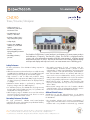
Technical Specifications: CNT-90 All measurements are displayed with a large main parameter value and smaller auxiliary parameter values (with less resolution). Some measurements are only available as auxiliary parameters. Frequency A, B, C Range: Input A, B: 0.002 Hz to 400 MHz Input C (option): Up to 3, 8, 15 or 20 GHz Resolution: 12 digits in 1s measuring time (normal) Aux. Parameter (A, B): Vmax, Vmin, Vp-p Frequency Burst A, B, C (opt. 14/14B) Frequency and PRF of repetitive burst signals can be measured without external control signal and with selectable start arming delay. Functions: Frequency in burst (in Hz); PRF (in Hz) Range: Input A, B, C: See Frequency spec. Minimum Burst Duration: Down to 40 ns Minimum Pulses in Burst: Input A or B: 3 (6 above 160 MHz) Input C: 3 x prescaler factor PRF Range: 0.5 Hz to 1MHz Start Delay: 10 ns to 2sec., 10 ns resolution Aux. Parameter: PRF Period A, B, C Mode: Single, Average Range: Input A, B: 2.5 ns to 1000 sec. (single, average) Input C (option): 10 ns down to 330, 125, 70 or 50 ps Resolution: 100 ps (single); 12 digits/s (avg) Aux. Parameter (A, B): Vmax, Vmin, Vp-p Ratio A/B, B/A, C/A, C/B Range: (10-9) to 1011 Input Frequency: Input A, B: 0.1 Hz to 400 MHz Input C (option): Up to 3, 8, 15 or 20 GHz Aux Parameters: Freq 1, Freq 2 Time Interval A to B, B to A, A to A, B to B Range: Normal Calculation: 0ns to +10 sec. Smart Calculation: -106 sec. to +106 sec. Resolution: 100 ps Min. Pulse Width: 1.6 ns Smart Calculation: Smart Time Interval to determine sign (A before B or A after B) 6 Positive and Negative Pulse Width A, B Range: 2.3 ns to 106 sec. Min. Pulse Width: 2.3 ns Aux. Parameters: Vmax,Vmin, Vp-p Rise and Fall Time A, B Range: 1.5 ns to 106 sec. Trigger Levels: 10% and 90% of signal Vp-p Min. Pulse Width: 1.6 ns Aux. Parameters: Slew rate, Vmax, Vmin Positive and Negative Duty Factor A, B Range: 0.000001 to 0.999999 Freq. Range: 0.1 Hz to 300 MHz Aux. parameters: Period, pulse width Phase A Relative B, B Relative A Range: -180° to +360° Resolution: Single-cycle: 0.001° to 10 kHz, decreasing to 1° >10 MHz. Resolution can be improved via averaging (statistics) Freq. Range: up to 160 MHz Aux. Parameters: Freq (A), Va/Vb (in dB) Vmax, Vmin, Vp-p A, B Range: -50 V to +50 V, -5V to +5V Range is limited by the specification for max input voltage without damage (see input A, B) Freq. Range: DC, 1Hz to 300 MHz Mode: Vmax, Vmin, Vp-p Resolution: 2.5 mV Uncertainty (5V range, typical): DC, 1Hz to 1kHz: 1% +15 mV 1kHz to 20 MHz: 3% +15 mV 20 to 100 MHz: 10% +15 mV 100 to 300 MHz: 30% +15 mV Aux parameters: Vmin, Vmax, Vp-p Time stamping A, B, C Raw time stamp data together with pulse counts on inputs A, B or C, accessible via GPIB or USB only. Max Sample Speed: See GPIB specifications Max Frequency: 160 MHz Timestamp Resolution: 70 ps Input and Output Specifications Inputs A and B Frequency Range: DC-Coupled: DC to 400 MHz AC-Coupled: 10 Hz to 400 MHz Impedance: 1M // 20 pF or 50 (VSWR 2:1) Trigger Slope: Positive or negative Max. Channel Timing Difference: 500 ps Sensitivity: DC-200 MHz: 15 mVrms 200-300 MHz: 25 mVrms 300-400 MHz: 35 mVrms Attenuation: x1, x10 Dynamic Range (x1): 30 mV p-p to 10 V p-p within ±5V window Trigger Level: Read-Out on display Resolution: 3mV Uncertainty (x1): ±(15 mV + 1% of trigger level) AUTO Trigger Level: Trigger level is automatically set to 50% point of input signal (10% and 90% for Rise/Fall Time) AUTO Hysteresis: Freq. range: 1Hz to 300 MHz Time: Min hysteresis window (hysteresis compensation) Frequency: One third of input signal amplitude Analog LP Filter: Nominal 100kHz, RC-type. Digital LP Filter: 1Hz to 50 MHz cut-off frequency Max Voltage Without Damage: 1M: 350 V (DC + AC pk) to 440 Hz, falling to 12 Vrms at 1MHz. 50 : 12 Vrms Connector: BNC Input C (Option 10) Operating Input Voltage Range opt. 10: 100 to 300 MHz: 20 mVrms (-21 dBm) to 12 Vrms 0.3 to 2.5 GHz: 10 mVrms (-27 dBm) to 12 Vrms 2.5 to 2.7 GHz: 20 mVrms (-21 dBm) to 12 Vrms 2.7 to 3.0 GHz: 40 mVrms (-15 dBm) to 12 Vrms Prescaler Factor: 16 Impedance: 50 nominal, VSWR <2.5:1 Max Voltage without Damage: 12 Vrms, pin-diode protected Connector: Type N Female Input C (Option 13) Operating Input Voltage Range: 100 to 200 MHz: 100 mVrms to 7Vrms (typ.) 200 to 300 MHz: 40 mVrms to 7Vrms (typ.) 300 to 500 MHz: 20 mVrms to 7Vrms 0.5 to 3.0 GHz: 10 mVrms to 7Vrms 3.0 to 4.5 GHz: 20 mVrms to 7Vrms 4.5 to 6.0 GHz: 40 mVrms to 7Vrms 6.0 to 8 GHz: 80 mVrms to 7Vrms Prescaler Factor: 256 Impedance: 50 nominal, VSWR <2.5:1 Max Voltage Without Damage: 7Vrms Connector: Type N Female Input C (Option 14 and 14B) Freq. Range: 0.25 to 15 GHz (opt. 14) 0.25 to 20 GHz (opt. 14B) Operating input voltage range: 250 to 500 MHz: -21 to +27 dBm 0.5 to 15 GHz: -27 to +27 dBm 15 to 18 GHz: -27 to +27 dBm (Option 14B only) 18 to 20 GHz: -21 to +27 dBm (Option 14B only) Prescaler Factor: 128 Typical sensitivity option 14B 0 -5 -10 -15 -20 dBm Measuring Functions -25 -30 -35 -40 -45 -50 0 5 10 15 20 25 GHz Typical Spec Impedance: 50 nominal, VSWR <2.0:1 AM tolerance: > 90% within sensitivity range Max Voltage Without Damage: +27 dBm Connector: Type precision N Female Rear Panel Inputs and Outputs Reference Input: 1, 5, or 10 MHz; 0.1 to 5Vrms sine; impedance 1k Reference Output: 10 MHz; >1Vrms sine into 50 Arming Input: Arming of all measuring functions Impedance: Approx. 1k Freq. Range: DC to 80 MHz Rear Panel Measurement Inputs: A, B, C (opt. 11/90) Impedance: 1M//50 pF or 50 (VSWR 2:1) Connectors: SMA female for rear input C, BNC for all other inputs/outputs Auxiliary Functions Trigger Hold-Off Time Delay Range: 20 ns to 2sec., 10 ns resolution External Start and Stop Arming Modes: Start, Stop, Start and Stop Arming Input Channels: A, B or E-rear panel Max Rep. Rate for Arming Signal: Channel A,B: 160 MHz Channel E: 80 MHz Start Time Delay Range: