1
User's Guide
Agilent 8504B
Precision
Reectometer
FINAL TRIM SIZE : 7.5 in x 9.0 in
Agilent part number: 08504-90055
Printed in USA July 2001
Lightwave Division
3910 Brickway Boulevard,
Santa Rosa, CA
95403, USA
Instrument Support Center: (800) 403-0801
Notice. The information contained in this document is subject to change
without notice. Agilent Technologies makes no warranty of any kind
with regard to this material, including but not limited to, the implied
warranties of merchantability and tness for a particular purpose. Agilent
Technologies shall not be liable for errors contained herein or for incidental or
consequential damages in connection with the furnishing, performance, or use
of this material.
Restricted Rights Legend. Use, duplication, or disclosure by the U.S.
Government is subject to restrictions as set forth in subparagraph (c) (1) (ii)
of the Rights in Technical Data and Computer Software clause at DFARS
252.227-7013 for DOD agencies, and subparagraphs (c) (1) and (c) (2) of the
Commercial Computer Software Restricted Rights clause at FAR 52.227-19 for
other agencies.
c Copyright Agilent Technologies 1992, 1993, 1994, 1995, 2001
All Rights Reserved. Reproduction, adaptation, or translation without prior
written permission is prohibited, except as allowed under the copyright laws.
FINAL TRIM SIZE : 7.5 in x 9.0 in
WARNING
This is a IEC Class 1 LED product. Do not stare into beam or view
directly with optical instruments. LED radiation is emitted from the
front-panel TEST PORT and REFERENCE EXTENSION A connectors.
WARNING
If this instrument is not used as specied, the protection provided by the
equipment could be impaired. This instrument must be used in a normal
condition (in which all means for protection are intact) only.
WARNING
No operator serviceable parts inside. Refer servicing to qualied
personnel. To prevent electrical shock and LED radiation, do not remove
covers.
CAUTION
Before switching on this product, make sure that the line-voltage selector
switch is set to the voltage of the power supply and the correct fuse is
installed. Assure the supply voltage is in the specied range.
CAUTION
Electrostatic discharge (ESD) can damage circuits associated with rear-panel
connectors. Therefore, before connecting any cable to a rear-panel connector,
momentarily short the center and outer conductors of the cable together.
Avoid touching the rear-panel connectors without rst touching the frame of
the instrument. Be sure that the instrument is properly earth-grounded to
prevent buildup of static charge.
This instrument has been designed and tested in accordance with IEC
Publication 348, Safety Requirements for Electronic Measuring Apparatus,
and has been supplied in a safe condition. The instruction documentation
contains information and warnings which must be followed by the user to
ensure safe operation and to maintain the instrument in a safe condition.
iii
FINAL TRIM SIZE : 7.5 in x 9.0 in
The 8504B at a glance
The 8504B precision reectometer is a high-resolution interferometer
that measures return loss. It is optimized for single-mode ber, but useful
measurements can also be made in multi-mode ber. The precision
reectometer performs measurements at 1300 nm and 1550 nm wavelengths.
Typical applications include:
Measurements of launch optics for lasers and opto-electronic integrated
circuits.
Measurements of passive ber-optic devices such as couplers, attenuators,
connectors, and isolators.
High-resolution measurements of lightwave path discontinuities based on a
known refractive index.
Measurement of refractive index of material based on a known distance
between two discontinuities.
High-resolution measurement of path length, expressed as transit time.
Measurements of bulk optic devices such as lenses, AR coatings, and
crystals.
iv
FINAL TRIM SIZE : 7.5 in x 9.0 in
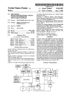
Using the precision reectometer, you can display multiple reections from
the device that you are testing. For example, the following gure shows an
LED device with ve reective surfaces. For each surface, the gure shows
the corresponding response on the precision reectometer's display.
v
FINAL TRIM SIZE : 7.5 in x 9.0 in
Guided procedures
reduce measurement
time
The precision reectometer provides guided setup and guided calibration
procedures that help you prepare the instrument for measurements.
These procedures consist of a series of screens that present step-by-step
instructions.
Procedure
guided setup
Task
Selects light source and calibrates the instrument for
pigtailed or non-pigtailed devices.
guided calibration
Calibrates the instrument.
You can also manually calibrate the instrument for maximum exibility.
Refer to Chapter 2 for a complete explaination of guided setups and guided
calibrations.
You should calibrate the instrument:
After the instrument has warmed up for 1 hour.
Before making any measurements.
Front-panel adapters
can be changed
The precision reectometer's three front-panel connectors are compatible
with 9/125 m ber-optic cables. All three connectors are adapters that can
be easily changed or removed for cleaning. Simply unscrew each adapter
in a counterclockwise direction. Useful measurements are achievable with
other adapters, but measurement performance may not be optimum. Refer
to \Front-Panel Fiber-Optic Adapters" in Chapter 5 for a complete listing of
available adapter types.
Softkeys select
instrument features
Many instrument features are available through the use of softkeys. Softkeys
are the eight keys that are located along the right-hand side of the display.
The denitions for these keys are shown on the display next to the key and
change for dierent menus.
vi
FINAL TRIM SIZE : 7.5 in x 9.0 in
Annotation Shown in the Display's \Status Notation" Area
Status
Notations
*
Avg
C
D
ext
Hld
OVL
Description
Measurement parameters changed: measured data is in doubt until a complete clean sweep has been taken.
Sweep-to-sweep averaging is on. The averaging count is shown immediately below this notation.
Error correction (measurement calibration) is on.
Dispersion correction is on. This notation is available for the 1550 nm source only.
Waiting for an external trigger at the rear panel.
Hold sweep.
Amplitude of reected signal at test port is too large.
vii
FINAL TRIM SIZE : 7.5 in x 9.0 in
front-panel knob
4G/n5
4M/5
4K/m5
4x15
4ENTRY OFF5
Allows continuous adjustments to current values for
various functions such as start value, scale, and others.
Values changed by the knob are eective immediately, and
require no units terminator.
Terminates numeric keypad entries with 106 multiplier.
Terminates numeric keypad entries with 106 multiplier.
Terminates numeric keypad entries with 106 multiplier.
Terminates unitless entries such as averaging factors.
Disables the keypad, knob, and step keys until another
function is selected.
9
6
3
viii
FINAL TRIM SIZE : 7.5 in x 9.0 in
Safety Symbols
CAUTION
WARNING
The following safety symbols are used throughout this manual. Familiarize
yourself with each of the symbols and its meaning before operating this
instrument.
The caution sign denotes a hazard to the instrument. It calls attention to a
procedure which, if not correctly performed or adhered to, could result in
damage to or destruction of the instrument. Do not proceed beyond a caution
sign until the indicated conditions are fully understood and met.
The warning sign denotes a life-threatening hazard. It calls attention to a
procedure which, if not correctly performed or adhered to, could result
in injury or loss of life. Do not proceed beyond a warning sign until the
indicated conditions are fully understood and met.
L
Instruction
Manual
j
CE
ISM1-A
CSA
The instruction manual symbol. The product is marked with this symbol when it is
necessary for the user to refer to the instructions in the manual.
The line-power on symbol.
The line-power o symbol.
The CE mark is a registered trademark of the European Community. (If accompanied by a
year, it is when the design was proven.)
This is a symbol of an Industrial Scientic and Medical Group 1 Class A product.
The CSA mark is a registered trademark of the Canadian Standards Association.
ix
FINAL TRIM SIZE : 7.5 in x 9.0 in
Certication and Assistance
Agilent Technologies certies that this product met its published specications
at the time of shipment from the factory. Agilent Technologies further
certies that its calibration measurements are traceable to the United States
National Institute of Standards and Technology (NIST), to the extent allowed
by the Institute's calibration facility, and to the calibration facilities of other
International Standards Organization members.
Product maintenance agreements and other customer assistance agreements
are available for Agilent Technologies products.
For any assistance, contact your nearest Agilent Technologies Sales and
Service Oce.
x
FINAL TRIM SIZE : 7.5 in x 9.0 in
Warranty
This Agilent Technologies instrument product is warranted against defects in
material and workmanship for a period of one year from date of shipment.
During the warranty period, Agilent Technologies will, at its option, either
repair or replace products which prove to be defective.
For warranty service or repair, this product must be returned to a service
facility designated by Agilent Technologies. Buyer shall prepay shipping
charges to Agilent Technologies and Agilent Technologies shall pay shipping
charges to return the product to Buyer. However, Buyer shall pay all shipping
charges, duties, and taxes for products returned to Agilent Technologies from
another country.
Agilent Technologies warrants that its software and rmware designated by
Agilent Technologies for use with an instrument will execute its programming
instructions when properly installed on that instrument. Agilent Technologies
does not warrant that the operation of the instrument, or software, or
rmware will be uninterrupted or error-free. Limitation of Warranty
The foregoing warranty shall not apply to defects resulting from improper
or inadequate maintenance by Buyer, Buyer-supplied software or
interfacing, unauthorized modication or misuse, operation outside of the
environmental specications for the product, or improper site preparation
or maintenance.
NO OTHER WARRANTY IS EXPRESSED OR IMPLIED. AGILENT
TECHNOLOGIES SPECIFICALLY DISCLAIMS THE IMPLIED WARRANTIES
OF MERCHANTABILITY AND FITNESS FOR A PARTICULAR PURPOSE.
Exclusive Remedies
THE REMEDIES PROVIDED HEREIN ARE BUYER'S SOLE AND EXCLUSIVE
REMEDIES. AGILENT TECHNOLOGIES SHALL NOT BE LIABLE FOR
ANY DIRECT, INDIRECT, SPECIAL, INCIDENTAL, OR CONSEQUENTIAL
DAMAGES, WHETHER BASED ON CONTRACT, TORT, OR ANY OTHER
LEGAL THEORY.
xi
FINAL TRIM SIZE : 7.5 in x 9.0 in
FINAL TRIM SIZE : 7.5 in x 9.0 in
Contents
1. Installing
.
.
.
.
.
.
.
.
.
.
.
.
.
.
.
.
.
.
.
.
.
.
.
.
.
.
.
.
.
.
.
.
.
.
.
.
.
.
.
.
.
.
1-4
1-5
1-7
1-10
1-11
1-19
1-21
1-23
1-24
1-24
1-25
1-26
1-27
1-29
Running Guided Setups and Calibrations . . . . . .
To perform a guided setup (devices with pigtail) .
To perform a guided setup (devices without pigtail)
To perform a guided calibration . . . . . . . . .
Performing Manual Calibrations . . . . . . . . . .
To balance the receiver . . . . . . . . . . . . .
To calibrate the magnitude . . . . . . . . . . .
To calibrate for an external source . . . . . . . .
To turn o calibration data . . . . . . . . . . .
To enter the standard's reection percentage . . .
To turn chromatic dispersion correction on and o .
To use the Option 001 cable tray . . . . . . . .
.
.
.
.
.
.
.
.
.
.
.
.
.
.
.
.
.
.
.
.
.
.
.
.
2-6
2-7
2-13
2-18
2-20
2-23
2-25
2-26
2-28
2-28
2-28
2-29
Step 1. Inspect the shipment . . . . . . . . .
Step 2. Connect the two instrument sections . .
Step 3. Set the line voltage . . . . . . . . . .
Step 4. Connect the rear-panel cables . . . . .
Step 5. Verify Operation . . . . . . . . . . .
To replace the line fuse . . . . . . . . . . . .
Cleaning Connections for Accurate Measurements
To clean a non-lensed connector . . . . . . .
To clean an adapter . . . . . . . . . . . .
To test insertion loss . . . . . . . . . . . .
To test return loss . . . . . . . . . . . . .
Returning Your Instrument . . . . . . . . . .
To return the instrument for service . . . . .
Agilent Technologies Sales and Service Oces . .
2. Performing Guided Setups and Calibrations
.
.
.
.
.
.
.
.
.
.
.
.
.
.
Contents-1
FINAL TRIM SIZE : 7.5 in x 9.0 in
3. Performing Measurements
Setting the Measurement Range . . .
To select the source wavelength . .
To automatically tune to a response
To change the displayed scale . . .
To change the refractive index . .
Reducing Displayed Noise . . . . .
.
.
.
.
.
.
.
.
.
.
.
.
.
.
.
.
.
.
.
.
.
.
.
.
.
.
.
.
.
.
.
.
.
.
.
.
.
.
.
.
.
.
.
.
.
.
.
.
.
.
.
.
.
.
Using Markers . . . . . . . . . . . . . . . . .
To display a peak response . . . . . . . . . . .
To change the measurement range . . . . . . . .
To make relative measurements . . . . . . . . .
To position a xed reference marker . . . . . . .
To change the peak denition . . . . . . . . . .
To turn markers o . . . . . . . . . . . . . .
Creating Limit Lines . . . . . . . . . . . . . . .
To enter limit-line segments . . . . . . . . . . .
To display or hide limit lines . . . . . . . . . .
To turn on limit testing . . . . . . . . . . . .
Tutorial: Using Limit Lines . . . . . . . . . . .
Storing Traces to Memory . . . . . . . . . . . .
To view memory traces . . . . . . . . . . . . .
Saving Instrument States to Registers . . . . . . .
To save to a register . . . . . . . . . . . . . .
To recall a register . . . . . . . . . . . . . . .
To increase user memory . . . . . . . . . . . .
Saving Instrument States to Files . . . . . . . . .
To save to a disk . . . . . . . . . . . . . . .
To change a le name . . . . . . . . . . . . .
To recall an external le . . . . . . . . . . . .
To delete an external le . . . . . . . . . . . .
To format an external disk . . . . . . . . . . .
To connect a disk drive . . . . . . . . . . . . .
Changing Colors and Audible Warnings . . . . . .
To adjust displayed colors . . . . . . . . . . .
To turn on the warning beep . . . . . . . . . .
To turn o the \done" beep . . . . . . . . . .
Printing and Plotting . . . . . . . . . . . . . .
To print the display . . . . . . . . . . . . . .
To plot the display . . . . . . . . . . . . . .
To print or plot measurement and parameter values
.
.
.
.
.
.
.
.
.
.
.
.
.
.
.
.
.
.
.
.
.
.
.
.
.
.
.
.
.
.
.
.
.
.
.
.
.
.
.
.
.
.
.
.
.
.
.
.
.
.
.
.
.
.
.
.
.
.
.
.
.
.
.
.
.
.
To reduce the displayed noise . . . . . . . . . . . . .
Contents-2
FINAL TRIM SIZE : 7.5 in x 9.0 in
3-4
3-6
3-7
3-7
3-8
3-9
3-11
3-12
3-16
3-16
3-16
3-17
3-17
3-18
3-19
3-23
3-23
3-24
3-25
3-34
3-35
3-36
3-38
3-38
3-39
3-40
3-41
3-42
3-43
3-43
3-43
3-44
3-45
3-45
3-45
3-46
3-47
3-48
3-48
3-49
To enter the printer/plotter type and address . . . . .
To abort a print or plot . . . . . . . . . . . . . . . .
4. Programming
3-49
3-50
.
.
.
.
.
.
.
.
.
.
.
.
.
.
.
.
.
.
.
.
.
.
.
.
.
.
.
.
.
.
.
.
.
.
.
.
.
.
.
.
.
.
.
.
.
.
.
.
.
.
.
.
.
.
.
.
.
.
.
.
.
.
.
.
.
.
.
.
.
.
.
.
.
.
.
.
.
4-4
4-8
4-8
4-9
4-12
4-15
4-54
.
.
.
.
.
.
.
.
.
.
.
.
.
.
.
.
.
.
.
.
.
.
.
.
.
.
.
.
.
.
.
.
.
.
.
.
.
.
.
.
.
.
.
.
.
.
.
.
.
.
.
.
.
.
.
.
.
.
.
.
.
.
.
.
.
.
.
.
.
.
.
.
.
.
.
.
.
5-3
5-11
5-52
5-53
5-54
5-55
5-56
.
.
.
.
.
.
.
.
.
.
.
.
.
.
.
.
.
.
.
.
.
.
.
.
.
.
.
.
.
.
.
.
.
.
.
.
.
.
.
.
.
.
.
.
.
.
.
.
.
.
.
.
.
.
.
.
.
.
.
.
.
.
.
.
.
.
.
.
.
.
.
.
.
.
.
.
.
6-4
6-4
6-5
6-6
6-8
6-9
6-10
6-12
6-14
6-16
6-16
Message Denitions . . . . . . . . . . . . . . . . .
Error Message Numbers . . . . . . . . . . . . . . .
7-3
7-11
Controlling the Instrument . . .
To select the HP-IB mode . .
To change the HP-IB address .
Monitoring the Instrument . . .
IEEE 488.2 Common Commands
Instrument Commands . . . . .
Keys versus Commands . . . .
5. Reference
Menu Maps . . . . . . . . . .
Keys, Softkeys, and Connectors .
Block Diagram . . . . . . . .
Front-Panel Fiber-Optic Adapters
Part Numbers . . . . . . . . .
Instrument Options . . . . . .
Line-Power Cables . . . . . . .
6. Specications and Regulatory Information
Specications . . . . . . . . . . . .
LED Classication . . . . . . . . .
Return Loss Measurement Range . .
Return Loss Uncertainty . . . . . .
Sweep-to-Sweep Repeatability . . . .
Two-Event Spatial Accuracy . . . .
Two-Event Spatial Resolution . . . .
Spurious Responses . . . . . . . .
Characteristics . . . . . . . . . . .
Regulatory Information . . . . . . .
Notice for Germany: Noise Declaration
7. Error Messages
.
.
.
.
.
.
.
.
.
.
.
Index
Contents-3
FINAL TRIM SIZE : 7.5 in x 9.0 in
Contents
FINAL TRIM SIZE : 7.5 in x 9.0 in
1
Installing
FINAL TRIM SIZE : 7.5 in x 9.0 in
Installing
This chapter shows you how to install your precision reectometer and how
to verify that it is operating properly. Be sure to save the shipping containers
in the event that the instrument should need to be returned to HP. It is
important to have the correct packaging.
Refer to Chapter 6 for information on operating conditions such as
temperature.
If you should ever need to clean the cabinet, use a damp cloth only.
WARNING
For continued protection against re hazard, replace line fuse only with
same type and ratings. The use of other fuses or materials is prohibited.
The correct fuse types are listed on the rear panel of each instrument
section.
WARNING
If this product is to be energized via an external autotransformer for
voltage reduction, make sure that its common terminal is connected to a
neutral (earthed pole) of the power supply.
CAUTION
When installing the product in a cabinet, the convection into and out of
the product must not be restricted. The ambient temperature (outside
the cabinet) must be less than the maximum operating temperature of
the product by 4 C for every 100 watts dissipated in the cabinet. If the
total power dissipated in the cabinet is greater than 800 watts, then forced
convection must be used.
CAUTION
This product is designed for use in INSTALLATION CATEGORY II and
POLLUTION DEGREE 2, per IEC 1010 and 664 respectively.
1-2
FINAL TRIM SIZE : 7.5 in x 9.0 in
Installing
Contents
Step 1. Inspect the shipment : : : : : : : : : : : : : : : : : : : : : : : : : : : : : : : : : : : : : : : : : : : 1-4
Step 2. Connect the two instrument sections : : : : : : : : : : : : : : : : : : : : : : : : : : : 1-5
Step 3. Set the line voltage : : : : : : : : : : : : : : : : : : : : : : : : : : : : : : : : : : : : : : : : : : : : : 1-7
Step 4. Connect the rear-panel cables : : : : : : : : : : : : : : : : : : : : : : : : : : : : : : : : : 1-10
Step 5. Verify Operation : : : : : : : : : : : : : : : : : : : : : : : : : : : : : : : : : : : : : : : : : : : : : : : 1-11
To replace the line fuse : : : : : : : : : : : : : : : : : : : : : : : : : : : : : : : : : : : : : : : : : : : : : : : : 1-19
Cleaning Connections for Accurate Measurements : : : : : : : : : : : : : : : : : : : : : 1-21
To clean a non-lensed connector : : : : : : : : : : : : : : : : : : : : : : : : : : : : : : : : : : : : 1-23
To clean an adapter : : : : : : : : : : : : : : : : : : : : : : : : : : : : : : : : : : : : : : : : : : : : : : : : : 1-24
To test insertion loss : : : : : : : : : : : : : : : : : : : : : : : : : : : : : : : : : : : : : : : : : : : : : : : : 1-24
To test return loss : : : : : : : : : : : : : : : : : : : : : : : : : : : : : : : : : : : : : : : : : : : : : : : : : : 1-25
Returning Your Instrument : : : : : : : : : : : : : : : : : : : : : : : : : : : : : : : : : : : : : : : : : : : : : 1-26
To return the instrument for service : : : : : : : : : : : : : : : : : : : : : : : : : : : : : : : : 1-27
Agilent Technologies Sales and Service Oces : : : : : : : : : : : : : : : : : : : : : : : : : 1-29
1-3
FINAL TRIM SIZE : 7.5 in x 9.0 in
Step 1. Inspect the shipment
Verify that all system components ordered have arrived by comparing the
shipping forms to the original system purchase order. Inspect all shipping
containers.
If your shipment is damaged or incomplete, save the packing materials
and notify both the shipping carrier and the nearest Agilent Technologies
sales and service oce. Agilent will arrange for repair or replacement
of damaged or incomplete shipments without waiting for a settlement
from the transportation company. Notify the customer engineer of any
problems.
Precision Reectometer Accessories
Item
Quantity
Wood box
100 cm FC/PC ber-optic cable
Fiber-optic cable adapter1
Low-reection termination
Cotton swabs
Tape measure (3 m)
Rear-panel BNC cable
Rear-panel IO INTERCONNECT cable
Rear-panel line-power cable
1
2
1
1
1
1
1
1
1
Cable tray
Fiber-optic cable adapter1
40 cm FC/PC ber-optic cable
50 cm FC/PC ber-optic cable
75 cm FC/PC ber-optic cable
125 cm FC/PC ber-optic cable
150 cm FC/PC ber-optic cable
175 cm FC/PC ber-optic cable
1
1
2
2
2
2
2
2
Standard:
Option 001 Accessory Kit:
1 Used to connect two FC/PC ber-optic cables.
1-4
FINAL TRIM SIZE : 7.5 in x 9.0 in
Step 2. Connect the two instrument sections
WARNING
Always disconnect and separate the two instrument sections before lifting
or moving the instrument. Otherwise, you may harm yourself or damage
the instrument.
1. Verify that serial number labels on the two instrument sections contain
the same serial number. You'll nd these labels on the precision
reectometer's rear panel. Make sure that the serial number and options
listed on the labels match the serial number and options listed on the
shipping document.
2. Place the lightwave section on a steady, sturdy work surface.
3. Place the display processor on top of the lightwave section so that the
front edge of the display processor is about 0.6 cm (0.25 in) in front of the
lightwave section.
4. Slightly lift the rear of the display processor and slide it back until its front
edge is even with the front edge of the lightwave section.
1-5
FINAL TRIM SIZE : 7.5 in x 9.0 in
Installing
Step 2. Connect the two instrument sections
Hooks on the top of the lightwave section will slide into slots on the
display processor and lock the front panels of the two sections together.
5. Conrm that the two instruments are locked together by very gently lifting
up on the front of the display processor. If the display processor separates
from the lightwave section, they are not locked together properly.
6. Tighten the rear-panel thumbscrews on the locking feet.
7. Ensure that there is a minimum of seven centimeters (three inches) free
space around the instrument to provide for adequate cooling.
1-6
FINAL TRIM SIZE : 7.5 in x 9.0 in
Step 3. Set the line voltage
CAUTION
Severe damage to the instrument can result if line voltage settings are
incorrect when power is applied.
1. Determine the line voltage of the AC power source. The line-power cords
should not be connected to the precision reectometer at this time.
2. Use a small at-blade screwdriver to set the display processor's
line-voltage selector switch to the value determined in step 1.
3. Use a small at-blade screwdriver to open the display processor's pull-out
fuse drawer. See the following gure.
1-7
FINAL TRIM SIZE : 7.5 in x 9.0 in
Installing
Step 3. Set the line voltage
4. Verify that the value of the line-voltage fuse in the pull-out drawer is
correct. The recommended fuse for both line-switch settings is a F3.0A,
250V, part number 2110-0780.
Notice that an extra fuse is provided in a drawer located on the fuse
holder.
5. On the lightwave section, use a at-blade screwdriver to pry open the
line module cover door. The cover door is hinged on the left side. Pry
beneath the tag that is located along the cover door's right-side edge. See
the following gure
1-8
FINAL TRIM SIZE : 7.5 in x 9.0 in
Installing
Step 3. Set the line voltage
CAUTION
Do not attempt to rotate the voltage selector cam while it is installed in
the line module or non-repairable damage will result. The cam must be
completely removed from the line module, rotated to the proper position, and
reinstalled.
6. Remove the voltage selector cam from the line module.
7. Rotate the voltage selector cam to the desired voltage. When the line
module cover is closed, the selected voltage will be visible through a
small window.
8. Insert the voltage selector cam back into the line module.
9. Verify that the value of the line-voltage fuse in the pull out draw is
correct.
The recommended fuse for 100V and 120V operation is a F1.5A, 250V,
part number 2110-0043. The recommended fuse for 220V and 240V
operation is a F0.75A, 250V, part number 2110-0063.
10. Close the line-module cover door.
1-9
FINAL TRIM SIZE : 7.5 in x 9.0 in
Step 4. Connect the rear-panel cables
WARNING
This is a Safety Class 1 Product (provided with a protective earthing
ground incorporated in the power cord). The mains plug shall only be
inserted in a socket outlet provided with a protective earth contact.
Any interruption of the protective conductor inside or outside of the
instrument is likely to make the instrument dangerous. Intentional
interruption is prohibited.
CAUTION
Always use the three-prong AC power cord supplied with this instrument.
Failure to ensure adequate earth grounding by not using this cord may cause
instrument damage.
1. Connect the I/O interconnect cable between the display processor and the
lightwave section.
2. Connect the BNC cable between the display processor and the lightwave
section.
3. Connect the power cable to display processor and the lightwave section.
1-10
FINAL TRIM SIZE : 7.5 in x 9.0 in
Step 5. Verify Operation
This step takes approximately 20 minutes to complete.
Equipment Required
The following equipment is supplied with the precision reectometer.
Two 100 cm FC/PC ber-optic cables.
One ber-optic cable coupling adapter.
One low-reection ber-optic termination.
Tighten connectors properly
Over-tightening or under-tightening connectors can result in misalignment and nonrepeatable
measurements. Always nger tighten connectors in a consistent manner. Refer to the manufacturer's
data sheet for any torque recommendations.
1. Turn the precision reectometer on, and allow it to warm up for at least
one hour.
2. Clean all cable connectors and front-panel optical ports.
Refer to \Cleaning Connections for Accurate Measurements" for
information on cleaning connectors.
3. Attach one of the 100 cm ber-optic cables to the front-panel TEST PORT
connector.
When mating Super PC connectors, check to see that the keyways on
the Super PC cable connectors are inserted into the slots on the mating
connectors.
4. If there is a protective cap on the free end of the ber-optic cable, remove
it.
5. Attach the other 100 cm ber-optic cable between the front-panel
REFERENCE EXTENSION connectors A and B.
1-11
FINAL TRIM SIZE : 7.5 in x 9.0 in
Installing
Step 5. Verify Operation
The REFERENCE EXTENSION and TEST PORT ber-optic cables must be
equal in length in order for reections to be viewed on the display.
6. Press 4PRESET5.
The wavelength defaults to 1300 nm.
NOTE
Do not move the reference extension cable for the rest of this procedure. Any movement of this cable
will change the reference signal polarization and will invalidate the calibration.
1-12
FINAL TRIM SIZE : 7.5 in x 9.0 in
Installing
Step 5. Verify Operation
7. Press 4CAL5 and then GUIDED CAL .
NNNNNNNNNNNNNNNNNNNNNNNNNNNNNNNN
8. Use the supplied adapter to connect the low-reection termination to the
open end of the TEST PORT cable.
Do not connect the termination to the front-panel connector as
suggested on the screen.
Low Reection Termination
9. Adjust the two front-panel REFERENCE POLARIZATION BALANCE knobs
until the line is in the shaded area. See the following gure.
10. Press DONE .
NNNNNNNNNNNNNN
11. Disconnect the low-reection termination from the ber-optic cable.
12. Press FRESNEL and then MEASURE STANDARD .
NNNNNNNNNNNNNNNNNNNNNNN
NNNNNNNNNNNNNNNNNNNNNNNNNNNNNNNNNNNNNNNNNNNNNNNNNN
The end of the cable is providing a Fresnel standard.
13. Wait until the asterisk on the display's left-hand side disappears and the
letter C remains below the asterisk.
1-13
FINAL TRIM SIZE : 7.5 in x 9.0 in
Installing
Step 5. Verify Operation
14. You should see a Fresnel response on the display due to a reection from
the end of the test port cable. If the response is missing, check the
following, and repeat this procedure from the beginning:
Are the the front-panel cables properly connected?
Are the rear-panel cables attached to the correct connectors?
Fresnel response.
15. Press 4MKR FCTN5, MAX SEARCH , and then MKR ZOOM .
NNNNNNNNNNNNNNNNNNNNNNNNNNNNNNNN
NNNNNNNNNNNNNNNNNNNNNNNNNN
This expands the display around the Fresnel response. Wait for the
response to move to the center of the display.
16. Press MAX SEARCH , and read the marker's amplitude value on the
display. If the value is not within the values shown below, thoroughly
clean all connectors on the cables and front panel, and repeat this
procedure from step 1.
Peak value (1300 nm source) : : : : : : : : : : : : : : : : : : : : : : : : : : 015 dB 60.5 dB
Peak value (1550 nm source) : : : : : : : : : : : : : : : : : : : : : : : : 014.7 dB 60.5 dB
NNNNNNNNNNNNNNNNNNNNNNNNNNNNNNNN
1-14
FINAL TRIM SIZE : 7.5 in x 9.0 in
Installing
Step 5. Verify Operation
Marker showing peak value with 1300 nm source.
17. Connect a coupling adapter to the end of the TEST PORT ber-optic cable.
1-15
FINAL TRIM SIZE : 7.5 in x 9.0 in
Installing
Step 5. Verify Operation
18. Partially insert the connector of another cable into the adapter. Observe
the Fresnel reection of this connector as you insert the cable.
19. Repeatedly press MKR ZOOM as you slowly insert the connector into the
adapter until the span is 1 mm. The Fresnel response should be as close
to the original response as possible and can still be resolved. See the
following gure.
NNNNNNNNNNNNNNNNNNNNNNNNNN
1-16
FINAL TRIM SIZE : 7.5 in x 9.0 in
Installing
Step 5. Verify Operation
Two responses viewed as a single signal.
20. Press 4MEAS5 and then TRIGGER:HOLD to freeze the trace.
NNNNNNNNNNNNNNNNNNNNNNNNNNNNNNNNNNNNNN
21. Press 4MKR FCTN5, MAX SEARCH , and then MARKER ! FIXED MKR to
turn on the delta marker and to reference the xed marker to zero on one
of the peaks.
22. Turn the front-panel knob to center the marker on the other peak.
23. The displayed spatial resolution shown in the marker area should be less
than the following values:
1300 nm source : : : : : : : : : : : : : : : : : : : : : : : : : : : : : : : : : : : : : : : : : : : : : 0.025 mm
1550 nm source : : : : : : : : : : : : : : : : : : : : : : : : : : : : : : : : : : : : : : : : : : : : : : : 0.25 mm
NNNNNNNNNNNNNNNNNNNNNNNNNNNNNNNN
NNNNNNNNNNNNNNNNNNNNNNNNNNNNNNNNNNNNNNNNNNNNNNNNNNNNNNNNNN
1-17
FINAL TRIM SIZE : 7.5 in x 9.0 in
Installing
Step 5. Verify Operation
Delta marker showing spatial resolution.
24. Press 4PRESET5.
25. Press 4MENU5 and then 1550 nm .
NNNNNNNNNNNNNNNNNNNNNNN
26. Remove the coupling adapter from the ber-optic cable, and repeat this
procedure from step 7 to check the operation at 1550 nm.
1-18
FINAL TRIM SIZE : 7.5 in x 9.0 in
To replace the line fuse
To change the fuse on the display processor section:
1. Disconnect the line-power cord from the display processor section.
2. Use a small at-blade screwdriver to open the pull-out fuse drawer as
shown in the following gure.
1-19
FINAL TRIM SIZE : 7.5 in x 9.0 in
Installing
To replace the line fuse
3. The recommended fuse for both line-switch settings is a F3.0A, 250V,
part number 2110-0780.
Notice that an extra fuse is provided in a drawer located on the fuse
holder.
To change the fuse on the lightwave section:
1. Disconnect the line-power cord from the lightwave section.
2. On the lightwave section, use a at-blade screwdriver to pry open the
line-module cover door. The cover door is hinged on the left side. Pry
beneath the tag that is located along the cover door's right-side edge.
See the following gure.
3. Pull out the fuse drawer. The following list shows the recommended
fuse:
100V and 120V operation : : : : : : : : : : : : : : : : F1.5A 250V (p/n 2110-0043)
220V and 240V operation : : : : : : : : : : : : : : : F0.75A 250V (p/n 2110-0063)
1-20
FINAL TRIM SIZE : 7.5 in x 9.0 in
Cleaning Connections for Accurate Measurements
CAUTION
Accurate and repeatable measurements require clean connections. Use the
following guidelines to achieve the best possible performance when making
measurements on a ber-optic system:
Keep connectors covered when not in use.
Use dry connections whenever possible.
Use the cleaning methods described in this section.
Use care in handling all ber-optic connectors.
When inserting a ber-optic connector into a front-panel adapter, make
sure that the ber end does not touch the outside of the mating connector
or adapter.
Because of the small size of cores used in optical bers, care must be used to
ensure good connections. Poor connections result from core misalignment, air
gaps, damaged ber ends, contamination, and improper use and removal of
index-matching compounds.
Use dry connections. Dry connectors are easier to clean and to keep clean.
Dry connections can be used with physically contacting connectors (for
example, Diamond HMS-10/HP, FC/PC, DIN, and ST). If a dry connection
has 40 dB return loss or better, making a wet connection will probably not
improve (and can degrade) performance.
Agilent Technologies strongly recommends that index matching compounds
NOT be applied to their instruments and accessories. Some compounds, such
as gels, may be dicult to remove and can contain damaging particulates. If
you think the use of such compounds is necessary, refer to the compound
manufacturer for information on application and cleaning procedures.
Cleaning Accessories
Item
Isopropyl alcohol
Cotton swabs
Small foam swabs
Compressed dust remover (non-residue)
Part Number
8500-5344
8520-0023
9300-1223
8500-5262
1-21
FINAL TRIM SIZE : 7.5 in x 9.0 in
Installing
Cleaning Connections for Accurate Measurements
Dust Caps Provided with Lightwave Instruments
Item
Laser shutter cap
FC/PC dust cap
DIN dust cap
HMS10/dust cap
ST dust cap
Part Number
08145-64521
08154-44102
5040-9364
08145-44101
1401-0291
Inspecting Fiber-Optic Consistent measurements with your lightwave equipment are a good
indication that you have good connections. However, you may wish to know
Cables
the insertion loss and/or return loss of your lightwave cables or accessories. If
you test your cables and accessories for insertion loss and return loss upon
receipt, and retain the measured data for comparison, you will be able to tell
in the future if any degradation has occurred.
Connector (or insertion) loss is one important performance characteristic of a
lightwave connector. Typical values are less than 1 dB of loss, and sometimes
as little as 0.1 dB of loss with high performance connectors. Return loss
is another important factor. It is a measure of reection: the less reection
the better (the larger the return loss, the smaller the reection). The best
physically contacting connectors have return losses better than 50 dB,
although 30 to 40 dB is more common.
You can visually inspect your cables
Although it is not necessary, visual inspection of ber ends can be helpful. Contamination or
imperfections on the cable end face can be detected as well as cracks or chips in the ber itself. Use
a microscope (100X to 200X magnication) to inspect the entire end face for contamination, raised
metal, or dents in the metal as well as any other imperfections. Inspect the ber for cracks and chips.
Visible imperfections not touching the ber core may not aect performance (unless the imperfections
keep the bers from contacting).
1-22
FINAL TRIM SIZE : 7.5 in x 9.0 in
Installing
Cleaning Connections for Accurate Measurements
To clean a non-lensed connector
CAUTION
Do not use any type of foam swab to clean optical ber ends. Foam swabs
can leave lmy deposits on ber ends that can degrade performance.
1. Apply isopropyl alcohol to a clean lint-free cotton swab or lens paper.
Cotton swabs can be used as long as no cotton bers remain on the ber
end after cleaning.
2. Before cleaning the ber end, clean the ferrules and other parts of the
connector.
3. Apply isopropyl alcohol to a new clean lint-free cotton swab or lens paper.
4. Clean the ber end with the swab or lens paper. Move the swab or lens
paper back and forth across the ber end several times.
Some amount of wiping or mild scrubbing of the ber end can help
remove particles when application of alcohol alone will not remove
them. This technique can remove or displace particles smaller than one
micron.
5. Immediately dry the ber end with a clean, dry, lint-free cotton swab or
lens paper.
6. Blow across the connector end face from a distance of 6 to 8 inches using
ltered, dry, compressed air. Aim the compressed gas at a shallow angle to
the ber end face.
Nitrogen gas or compressed dust remover can also be used.
CAUTION
Do not shake, tip, or invert compressed air canisters, because this releases
particles in the can into the air. Refer to instructions provided on the
compressed air canister.
7. As soon as the connector is dry, connect or cover it for later use.
1-23
FINAL TRIM SIZE : 7.5 in x 9.0 in
Installing
Cleaning Connections for Accurate Measurements
To clean an adapter
1. Apply isopropyl alcohol to a clean foam swab.
Cotton swabs can be used as long as no cotton bers remain after
cleaning. The foam swabs listed in this section's introduction are small
enough to t into adapters.
Although foam swabs can leave lmy deposits, these deposits are very
thin, and the risk of other contamination buildup on the inside of
adapters greatly outweighs the risk of contamination by foam swabs.
2. Clean the adapter with the foam swab.
3. Dry the inside of the adapter with a clean, dry, foam swab.
4. Blow through the adapter using ltered, dry, compressed air.
Nitrogen gas or compressed dust remover can also be used.
CAUTION
Do not shake, tip, or invert compressed air canisters, because this releases
particles in the can into the air. Refer to instructions provided on the
compressed air canister.
To test insertion loss
Use an appropriate lightwave source and a compatible lightwave receiver to
test insertion loss. Examples of test equipment congurations include the
following equipment:
HP 71450A or HP 71451A optical spectrum analyzers with Option 002
built-in white light source.
8702 or 8703 lightwave component analyzer system
83420 lightwave test set with an 8510 network analyzer
8153 lightwave multimeter with a source and power sensor module
1-24
FINAL TRIM SIZE : 7.5 in x 9.0 in
Installing
Cleaning Connections for Accurate Measurements
To test return loss
Use an appropriate lightwave source, a lightwave receiver, and lightwave
coupler to test return loss. Examples of test equipment congurations include
the following equipment:
8703 lightwave component analyzer
8702 analyzer with the appropriate source, receiver, and lightwave coupler
8504 precision reectometer
8153 lightwave multimeter with a source and power sensor module in
conjunction with a lightwave coupler
81554SM dual source and 81534A return loss module
1-25
FINAL TRIM SIZE : 7.5 in x 9.0 in
Returning Your Instrument
CAUTION
It is unlikely that your precision reectometer should need to be returned
to Agilent Technologies. However, if you do need to return it, repackage
the instrument using the original shipping containers and materials or their
equivalents. Agilent Technologies oces can provide packaging materials
identical to the original materials.
Packaging materials not specied can result in instrument damage. Never
use styrene pellets to package electronic instruments. The pellets do not
adequately cushion the instrument, do not prevent all instrument movement,
and can generate static electricity.
1-26
FINAL TRIM SIZE : 7.5 in x 9.0 in
Installing
Returning Your Instrument
To return the instrument for service
1. Fill out the repair form (located on the next page), and place it in the box
with the instrument. Send a copy of any noted error messages or other
helpful performance data.
2. To help prevent damage during transit, pack the instrument in the
factory packaging materials. Although the original shipping materials
or equivalents are best; the following instructions result in acceptable
packaging:
a. Wrap the instrument in anti-static plastic to reduce the possibility of
ESD damage.
b. For instruments that weigh less than 54 kg (120 lb), use a
double-walled, corrugated cardboard carton of 159 kg (350 lb) test
strength. The carton must be both large enough and strong enough to
accommodate the instrument. Allow at least three to four inches on all
sides of the instrument for packing material.
c. Surround the equipment with three to four inches of packing material
to protect the module and to prevent movement in the carton. If
packing foam is not available, the best alternative is S.D.-240 Air Cap
from Sealed Air Corporation, Hayward, California 94545. Air Cap is
plastic sheeting lled with 1-1/4 inch air bubbles. Use pink anti-static
Air Cap. Wrapping the instrument several times in this material should
provide sucient protection and also prevent movement in the carton.
3. Seal the carton with strong nylon adhesive tape.
4. Mark the carton FRAGILE, HANDLE WITH CARE.
5. Retain copies of all shipping papers.
TM
1-27
FINAL TRIM SIZE : 7.5 in x 9.0 in
Installing
Returning Your Instrument
Service Repair Form
Date:
Company:
Address:
Technical contact person:
Phone:
Model number:
Serial number:
P.O. number:
Accessories returned with unit:
none cables(s) power cable adapter(s)
Service Needed:
calibration only repair repair and calibration
Other:
Other:
Failure symptoms and special control settings:
If unit is part of system, list model number(s) of other interconnected instruments:
1-28
FINAL TRIM SIZE : 7.5 in x 9.0 in
Agilent Technologies Sales and Service Oces
Before returning an instrument for service, call the Agilent Technologies
Instrument Support Center at (800) 403-0801, visit the Test and Measurement
Web Site at http://www.agilent.com/nd/assist, or call one of the numbers
listed below.
Agilent Technologies Sales and Service Oces
Oce Location
Austria
Belgium
Brazil
China
Denmark
Finland
France
Germany
India
Italy
Ireland
Japan
Korea
Mexico
Netherlands
Norway
Russia
Spain
Sweden
Switzerland
United Kingdom
United States and Canada
Phone Number
01/25125-7171
32-2-778.37.71
(11) 7297-8600
86 10 6261 3819
45 99 12 88
358-10-855-2360
01.69.82.66.66
0180/524-6330
080-34 35788
+39 02 9212 2701
01 615 8222
(81)-426-56-7832
82/2-3770-0419
(5) 258-4826
020-547 6463
22 73 57 59
+7-095-797-3930
(34/91) 631 1213
08-5064 8700
(01) 735 7200
01 344 366666
(800) 403-0801
1-29
FINAL TRIM SIZE : 7.5 in x 9.0 in
Installing
FINAL TRIM SIZE : 7.5 in x 9.0 in
2
Performing Guided Setups
and Calibrations
FINAL TRIM SIZE : 7.5 in x 9.0 in
Performing Guided Setups and Calibrations
This chapter shows you how to perform guided setups, guided calibrations,
and manual calibrations. Calibrating the precision reectometer consists
of balancing the receiver and then calibrating the magnitude. These two
procedures ensure maximum accuracy for your measurements. They remove
DC osets and polarization sensitivity. They also set a calibrated reference
level.
Guided setups not only calibrate the instrument, but they also select the
source and display instructions for both pigtailed and non-pigtailed devices.
Manually calibrating the instrument is generally faster that using the guided
calibration.
When the instrument is calibrated, the status indicator C
appears on the display's left-hand side.
2-2
FINAL TRIM SIZE : 7.5 in x 9.0 in
Performing Guided Setups and Calibrations
Contents
Running Guided Setups and Calibrations : : : : : : : : : : : : : : : : : : : : : : : : : : : : : : : : 2-6
To perform a guided setup (devices with pigtail) : : : : : : : : : : : : : : : : : : : : : 2-7
To perform a guided setup (devices without pigtail) : : : : : : : : : : : : : : : : : 2-13
To perform a guided calibration : : : : : : : : : : : : : : : : : : : : : : : : : : : : : : : : : : : : : 2-18
Performing Manual Calibrations : : : : : : : : : : : : : : : : : : : : : : : : : : : : : : : : : : : : : : : : 2-20
To balance the receiver : : : : : : : : : : : : : : : : : : : : : : : : : : : : : : : : : : : : : : : : : : : : : 2-23
To calibrate the magnitude : : : : : : : : : : : : : : : : : : : : : : : : : : : : : : : : : : : : : : : : : : 2-25
To calibrate for an external source : : : : : : : : : : : : : : : : : : : : : : : : : : : : : : : : : : 2-26
To turn o calibration data : : : : : : : : : : : : : : : : : : : : : : : : : : : : : : : : : : : : : : : : : : 2-28
To enter the standard's reection percentage : : : : : : : : : : : : : : : : : : : : : : : 2-28
To turn chromatic dispersion correction on and o : : : : : : : : : : : : : : : : : : 2-28
To use the Option 001 cable tray : : : : : : : : : : : : : : : : : : : : : : : : : : : : : : : : : : : 2-29
NOTE
In order to ensure a successful calibration, clean all ber-optic connectors prior to the calibration. Refer
to \Cleaning Connections for Accurate Measurements" in Chapter 1 in this chapter.
Some hardware is
required
You'll need the following hardware, supplied with 8504B, to calibrate the
instrument:
A set of cables (matched length).
A low-reection termination.
You can use any termination that has a return loss that is greater than
30 dB.
2-3
FINAL TRIM SIZE : 7.5 in x 9.0 in
Performing Guided Setups and Calibrations
Matched-length cables During calibrations and subsequent measurements, two cables must be
connected to the precision reectometer. One cable connects the device
ensure response is
being measured to the front-panel TEST PORT. The other cable connects the
visible
front-panel REFERENCE EXTENSION A and B connectors. The REFERENCE
EXTENSION cable must be equal in length (or slightly shorter) than the TEST
PORT cable.
The relative lengths of these two cables determine the position of the Fresnel
reection (from the end of the TEST PORT cable) on the screen. If the
REFERENCE EXTENSION cable is too long or too short, the measured response
may not be visible on the screen. This is shown in the following gure.
Cable lengths determine response position.
2-4
FINAL TRIM SIZE : 7.5 in x 9.0 in
Performing Guided Setups and Calibrations
Changing the span does Any calibration performed in less than full span is still valid after the start or
not aect calibrations stop values are changed. Likewise, a calibration performed in full span is still
valid after the start or stop values are changed.
Keep the reference cable stationary
Do not move the reference-extension cable connected between REFERENCE EXTENSION A and
B on the front during or after a calibration. Moving this cable changes the polarization and voids
the calibration. If you have an Option 001 accessory kit, use the kit's cable tray to help keep the
reference extension cable stationary.
Unlike the reference-extension cable, the test-port cable is unaected by changes in polarization due to
cable bending. Therefore, this cable may be moved without degrading the calibration.
Keep the balance knobs stationary
Do not move either of the front panel reference-polarization balance knobs after calibration. Moving
the knobs compromises the calibration.
2-5
FINAL TRIM SIZE : 7.5 in x 9.0 in
Running Guided Setups and Calibrations
This section shows you how to perform guided setups for pigtailed or
nonpigtailed devices. (A pigtail is a length of ber-optic cable which usually
terminates in a connector.) Guided setups can be started using either the
4PRESET5 or 4SYSTEM5 keys. Using the 4PRESET5 key has the advantage of
setting the instrument to a known state.
During a guided calibration, a polar vector display shows polarization
balance between two receivers in the instrument. After manually adjusting
the polarization balance using the front-panel knobs, the precision
reectometer mathematically compensates for any polarization imbalance
between the TEST PORT cable and the REFERENCE EXTENSION paths. To
complete the calibration, a standard cable of known reectance is used to
calibrate the magnitude. The displayed response is scaled to match the value
specied for the standard in percentage of reectance.
2-6
FINAL TRIM SIZE : 7.5 in x 9.0 in
Performing Guided Setups and Calibrations
Running Guided Setups and Calibrations
To perform a guided setup
(devices with pigtail)
1. Press 4PRESET5 and then GUIDED SETUP .
NNNNNNNNNNNNNNNNNNNNNNNNNNNNNNNNNNNNNN
2. Press a softkey to select the wavelength.
3. Press CLASSIFY DEVICE and then PIGTAIL .
NNNNNNNNNNNNNNNNNNNNNNNNNNNNNNNNNNNNNNNNNNNNNNN
Select cables
NNNNNNNNNNNNNNNNNNNNNNN
4. Press CONNECT CABLES .
NNNNNNNNNNNNNNNNNNNNNNNNNNNNNNNNNNNNNNNNNNNN
5. Measure the length of the device's pigtail. Include the length of any
additional cable used to connect the device to the front-panel TEST PORT
connector.
6. Based on the length measured in the preceding step, use the following
chart to assemble a ber-optic cable for the reference path.
2-7
FINAL TRIM SIZE : 7.5 in x 9.0 in
Performing Guided Setups and Calibrations
Running Guided Setups and Calibrations
Cable Lengths
Length of Path
for Tested Device1
40 | 65
50 | 75
75 | 100
90 | 115
100 | 125
115 | 140
125 | 150
140 | 165
150 | 175
165 | 190
175 | 200
190 | 215
200 | 225
215 | 240
Assemble this
Cable2
40
50
75
40 + 50
100
40 + 75
125
40 + 100
150
40 + 125
175
40 + 150
50 + 150
40 + 175
Length of Path
for Tested Device1
225 | 250
240 | 265
250 | 275
265 | 290
275 | 300
290 | 315
300 | 325
315 | 340
325 | 350
340 | 365
350 | 375
365 | 390
375 | 400
Assemble this
Cable2
50 + 175
40 + 50 + 150
75 + 175
40 + 50 + 175
100 + 175
40 + 75 + 175
175 + 125
40 + 100 + 175
150 + 175
40 + 125 + 175
75 + 100 + 175
40 + 150 + 175
50 + 150 + 175
1 Lengths are in centimeters.
2 Standard length cables from Option 001 accessory kit. Lengths are in centimeters.
7. Connect the cables assembled in the preceding step between front-panel
REFERENCE EXTENSION connectors A and B.
If you have an Option 001 accessory kit, you can stabilize the cable
with the cable tray. Coil the cable around as necessary. If you are
using more than one cable, place the mid-connectors in the wide part
of the slot. Let the ends of the cable protrude from the tray. Be sure
to place the cover on the tray.
8. Connect your device to the front-panel TEST PORT.
Check setup
9. Press CHECK SETUP .
NNNNNNNNNNNNNNNNNNNNNNNNNNNNNNNNNNN
10. Wait for one full measurement sweep to complete.
2-8
FINAL TRIM SIZE : 7.5 in x 9.0 in
Performing Guided Setups and Calibrations
Running Guided Setups and Calibrations
11. If a response is not visible, perform the following steps:
a. Press 4CAL5, CALIBRATE MENU , and then BALANCE RECEIVER .
b. Follow the prompts on the screen. Then press DONE .
c. Wait for one full sweep to complete.
d. Press 4AVG5 and then AVERAGING ON .
e. Wait for the instrument to average 16 sweeps.
On the left side of the graticule, the Avg number will count to 16.
f. Press 4SYSTEM5 and then GUIDED SETUP , and follow the prompts on
the screen.
12. Press CONNECT TERMINATION .
NNNNNNNNNNNNNNNNNNNNNNNNNNNNNNNNNNNNNNNNNNNN
NNNNNNNNNNNNNNNNNNNNNNNNNNNNNNNNNNNNNNNNNNNNNNNNNN
NNNNNNNNNNNNNN
NNNNNNNNNNNNNNNNNNNNNNNNNNNNNNNNNNNNNN
NNNNNNNNNNNNNNNNNNNNNNNNNNNNNNNNNNNNNN
NNNNNNNNNNNNNNNNNNNNNNNNNNNNNNNNNNNNNNNNNNNNNNNNNNNNNNNNNNN
13. Disconnect the device from the TEST PORT.
Connect termination
14. Connect the low-reection termination directly to the TEST PORT.
Low Reection Termination
15. Press BALANCE RECEIVER .
NNNNNNNNNNNNNNNNNNNNNNNNNNNNNNNNNNNNNNNNNNNNNNNNNN
2-9
FINAL TRIM SIZE : 7.5 in x 9.0 in
Performing Guided Setups and Calibrations
Running Guided Setups and Calibrations
Balance Receiver
16. Adjust the two polarization balance knobs until the line is in the shaded
area.
17. Press DONE .
NNNNNNNNNNNNNN
NOTE
After balancing the receiver, do not move the extension cable, or the balance knobs. Movement
degrades measurement accuracy.
2-10
FINAL TRIM SIZE : 7.5 in x 9.0 in
Performing Guided Setups and Calibrations
Running Guided Setups and Calibrations
Calibrate Magnitude
18. Disconnect the termination from the TEST PORT.
19. Connect a second cable that is the same length as the REFERENCE
EXTENSION cable to the TEST PORT.
The free end of this cable serves as the \Fresnel" cal standard. When
using the supplied cables, the free end of the cable functions as the
calibration standard. This is possible because the percentage of light
reected by that type of cable connector is known. For 1300 nm
measurements, the correct value is 15 dB (3.16%). For 1550 nm, the
correct value is 14.7 dB (3.37%). Other calibration standards (cables,
connectors, or devices) may have other reection values.
20. If you are using cables from the Option 001 accessory kit, press
FRESNEL . If you are using another standard, perform the following
steps:
a. Obtain the standard's reection return loss (in dB).
b. Enter this value using the USER STD softkey.
NNNNNNNNNNNNNNNNNNNNNNN
NNNNNNNNNNNNNNNNNNNNNNNNNN
21. Press MEASURE STANDARD , and wait for the standard to be measured.
NNNNNNNNNNNNNNNNNNNNNNNNNNNNNNNNNNNNNNNNNNNNNNNNNN
Connect Device Under 22. Disconnect the cable from the TEST PORT.
Test
23. Connect the device to be tested to the TEST PORT.
24. Press MEASURE DEVICE and then EXIT SETUP to complete the guided
setup and begin device measurements.
NNNNNNNNNNNNNNNNNNNNNNNNNNNNNNNNNNNNNNNNNNNN
NNNNNNNNNNNNNNNNNNNNNNNNNNNNNNNN
25. As you measure devices, observe the following suggestions:
2-11
FINAL TRIM SIZE : 7.5 in x 9.0 in
Performing Guided Setups and Calibrations
Running Guided Setups and Calibrations
Use the 4START5 and 4STOP5, 4CENTER5 and 4SPAN5, and marker keys to
optimize the displayed response.
Reducing the span increases measurement speed, improve
resolution, and increase dynamic range.
To improve the signal-to-noise ratio, use averaging. Turn on averaging
by pressing 4AVG5 and then AVERAGING on OFF so that ON is
highlighted.
NNNNNNNNNNNNNNNNNNNNNNNNNNNNNNNNNNNNNNNNNNNNNNNNNN
2-12
FINAL TRIM SIZE : 7.5 in x 9.0 in
NNNNNNNN
Performing Guided Setups and Calibrations
Running Guided Setups and Calibrations
To perform a guided setup
(devices without pigtail)
1. Press 4PRESET5 and then GUIDED SETUP .
NNNNNNNNNNNNNNNNNNNNNNNNNNNNNNNNNNNNNN
2. Press a softkey to select the wavelength.
3. Press CLASSIFY DEVICE and then NO PIGTAIL .
NNNNNNNNNNNNNNNNNNNNNNNNNNNNNNNNNNNNNNNNNNNNNNN
Select cables
NNNNNNNNNNNNNNNNNNNNNNNNNNNNNNNN
4. Press CONNECT CABLES .
NNNNNNNNNNNNNNNNNNNNNNNNNNNNNNNNNNNNNNNNNNNN
5. Locate two ber-optic cables that are of equal length.
6. Connect one of the cables between front-panel REFERENCE EXTENSION
connectors A and B.
If you have an Option 001 accessory kit, you can stabilize the cable
with the cable tray. Coil the cable around as necessary. If you are
using more than one cable, place the mid-connectors in the wide part
of the slot. Let the ends of the cable protrude from the tray. Be sure
to place the cover on the tray.
7. Connect the second ber-optic cable to the front-panel TEST PORT.
8. Connect your device to the TEST PORT cable.
Check setup
9. Press CHECK SETUP , and wait for one full measurement sweep to
complete.
NNNNNNNNNNNNNNNNNNNNNNNNNNNNNNNNNNN
2-13
FINAL TRIM SIZE : 7.5 in x 9.0 in
Performing Guided Setups and Calibrations
Running Guided Setups and Calibrations
10. If a response is not visible, perform the following steps:
a. Press 4CAL5, CALIBRATE MENU , and then BALANCE RECEIVER .
b. Follow the prompts on the screen. Then press DONE .
c. Wait for one full sweep to complete.
d. Press 4AVG5 and then AVERAGING ON .
e. Wait for the instrument to average 16 sweeps.
On the left side of the graticule, the Avg number will count to 16.
f. Press 4SYSTEM5 and then GUIDED SETUP , and follow the prompts on
the screen.
11. Press CONNECT TERMINATION .
NNNNNNNNNNNNNNNNNNNNNNNNNNNNNNNNNNNNNNNNNNNN
NNNNNNNNNNNNNNNNNNNNNNNNNNNNNNNNNNNNNNNNNNNNNNNNNN
NNNNNNNNNNNNNN
NNNNNNNNNNNNNNNNNNNNNNNNNNNNNNNNNNNNNN
NNNNNNNNNNNNNNNNNNNNNNNNNNNNNNNNNNNNNN
NNNNNNNNNNNNNNNNNNNNNNNNNNNNNNNNNNNNNNNNNNNNNNNNNNNNNNNNNNN
12. Disconnect the device from the TEST PORT cable.
Connect termination
13. Use the supplied adapter to connect the low reection termination to the
TEST PORT cable.
Low Reection Termination
14. Press BALANCE RECEIVER .
NNNNNNNNNNNNNNNNNNNNNNNNNNNNNNNNNNNNNNNNNNNNNNNNNN
Balance Receiver
15. Adjust the two polarization balance knobs until the line is in the shaded
area.
2-14
FINAL TRIM SIZE : 7.5 in x 9.0 in
Performing Guided Setups and Calibrations
Running Guided Setups and Calibrations
16. Press DONE .
NNNNNNNNNNNNNN
NOTE
After balancing the receiver, do not move the extension cable or the balance knobs. Movement
degrades measurement accuracy.
2-15
FINAL TRIM SIZE : 7.5 in x 9.0 in
Performing Guided Setups and Calibrations
Running Guided Setups and Calibrations
Calibrate Magnitude
17. Disconnect the termination and adapter from the TEST PORT cable.
Fresnel calibration standard
The free end of the TEST PORT cable serves as the \Fresnel" calibration standard. When using
the supplied cables, the free end of the cable functions as the calibration standard. This is possible
because the percentage of light reected by that type of cable connector is known. For 1300 nm
measurements, the correct value is 15 dB (3.16%). For 1550 nm, the correct value is 14.7 dB
(3.37%). Other calibration standards (cables, connectors, or devices) may have other reection values.
18. If you are using the supplied cables, press FRESNEL . If you are using
another standard, perform the following steps:
a. Obtain the standard's reection return loss (in dB).
b. Enter this value using the USER STD softkey.
NNNNNNNNNNNNNNNNNNNNNNN
NNNNNNNNNNNNNNNNNNNNNNNNNN
19. Press MEASURE STANDARD , and wait for the standard to be measured.
NNNNNNNNNNNNNNNNNNNNNNNNNNNNNNNNNNNNNNNNNNNNNNNNNN
Connect Device Under 20. Connect the device to be tested to the TEST PORT cable.
Test
21. Press MEASURE DEVICE and then EXIT SETUP to complete the guided
NNNNNNNNNNNNNNNNNNNNNNNNNNNNNNNNNNNNNNNNNNNN
NNNNNNNNNNNNNNNNNNNNNNNNNNNNNNNN
setup and begin device measurements.
2-16
FINAL TRIM SIZE : 7.5 in x 9.0 in
Performing Guided Setups and Calibrations
Running Guided Setups and Calibrations
22. As you measure devices, observe the following suggestions:
Use the 4START5 and 4STOP5, 4CENTER5 and 4SPAN5, and marker keys to
optimize the displayed response.
Reducing the span increases measurement speed, improve
resolution, and increase dynamic range.
To improve the signal-to-noise ratio, use averaging. Turn on averaging
by pressing 4AVG5 and then AVERAGING on OFF so that ON is
highlighted.
NNNNNNNNNNNNNNNNNNNNNNNNNNNNNNNNNNNNNNNNNNNNNNNNNN
NNNNNNNN
2-17
FINAL TRIM SIZE : 7.5 in x 9.0 in
Performing Guided Setups and Calibrations
Running Guided Setups and Calibrations
To perform a guided calibration
1. Press 4PRESET5.
2. Press 1300 nm or 1550 nm to select the source wavelength.
NNNNNNNNNNNNNNNNNNNNNNN
NNNNNNNNNNNNNNNNNNNNNNN
3. Press 4CAL5 and then GUIDED CAL .
NNNNNNNNNNNNNNNNNNNNNNNNNNNNNNNN
4. Locate two ber-optic cables that are of equal length.
5. Connect one of the cables between front-panel REFERENCE EXTENSION
connectors A and B.
6. If you plan to measure a device that has a pigtail, continue at step 13 in
\To perform a guided setup (devices with pigtail)" in this chapter.
7. If you plan to measure a device that does not have a pigtail, do the
following steps:
a. Connect the second ber-optic cable to the front-panel TEST PORT.
b. Continue at step 13 in \To perform a guided setup (devices without
pigtail)" in this chapter.
2-18
FINAL TRIM SIZE : 7.5 in x 9.0 in
Performing Guided Setups and Calibrations
Running Guided Setups and Calibrations
2-19
FINAL TRIM SIZE : 7.5 in x 9.0 in
Performing Manual Calibrations
The precision reectometer allows you to control many of the aspects of
calibrations. For example, you can change the reection percentage (return
loss) used during magnitude calibrations for the standard. You can also
prevent the application of calibration data to the measured data.
A full calibration consists of two procedures:
Balance internal receiver.
Magnitude calibration.
Both of these procedures are included in guided setups and guided
calibrations. This section shows you how to run these procedures separately.
Calibrating pigtailed
devices
As shown in the guided setup procedure, there are slight dierences between
the steps used to calibrated devices with or without pigtails. If the device
has a pigtail, during the balance receiver calibration the low-reection
termination is connected directly to the TEST PORT connector instead of at
the end of a cable. During the magnitude calibration, a ber-optic cable that
is the same length as the pigtail is connected to the TEST PORT connector.
Calibration standards
are provided
A magnitude calibration consists of measuring a \standard" of known
reection at the end of the TEST PORT cable. The instrument then scales the
measured response to match the amplitude of the \standard" so that the true
value is displayed.
The ber-optic cables supplied with the precision reectometer can be used as
calibration standards. This is because the cable's open end is a very accurate
and repeatable calibration standard. (The insertion loss at the front panel
connection is not taken into account.)
The return loss of the ber end of these cables is known to have the following
values:
1300 nm : : : : : : : : : : : : : : : : : : : : : : : : : : : : : : : : : : : : : : : : : : : 15 dB (3.16% reection)
1550 nm : : : : : : : : : : : : : : : : : : : : : : : : : : : : : : : : : : : : : : : : : 14.7 dB (3.37% reection)
2-20
FINAL TRIM SIZE : 7.5 in x 9.0 in
Performing Guided Setups and Calibrations
Performing Manual Calibrations
The values listed above are derived from the following formulas:
015 dB = 10 Log 0:0316
014:7 dB = 10 Log 0:0337
You can direct the precision reectometer to use your own calibrationstandard values during a magnitude calibration. Using your own optical
device of known reectance for a standard can improve dynamic accuracy.
Ensuring accuracy of
low-level reections
When observing reections at low levels, perform the balance receiver
calibration periodically after a full calibration to ensure better accuracy.
Periodically balancing the receiver helps to remove small \drifts" when
displaying very small signals. This drifting occurs most often when the
instrument is not allowed to temperature stabilize for at least one hour prior
to use.
Polarization balance calibration: the inside story
The receiver contains a polarization splitter that splits any incoming light into two orthogonal
polarizations. (Refer to \Block Diagram" in Chapter 5 for a block diagram of the instrument.) A
photodiode mixes the optical elds reected from the two arms of the interferometer and generates
the interference signal in each polarization. To ensure proper operation of the receiver, the reference
arm reections needs to be about equally split between the two polarizations. The balance receiver
calibration ensures that this condition is met.
During balance receiver calibration, the TEST PORT cable is terminated with a low reection
termination. This means substantially that the only light that hits both receiver detector diodes is from
the mirror in the reference light path. The polarization of this light is then adjusted by the front panel
reference polarization balance knobs such that the responses from each detector are equal, or balanced.
Subsequent measurements of polarization-independent return loss are then insensitive to polarization
transformations of the ber in the test arm.
2-21
FINAL TRIM SIZE : 7.5 in x 9.0 in
Performing Guided Setups and Calibrations
Performing Manual Calibrations
Reduce the eects of You can turn o the use of chromatic dispersion correction data. This allows
chromatic dispersion at you to use your own correction methods.
1550 nm
When making measurements at 1550 nm, the amount of chromatic dispersion
experienced by the light traveling in the reference path will be less than that
in the path of the device being tested. This is due to that fact that, in most
cases, light traveling in the path with the device being tested is all in ber.
However, part of the reference path is in an open beam (inside the 8504B).
This mismatch in dispersion results in a broadening and subsequent drop in
the peak value of the displayed reection \impulse".
The peak value decreases monotonically as a function of the length of the
dispersion mismatch. This eect is consistent and has been corrected out by
the precision reectometer. The instrument assumes a dispersion coecient
of 17 ps/(nm)(km). The result of this correction leaves a residual error on the
order of 60.3 dB. If the path to the device being tested is both in ber and an
open beam, the eects are very dicult to remove from the measurement;
subsequent uncertainties due to chromatic dispersion can approach 5 dB.
External sources can be In addition to the internal 1300 nm and 1550 nm sources, you can use an
external source for measurements. (The external source input is provided as
used
a convenience for users with very advanced applications. It is not meant for
the typical user.) The external source must be able to be modulated with a 27
kHz signal. When using an external source, normal calibration and correction
features are not applied to the measurement data. Refer to \To calibrate for
an external source" to learn how to calibrate the precision reectometer for
use with an external source.
2-22
FINAL TRIM SIZE : 7.5 in x 9.0 in
Performing Guided Setups and Calibrations
Performing Manual Calibrations
To balance the receiver
1. Turn the precision reectometer on, and allow it to warm up for at least
one hour.
2. Locate two ber-optic cables that are of equal length.
If you plan to measure a device that has a pigtail, the cables must be
equal to (or up to 240 mm shorter than) the length of the pigtail.
3. Connect one of the cables between front-panel REFERENCE EXTENSION
connectors A and B.
4. If you plan to measure a device that does not have a pigtail, connect a
low-reection termination to TEST PORT using the remaining ber-optic
cable.
5. If you plan to measure a device that has a pigtail, connect a low-reection
termination directly to the TEST PORT.
NOTE
Do not move the reference extension cable for the rest of this procedure. Any movement of this cable
will change the reference signal polarization and will invalidate the calibration.
6. Press 4CAL5 and then CALIBRATE MENU .
NNNNNNNNNNNNNNNNNNNNNNNNNNNNNNNNNNNNNNNNNNNN
7. Press BALANCE RECEIVER .
NNNNNNNNNNNNNNNNNNNNNNNNNNNNNNNNNNNNNNNNNNNNNNNNNN
8. Adjust the two polarization balance knobs until the line is in the shaded
area.
2-23
FINAL TRIM SIZE : 7.5 in x 9.0 in
Performing Guided Setups and Calibrations
Performing Manual Calibrations
9. Press DONE .
NNNNNNNNNNNNNN
10. Remove the low-reection termination.
2-24
FINAL TRIM SIZE : 7.5 in x 9.0 in
Performing Guided Setups and Calibrations
Performing Manual Calibrations
To calibrate the magnitude
Always balance the receiver before calibrating the magnitude. Balancing the
receiver ensures that the displayed response magnitude is insensitive to the
polarization transformations of the ber in the test arm when the return loss
of the device being tested is polarization-independent.
1. Calibrate the reference balance as described in \To balance the receiver".
2. If you plan to measure a device that has a pigtail, connect a ber-optic
cable to the TEST PORT.
This cable must be equal to the length of the cable that is attached to
the REFERENCE EXTENSION connectors.
3. Press 4CAL5 and then CALIBRATE MENU .
NNNNNNNNNNNNNNNNNNNNNNNNNNNNNNNNNNNNNNNNNNNN
4. Press CALIBRATE MAGNITUDE .
NNNNNNNNNNNNNNNNNNNNNNNNNNNNNNNNNNNNNNNNNNNNNNNNNNNNNNNNNNN
5. Select a standard:
Press FRESNEL to select the standard default value.
NNNNNNNNNNNNNNNNNNNNNNN
Press
USER STD to use your own standard. Enter the reection return
loss (in dB) of your standard.
The sweep can be at any position. The Fresnel value listed is the
percentage of reectance of the open end of the ber-optic cable.
6. Wait until the asterisk on the display's left-hand side disappears and the
letter C remains below the asterisk.
You should see a Fresnel response on the display due to a reection
from the end of the TEST PORT cable.
NNNNNNNNNNNNNNNNNNNNNNNNNN
2-25
FINAL TRIM SIZE : 7.5 in x 9.0 in
Performing Guided Setups and Calibrations
Performing Manual Calibrations
To calibrate for an external source
1. On the lightwave section's rear panel, locate the cover plate that is just
left of the I.O. INTERCONNECT cable.
2. Turn the two thumbscrews to remove the cover plate.
3. Disconnect the green ber-optic cable, and put a protective cap on it.
4. Turn the external source o.
5. Connect a ber-optic cable from your external source to the SOURCE ARM
INPUT connector.
6. Turn the precision reectometer on, and allow it to warm up for at least
one hour.
7. Locate two ber-optic cables that are of equal length.
If you plan to measure a device that has a pigtail, the cables must be
equal to (or up to 240 mm shorter than) the length of the pigtail.
8. Connect one of the cables between front-panel REFERENCE EXTENSION
connectors A and B.
9. If you plan to measure a device that does not have a pigtail, connect a
low-reection termination to TEST PORT using the remaining ber-optic
cable.
10. If you plan to measure a device that has a pigtail, connect a low-reection
termination directly to the TEST PORT.
NOTE
Do not move the reference extension cable for the rest of this procedure. Any movement of this cable
will change the reference signal polarization and will invalidate the calibration.
11. Press 4MENU5 and then EXTERNAL .
NNNNNNNNNNNNNNNNNNNNNNNNNN
2-26
FINAL TRIM SIZE : 7.5 in x 9.0 in
Performing Guided Setups and Calibrations
Performing Manual Calibrations
12. Press 4CAL5 and then CALIBRATE MENU .
NNNNNNNNNNNNNNNNNNNNNNNNNNNNNNNNNNNNNNNNNNNN
13. Press BALANCE RECEIVER .
The power of the external source should not exceed 5 mW. Power levels
greater than 5 mW can damage the 8504B.
NNNNNNNNNNNNNNNNNNNNNNNNNNNNNNNNNNNNNNNNNNNNNNNNNN
CAUTION
14. Turn the external source on. Intensity modulate the external source at
27 kHz.
Without the modulation, the displayed response contains a high noise
level.
15. Adjust the two polarization balance knobs until the line is in the shaded
area.
16. Press DONE .
NNNNNNNNNNNNNN
17. Remove the low-reection termination.
18. Continue with step 2 of \To calibrate the magnitude" in this section.
2-27
FINAL TRIM SIZE : 7.5 in x 9.0 in
Performing Guided Setups and Calibrations
Performing Manual Calibrations
To turn o calibration data
This procedure does not destroy the calibration data. It only prevents its
application to the measurement data. Turning the calibration on, restores the
previous calibration.
1. Press 4CAL5.
2. Press CORRECTION on OFF so that OFF is selected.
NNNNNNNNNNNNNNNNNNNNNNNNNNNNNNNNNNNNNNNNNNNNNNNNNNNNN
NNNNNNNNNNN
To enter the standard's reection percentage
1. Press 4CAL5.
2. Press CALIBRATE MENU .
NNNNNNNNNNNNNNNNNNNNNNNNNNNNNNNNNNNNNNNNNNNN
3. Press USER STD , and enter the reection return loss (in dB) to be used
during magnitude calibrations for your standard.
4. To return to the default value, press FRESNEL .
NNNNNNNNNNNNNNNNNNNNNNNNNN
NNNNNNNNNNNNNNNNNNNNNNN
To turn chromatic dispersion correction on and o
1. Press 4CAL5.
2. Press CALIBRATE MENU .
NNNNNNNNNNNNNNNNNNNNNNNNNNNNNNNNNNNNNNNNNNNN
3. Press DISPER COR on OFF so that OFF is selected.
NNNNNNNNNNNNNNNNNNNNNNNNNNNNNNNNNNNNNNNNNNNNNNNNNNNNN
NNNNNNNNNNN
2-28
FINAL TRIM SIZE : 7.5 in x 9.0 in
Performing Guided Setups and Calibrations
Performing Manual Calibrations
To use the Option 001 cable tray
CAUTION
The maximum length of cable that can be coiled inside the tray is
approximately 200 cm (79 inches).
1. Connect one end of the ber-optic cable to the front panel REFERENCE
EXTENSION B connector.
2. Coil the cable in the tracy as shown in the following gure. Do not allow
any more cable outside the cable tray than is necessary.
If the cable must be lengthened inside the tray by using two cables and
an adapter, put the connectors and adapter in the foam cutout inside the
cable tray.
3. Connect the remaining end of the ber-optic cable to the front-panel
REFERENCE EXTENSION A connector.
Fiber optic cable can be irrepairably damaged by bending it into circles with
diameters less than 50 mm (2 inches). This damage is mainly caused by
stretching the cable.
4. Attach the top onto the main body of the cable tray.
2-29
FINAL TRIM SIZE : 7.5 in x 9.0 in
Performing Guided Setups and Calibrations
Performing Manual Calibrations
2-30
FINAL TRIM SIZE : 7.5 in x 9.0 in
3
Performing Measurements
FINAL TRIM SIZE : 7.5 in x 9.0 in
Performing Measurements
Once you've calibrated the precision reectometer, you're ready to make
measurements. In this chapter, you'll learn about changing the measurement
range, temporarily storing traces, and changing the colors on the display.
You'll also learn how to use displayed markers and how to test the shape
of displayed responses using limit lines. Limit lines are valuable tools for
pass/fail testing on production lines.
The last section of this chapter shows you how to create hard copies of the
display on a printer or plotter. In addition to getting hardcopies of the screen,
the precision reectometer can print or plot a listing of all measurement
points and instrument parameters.
Contents
Setting the Measurement Range : : : : : : : : : : : : : : : : : : : : : : : : : : : : : : : : : : : : : : : : : 3-4
To select the source wavelength : : : : : : : : : : : : : : : : : : : : : : : : : : : : : : : : : : : : : 3-6
To automatically tune to a response : : : : : : : : : : : : : : : : : : : : : : : : : : : : : : : : : : 3-7
To change the displayed scale : : : : : : : : : : : : : : : : : : : : : : : : : : : : : : : : : : : : : : : : 3-7
To change the refractive index : : : : : : : : : : : : : : : : : : : : : : : : : : : : : : : : : : : : : : : 3-8
Reducing Displayed Noise : : : : : : : : : : : : : : : : : : : : : : : : : : : : : : : : : : : : : : : : : : : : : : : 3-9
To reduce the displayed noise : : : : : : : : : : : : : : : : : : : : : : : : : : : : : : : : : : : : : : : 3-11
Using Markers : : : : : : : : : : : : : : : : : : : : : : : : : : : : : : : : : : : : : : : : : : : : : : : : : : : : : : : : : 3-12
To display a peak response : : : : : : : : : : : : : : : : : : : : : : : : : : : : : : : : : : : : : : : : : 3-16
To change the measurement range : : : : : : : : : : : : : : : : : : : : : : : : : : : : : : : : : : 3-16
To make relative measurements : : : : : : : : : : : : : : : : : : : : : : : : : : : : : : : : : : : : : 3-16
To position a xed reference marker : : : : : : : : : : : : : : : : : : : : : : : : : : : : : : : : 3-17
To change the peak denition : : : : : : : : : : : : : : : : : : : : : : : : : : : : : : : : : : : : : : : 3-17
To turn markers o : : : : : : : : : : : : : : : : : : : : : : : : : : : : : : : : : : : : : : : : : : : : : : : : : 3-18
Creating Limit Lines : : : : : : : : : : : : : : : : : : : : : : : : : : : : : : : : : : : : : : : : : : : : : : : : : : : 3-19
To enter limit-line segments : : : : : : : : : : : : : : : : : : : : : : : : : : : : : : : : : : : : : : : : 3-23
To display or hide limit lines : : : : : : : : : : : : : : : : : : : : : : : : : : : : : : : : : : : : : : : : 3-23
To turn on limit testing : : : : : : : : : : : : : : : : : : : : : : : : : : : : : : : : : : : : : : : : : : : : : 3-24
Tutorial: Using Limit Lines : : : : : : : : : : : : : : : : : : : : : : : : : : : : : : : : : : : : : : : : : 3-25
Storing Traces to Memory : : : : : : : : : : : : : : : : : : : : : : : : : : : : : : : : : : : : : : : : : : : : : 3-34
To view memory traces : : : : : : : : : : : : : : : : : : : : : : : : : : : : : : : : : : : : : : : : : : : : : 3-35
3-2
FINAL TRIM SIZE : 7.5 in x 9.0 in
Performing Measurements
Performing Manual Calibrations
Contents (continued)
Saving Instrument States to Registers : : : : : : : : : : : : : : : : : : : : : : : : : : : : : : : : : : 3-36
To save to a register : : : : : : : : : : : : : : : : : : : : : : : : : : : : : : : : : : : : : : : : : : : : : : : : 3-38
To recall a register : : : : : : : : : : : : : : : : : : : : : : : : : : : : : : : : : : : : : : : : : : : : : : : : : : 3-38
To increase user memory : : : : : : : : : : : : : : : : : : : : : : : : : : : : : : : : : : : : : : : : : : : 3-39
Saving Instrument States to Files : : : : : : : : : : : : : : : : : : : : : : : : : : : : : : : : : : : : : : 3-40
To save to a disk : : : : : : : : : : : : : : : : : : : : : : : : : : : : : : : : : : : : : : : : : : : : : : : : : : : : 3-41
To change a le name : : : : : : : : : : : : : : : : : : : : : : : : : : : : : : : : : : : : : : : : : : : : : : : 3-42
To recall an external le : : : : : : : : : : : : : : : : : : : : : : : : : : : : : : : : : : : : : : : : : : : : 3-43
To delete an external le : : : : : : : : : : : : : : : : : : : : : : : : : : : : : : : : : : : : : : : : : : : 3-43
To format an external disk : : : : : : : : : : : : : : : : : : : : : : : : : : : : : : : : : : : : : : : : : : 3-43
To connect a disk drive : : : : : : : : : : : : : : : : : : : : : : : : : : : : : : : : : : : : : : : : : : : : : 3-44
Changing Colors and Audible Warnings : : : : : : : : : : : : : : : : : : : : : : : : : : : : : : : : 3-45
To adjust displayed colors : : : : : : : : : : : : : : : : : : : : : : : : : : : : : : : : : : : : : : : : : : : 3-45
To turn on the warning beep : : : : : : : : : : : : : : : : : : : : : : : : : : : : : : : : : : : : : : : 3-45
To turn o the \done" beep : : : : : : : : : : : : : : : : : : : : : : : : : : : : : : : : : : : : : : : : : 3-46
Printing and Plotting : : : : : : : : : : : : : : : : : : : : : : : : : : : : : : : : : : : : : : : : : : : : : : : : : : 3-47
To print the display : : : : : : : : : : : : : : : : : : : : : : : : : : : : : : : : : : : : : : : : : : : : : : : : : 3-48
To plot the display : : : : : : : : : : : : : : : : : : : : : : : : : : : : : : : : : : : : : : : : : : : : : : : : : : 3-48
To print or plot measurement and parameter values : : : : : : : : : : : : : : : : 3-49
To enter the printer/plotter type and address : : : : : : : : : : : : : : : : : : : : : : : 3-49
To abort a print or plot : : : : : : : : : : : : : : : : : : : : : : : : : : : : : : : : : : : : : : : : : : : : : 3-50
3-3
FINAL TRIM SIZE : 7.5 in x 9.0 in
Setting the Measurement Range
It's easy to set the precision reectometer's measurement span. Simply
select the appropriate setting using the 4START5 and 4STOP5 keys or 4CENTER5
and 4SPAN5 keys. Then, use the front-panel knob, step keys, or numeric key
pad to enter the value. Annotation that is displayed on the sceen shows
measurement settings such as source wavelength, vertical and horizontal
scales, reference level, and refractive index.
You can zoom to responses swiftly using automated search and scale
functions. As you use the instrument, notice that reducing the span makes
sweep speed faster and increases the measurement sensitivity.
3-4
FINAL TRIM SIZE : 7.5 in x 9.0 in
Performing Measurements
Setting the Measurement Range
Horizontal scale
readings depend upon
refractive index
The precision reectometer's maximum measurement span depends upon the
refractive index of the light path. The default horizontal scale corresponds to
a refractive index (n) of 1. (This is the value for light in air, and it gives the
precision reectometer's maximum range of 400 mm.) Entering a dierent
refractive index, using the REFRACTIVE INDEX (n) softkey, changes the
horizontal scale but not the position of responses on the display.
NNNNNNNNNNNNNNNNNNNNNNNNNNNNNNNNNNNNNNNNNNNNNNNNNNNNNNNNNNNNNN
Refraction index = 1.
Refraction index = 1.44.
The precision reectometer is designed so that if the lengths of the
REFERENCE EXTENSION and TEST PORT cables are equal, the rst response
appears approximately one division to the right of the display's left edge in
a 400 mm span. (This response is reected from the end of theTEST PORT
cable.) For every 28 millimeters that the TEST PORT cable is longer than the
REFERENCE EXTENSION cable, this response moves one division towards the
right. Twenty-eight millimeters of actual ber length has an equivalent air
length of 40 mm.
Return to full span with You can return the instrument to the full 400 nm span at any time by
the press of a key
pressing 4MENU5 FULL SPAN . Next to the FULL SPAN key, you'll nd the
NNNNNNNNNNNNNNNNNNNNNNNNNNNNN
NNNNNNNNNNNNNNNNNNNNNNNNNNNNN
ZERO SPAN on OFF softkey. This softkey make the precision reectometer
into what is essentially a programmable delay line. It sets the center setting
to the former start value and stops the sweep (mirror movement).
NNNNNNNNNNNNNNNNNNNNNNNNNNNNNNNNNNNNNNNNNNNNNNNNNN
3-5
FINAL TRIM SIZE : 7.5 in x 9.0 in
Performing Measurements
Setting the Measurement Range
The sweep can be
stopped
Normally, the precision reectometer sweeps the measurement range
continually. Single sweeps are available by pressing 4MEAS5 SINGLE . Each
time this softkey is pressed, one sweep is taken and then the sweep stops.
You also can force any sweep to restart at the beginning regardless of the
current sweep position. This is especially valuable in wide measurement
spans where sweeps take a few seconds to complete. To restart a sweep,
press 4MEAS5 MEASURE RESTART .
NNNNNNNNNNNNNNNNNNNN
NNNNNNNNNNNNNNNNNNNNNNNNNNNNNNNNNNNNNNNNNNNNNNN
External sources can be In addition to the internal 1300 nm and 1550 nm sources, you can connect an
external source for the measurements. The external source input is provided
used
as a convenience for users with very advanced applications. It is not meant
for the typical user. When using an external source, normal calibration and
correction features are not applied to the measurement data. Refer to \To
calibrate for an external source" in Chapter 2 to learn how to calibrate the
precision reectometer for use with an external source.
To select the source wavelength
1. Press 4MENU5.
2. Press 1300 nm or 1550 nm to select the wavelength.
NNNNNNNNNNNNNNNNNNNNNNN
NNNNNNNNNNNNNNNNNNNNNNN
The EXTERNAL selection turns o the internal sources. The external
source input is provided as a convenience for users with very advanced
applications. Note that normal calibration and correction features are
not available with an external source . Use the entry keys to enter the
wavelength of the external source.
NNNNNNNNNNNNNNNNNNNNNNNNNN
3-6
FINAL TRIM SIZE : 7.5 in x 9.0 in
Performing Measurements
Setting the Measurement Range
To automatically tune to a response
1. Press 4MKR FCTN5.
2. Press MAX SEARCH .
NNNNNNNNNNNNNNNNNNNNNNNNNNNNNNNN
3. If the marker is not on the desired response, use the front-panel knob to
place the marker on the response.
4. Press MKR ZOOM as needed to center the response and reduce the
measurement span.
5. Press 4SCALE REF5 and then AUTO SCALE .
NNNNNNNNNNNNNNNNNNNNNNNNNN
NNNNNNNNNNNNNNNNNNNNNNNNNNNNNNNN
To change the displayed scale
1. Press 4FORMAT5.
2. Select the horizontal measurement units:
NNNNNNNNNNNNNNNNNNNNNNNNNN
DISTANCE
NNNNNNNNNNNNNN
TIME
3. Select the vertical scale:
VERT: LOG MAG selects a logarithmic scale.
NNNNNNNNNNNNNNNNNNNNNNNNNNNNNNNNNNNNNNNNN
LIN MAG selects a linear scale.
NNNNNNNNNNNNNNNNNNNNNNN
4. Press 4SCALE REF5.
5. Press REFERENCE VALUE , and enter the value at the reference position
line.
The reference position line's default position is at the center of the
screen.
6. Press SCALE (/DIV) , and enter the desired units per vertical division.
NNNNNNNNNNNNNNNNNNNNNNNNNNNNNNNNNNNNNNNNNNNNNNN
NNNNNNNNNNNNNNNNNNNNNNNNNNNNNNNNNNNNNN
3-7
FINAL TRIM SIZE : 7.5 in x 9.0 in
Performing Measurements
Setting the Measurement Range
To change the refractive index
1. Press 4MEAS5.
2. Press REFRACTIVE INDEX (n) and enter a refractive index value from 1
to 200.
The default value is 1.
NNNNNNNNNNNNNNNNNNNNNNNNNNNNNNNNNNNNNNNNNNNNNNNNNNNNNNNNNNNNNN
3-8
FINAL TRIM SIZE : 7.5 in x 9.0 in
Reducing Displayed Noise
The precision reectometer can average the data from several traces.
Averaging reduces displayed noise especially when used with narrow spans.
For best accuracy, use averaging on the minimum span:
Averaging o.
Averaging on.
The default number of trace averages is 16.
Source Minimum Span (n = 1)
1300 nm 1 mm
1550 nm 1.2 mm
In wide spans, the precision reectometer captures more data points than it
can display; adjacent data points are grouped and then the maximum point
for each group is displayed. As the span is decreased, the number of points
per group decreases until all the points are displayed.
Since, in wide spans, the maximum value is averaged, there is a dierence
between the averaged value and the true value of a signal. The dierence (or
inaccuracy) increases with noise or span.
3-9
FINAL TRIM SIZE : 7.5 in x 9.0 in
Performing Measurements
Reducing Displayed Noise
The following equation shows the algorithm:
An =
0
Sn 1
1
Kn + 1 0 Kn (An01)
where:
A = current average
S = current measurement
K = n for n < F or F for n F
F = averaging factor
n
n
n
3-10
FINAL TRIM SIZE : 7.5 in x 9.0 in
Performing Measurements
Reducing Displayed Noise
To reduce the displayed noise
1. Press 4AVG5.
2. Press AVERAGING FACTOR , and enter the number of traces you want to
average.
3. Press AVERAGING on OFF so that ON is highlighted.
NNNNNNNNNNNNNNNNNNNNNNNNNNNNNNNNNNNNNNNNNNNNNNNNNN
NNNNNNNNNNNNNNNNNNNNNNNNNNNNNNNNNNNNNNNNNNNNNNNNNN
NNNNNNNN
4. You can restart averaging at any time by pressing AVERAGING RESTART .
NNNNNNNNNNNNNNNNNNNNNNNNNNNNNNNNNNNNNNNNNNNNNNNNNNNNN
3-11
FINAL TRIM SIZE : 7.5 in x 9.0 in
Using Markers
Markers allow you to read the amplitude values at any position on the trace.
You can easily determine the distance and amplitude value of any response.
The active marker is shown on the display as a r symbol. Inactive markers
are shown with the 1 symbol. The following gure shows markers 1 through
4. Marker 3 is active; markers 1, 2, and 4 are inactive. Notice that marker
4 is a delta marker. Delta markers measure the dierence between two
positions on the display.
3-12
FINAL TRIM SIZE : 7.5 in x 9.0 in
Performing Measurements
Using Markers
Markers are accessed from two front-panel keys:
Use 4MRK5 to display up to four markers, an additional xed marker, and
delta markers.
Use 4MKR FCTN5 to search for peak responses and to change the
measurement span based on marker positions.
The active marker can be moved to any point on the trace. When a
logarithmic amplitude scale is used, response values are displayed in dB;
when a linear amplitude scale is used, values are shown as the ratio of
reected power to the incident power. The displayed marker values are valid
even when the measured data is above or below the range displayed on the
screen.
1 markers display
relative values
When displaying delta markers, any of the four markers or a xed point can
be designated as the reference marker. The displayed markers show the
relative distance (or time) and amplitude from this reference marker. The
delta reference is displayed as a small 1 character. (This character is smaller
than the inactive marker triangles.) If one of the markers is the reference, the
delta character appears next to the marker number on the trace.
The xed marker is a
special delta marker
reference
Each of the four standard markers can only be positioned on the trace.
However, the xed marker can be position anywhere on the screen; it is not
limited to the trace. Use FIXED MKR POSITION and FIXED MKR VALUE to
position the xed marker. The xed marker can be set to the current active
marker position, by pressing MARKER ! FIXED MARKER . Other markers can
then be activated and their values referenced to the xed marker.
NNNNNNNNNNNNNNNNNNNNNNNNNNNNNNNNNNNNNNNNNNNNNNNNNNNNNNNN
NNNNNNNNNNNNNNNNNNNNNNNNNNNNNNNNNNNNNNNNNNNNNNN
NNNNNNNNNNNNNNNNNNNNNNNNNNNNNNNNNNNNNNNNNNNNNNNNNNNNNNNNNNNNNNNNNNN
What if a memory trace If both data and memory are displayed, the marker values apply to the data
trace. If memory only is displayed, the marker values apply to the memory
is displayed?
trace.
You can dene a peak
You can change the amplitude variation required for a peak to be identied.
The default value is 6 dB. The value species the amount that a trace must
increase and then decrease, relative to the surrounding responses or noise
oors, in order to be dened as a peak.
If peak excursion is dened as 20 dB, then the values of a and b, shown
in the following gure, must be at least 20 dB in order to be considered a
3-13
FINAL TRIM SIZE : 7.5 in x 9.0 in
Performing Measurements
Using Markers
peak. Values a and b represent the respective amplitudes of both sides of a
maximum response. The allowable excursion values range from 0 to 100 dB.
You can also set the level below which nothing will be considered a peak.
This is the peak threshold value. The maximum amplitude of the response
must be at least this value to be called a peak. The allowable threshold
values range from 0100 to 0 dB. The default value is 075 dB.
3-14
FINAL TRIM SIZE : 7.5 in x 9.0 in
Performing Measurements
Using Markers
Any part of a peak (as dened by peak excursion) that is less than the
peak threshold value is also used to satisfy the peak excursion criteria. For
example, when the peak excursion is set to 8 dB, a peak that is 4 dB above
and 4 dB below the peak threshold will be considered a peak.
3-15
FINAL TRIM SIZE : 7.5 in x 9.0 in
Performing Measurements
Using Markers
To display a peak response
1. Press 4MKR FCTN5.
2. Press MAX SEARCH .
NNNNNNNNNNNNNNNNNNNNNNNNNNNNNNNN
3. If the marker is not on the desired response, front-panel knob or
PEAK SEARCH menus to place the marker.
NNNNNNNNNNNNNNNNNNNNNNNNNNNNNNNNNNN
4. Press MKR ZOOM as needed to center the response and reduce the
measurement span.
NNNNNNNNNNNNNNNNNNNNNNNNNN
To change the measurement range
1. Press 4MKR FCTN5.
2. Use the front-panel knob to position the marker at the desired start
position. Press MARKER 1 START .
NNNNNNNNNNNNNNNNNNNNNNNNNNNNNNNNNNNNNNNNNNNN
3. Use the front-panel knob to position the marker at the desired stop
position. Press MARKER 1 STOP .
NNNNNNNNNNNNNNNNNNNNNNNNNNNNNNNNNNNNNNNNN
To make relative measurements
1. Press 4MKR5 and then MARKER 1 .
NNNNNNNNNNNNNNNNNNNNNNNNNN
2. Position marker 1 at the reference position from which relative
measurements will be make.
3. Press 1 MENU .
NNNNNNNNNNNNNNNNNNNN
4. Press 1REF=MKR 1 and then .
NNNNNNNNNNNNNNNNNNNNNNNNNNNNNNNN
3-16
FINAL TRIM SIZE : 7.5 in x 9.0 in
Performing Measurements
Using Markers
5. Press MARKER 2 to read delta values (marker 2 0 marker 1).
NNNNNNNNNNNNNNNNNNNNNNNNNN
To position a xed reference marker
1. Press 4MKR5 and then 1 MENU .
NNNNNNNNNNNNNNNNNNNN
2. Press 1REF= FIXED MKR .
NNNNNNNNNNNNNNNNNNNNNNNNNNNNNNNNNNNNNNNNNNNNNNN
3. Press FIXED MKR MENU .
NNNNNNNNNNNNNNNNNNNNNNNNNNNNNNNNNNNNNNNNNNNN
4. Position the marker using FIXED MKR POSITION and
FIXED MKR VALUE .
NNNNNNNNNNNNNNNNNNNNNNNNNNNNNNNNNNNNNNNNNNNNNNNNNNNNNNNN
NNNNNNNNNNNNNNNNNNNNNNNNNNNNNNNNNNNNNNNNNNNNNNN
You can also specify the position value using the 4MKR5
MARKER ! FIXED MKR or 4MKR FCTN5 MARKER ! FIXED MKR
softkeys.
NNNNNNNNNNNNNNNNNNNNNNNNNNNNNNNNNNNNNNNNNNNNNNNNNNNNNNNNNN
NNNNNNNNNNNNNNNNNNNNNNNNNNNNNNNNNNNNNNNNNNNNNNNNNNNNNNNNNN
To change the peak denition
1. Press 4MKR FCTN5 and then PEAK SEARCH .
NNNNNNNNNNNNNNNNNNNNNNNNNNNNNNNNNNN
2. Press DEFINE PEAK and then PEAK EXCURSION .
NNNNNNNNNNNNNNNNNNNNNNNNNNNNNNNNNNN
NNNNNNNNNNNNNNNNNNNNNNNNNNNNNNNNNNNNNNNNNNNN
3. Enter the value that denes a peak.
4. Press PEAK THRESHOLD and enter the value below which nothing will be
considered a peak.
NNNNNNNNNNNNNNNNNNNNNNNNNNNNNNNNNNNNNNNNNNNN
3-17
FINAL TRIM SIZE : 7.5 in x 9.0 in
Performing Measurements
Using Markers
To turn markers o
1. Press 4MKR5.
2. Press all OFF .
NNNNNNNNNNNNNNNNNNNNNNN
3-18
FINAL TRIM SIZE : 7.5 in x 9.0 in
Creating Limit Lines
Limit lines allow you to test the shape of displayed responses. Limit testing
compares the measured data with the dened limits, and provides pass or
fail information for each measured data point. Because limit lines allow you
to perform repetitive testing of response shapes, they are ideal for pass/fail
testing on production lines. The tutorial at the end of this section provides an
excellent method of learning about limit lines. It takes only a few minutes to
complete.
Press 4SYSTEM5 and then LIMIT MENU to access limit-line functions. Limit
lines consist of segments which are entered in tabular form in limit-line
tables. Each segment has an upper and lower limit. The lower limits in the
following gure are at 0200 dB and so are o the displayed scale.
NNNNNNNNNNNNNNNNNNNNNNNNNNNNNNNN
3-19
FINAL TRIM SIZE : 7.5 in x 9.0 in
Performing Measurements
Creating Limit Lines
If limit lines are turned on:
They are displayed.
They are included on plots and prints.
In tabular format, upper limit, lower limit, and pass/fail margins are listed
(space permitting).
Limit lines are saved in instrument states.
If limit testing is turned on:
PASS or FAIL is displayed (even if the limit lines are not displayed).
Failing portions of the trace are displayed in a dierent color.
Entering limit lines is
easy
For each segment, you must enter a starting position (distance or time), an
upper and lower limit, and the segment type. Alternately, you can enter
delta limits instead of upper and lower limits. For example, a device may be
specied at 0 dB 63 dB. Enter the middle value as 0 dB and the delta limits
as 3 dB.
You can enter these values using the key pad or by setting the marker at the
value and pressing MARKER ! POSITION or MARKER ! MIDDLE .
Up to 22 limit-line segments can be added to the table in any order. The
precision reectometer automatically sorts them. The table shows up to three
segments; to scroll through a longer table, use the SEGMENT softkey. In the
table, a pointer character > shows which segment is selected for editing. If
you need edit a segment, select it rst using the SEGMENT softkey.
NNNNNNNNNNNNNNNNNNNNNNNNNNNNNNNNNNNNNNNNNNNNNNNNNNNNNNN
NNNNNNNNNNNNNNNNNNNNNNNNNNNNNNNNNNNNNNNNNNNNNNNNN
NNNNNNNNNNNNNNNNNNNNNNN
NNNNNNNNNNNNNNNNNNNNNNN
3-20
FINAL TRIM SIZE : 7.5 in x 9.0 in
Performing Measurements
Creating Limit Lines
The limit-line table.
There are three
segment types
There are three types of segments: sloping line, at line, and single point.
Limit line tables can hold up to 22 segments.
Sloping Lines (SL) are drawn as ramps from the previous segment to the
next segment (line or point). Unless terminated by another segment, they
continue to the far right of the screen.
Flat Lines (FL) are drawn as steps from the horizontal position (but not
vertical location) of the previous segment. Unless terminated by another
segment, they continue to the far right of the screen.
Single Points (SP) are drawn as carets (^ or _) at the indicated position when
stand-alone. When used to terminate a line segment, the caret is not drawn.
3-21
FINAL TRIM SIZE : 7.5 in x 9.0 in
Performing Measurements
Creating Limit Lines
Indications of pass/fail Several indications of pass or fail status are provided when limit testing is on:
conditions
A PASS or FAIL message is displayed at the right of the display.
The trace vector leading to any measured point that is out of limits is
displayed in a dierent color. It appears normal on a print or plot.
The limit fail beeper sounds if it is turned on.
An asterisk * is shown next to any listed point that is out of limits.
A bit is set in the HP-IB status byte.
NOTE
Limits are checked only at the actual measured data points. If the point density is insucient, a
device can be out of specication without displaying FAIL. Be sure to specify a suitable number of
measurement points.
Limit lines can be
shifted
Limit lines can be oset horizontally or vertically. This is useful for changing
the limits to correspond with a change in the test setup, or for device
specications that dier in stimulus or amplitude. It can also be used to move
the limit lines away from the data trace temporarily for visual examination of
trace detail.
NOTE
NNNNNNNNNNNNNNNNNNNNNNNNNNNNNNNNNNNNNNNNNNNNNNNNNN
The three oset keys ( AMPLITUDE
NNNNNNNNNNNNNNNNNNNNNNNNNNNNNNNNNNNNNNNNNNNNNNN
!
NNNNNNNNNNNNNNNNNNNNNNNNNNNNNNNNNNNNNNNNNNNNNNNNNNNNNNN
OFFSET , MARKER
AMP.OFF. , and
POSITION OFFSET ) shift the limit segments but do not change the limit values in the table.
the limit segments look out of place, check to see if they have been shifted in position or amplitude.
3-22
FINAL TRIM SIZE : 7.5 in x 9.0 in
If
Performing Measurements
Creating Limit Lines
To enter limit-line segments
1. Press 4SYSTEM5.
2. Press LIMIT MENU , and then LIMIT LINE on OFF so that ON is
highlighted.
3. Press EDIT LIMIT LINE .
NNNNNNNNNNNNNNNNNNNNNNNNNNNNNNNNNNNNNNNNNNNNNNNNNNNNN
NNNNNNNNNNNNNNNNNNNNNNNNNNNNNNNN
NNNNNNNN
NNNNNNNNNNNNNNNNNNNNNNNNNNNNNNNNNNNNNNNNNNNNNNN
4. For each segment that you want to add, do the following:
a. Press ADD , and enter the limit-line values:
NNNNNNNNNNN
! POSITION enter the starting
position or time.
UPPER LIMIT and LOWER LIMIT enters absolute amplitude limits.
POSITION VALUE and MARKER
NNNNNNNNNNNNNNNNNNNNNNNNNNNNNNNNNNN
NNNNNNNNNNNNNNNNNNNNNNNNNNNNNNNNNNNNNNNNNNNNNNNNNNNNNNN
NNNNNNNNNNNNNNNNNNNNNNNNNNNNNNNNNNNNNNNNNNNN
NNNNNNNNNNNNNNNNNNNNNNNNNNNNNNNNNNN
DELTA LIMITS and MIDDLE VALUE enters limits equally spaced
NNNNNNNNNNNNNNNNNNNNNNNNNNNNNNNNNNNNNN
NNNNNNNNNNNNNNNNNNNNNNNNNNNNNNNNNNNNNN
around a middle value.
b. Press DONE .
NNNNNNNNNNNNNN
c. Use the LIMIT TYPE softkey to enter the segment TYPE: at, slope, or
single point.
NNNNNNNNNNNNNNNNNNNNNNNNNNNNNNNN
To display or hide limit lines
1. Press 4SYSTEM5.
2. Press LIMIT MENU , and then LIMIT LINE on OFF .
NNNNNNNNNNNNNNNNNNNNNNNNNNNNNNNN
NNNNNNNNNNNNNNNNNNNNNNNNNNNNNNNNNNNNNNNNNNNNNNNNNNNNN
3-23
FINAL TRIM SIZE : 7.5 in x 9.0 in
Performing Measurements
Creating Limit Lines
To turn on limit testing
1. Press 4SYSTEM5.
2. Press LIMIT MENU , and then LIMIT TEST on OFF .
NNNNNNNNNNNNNNNNNNNNNNNNNNNNNNNN
NNNNNNNNNNNNNNNNNNNNNNNNNNNNNNNNNNNNNNNNNNNNNNNNNNNNN
The words PASS or FAIL should appear on the screen.
3. Press BEEP FAIL on OFF so that ON is highlighted if you want the
instrument to sound an alarm when a limit-line is crossed.
NNNNNNNNNNNNNNNNNNNNNNNNNNNNNNNNNNNNNNNNNNNNNNNNNN
NNNNNNNN
3-24
FINAL TRIM SIZE : 7.5 in x 9.0 in
Performing Measurements
Creating Limit Lines
Tutorial: Using Limit Lines
The following example procedure draws the limit lines shown below.
Limit Line Table
SEG POSITION (nm) Upper (dB) Lower (dB) TYPE
1
2
3
4
5
33.000
34.000
36.000
36.000
37.000
055
09
045
045
045
0200
0200
0200
0200
0200
SL
FL
FL
SP
SP
3-25
FINAL TRIM SIZE : 7.5 in x 9.0 in
Performing Measurements
Creating Limit Lines
View a Fresnel
response
1. Attach one of the 75 cm ber optic cables to the front-panel TEST PORT
connector.
2. If there is a protective cap on the free end of the ber-optic cable, remove
it.
3. Attach the other 75 cm cable between the front-panel REFERENCE
EXTENSION connectors A and B.
4. Press 4PRESET5.
5. Press 4CAL5 and then GUIDED CAL .
NNNNNNNNNNNNNNNNNNNNNNNNNNNNNNNN
6. Follow the instructions on the display to calibrate the instrument. You
do not need to put a device on the test port cable after completing the
calibration.
Fresnel response.
7. Press 4MKR FCTN5, MAX SEARCH , and then MKR ZOOM .
NNNNNNNNNNNNNNNNNNNNNNNNNNNNNNNN
NNNNNNNNNNNNNNNNNNNNNNNNNN
The response should be centered with the measurement span at 20
mm.
3-26
FINAL TRIM SIZE : 7.5 in x 9.0 in
Performing Measurements
Creating Limit Lines
Draw the limit-line
segments
8. Press 4SYSTEM5.
9. Press LIMIT MENU and then LIMIT LINE ON .
NNNNNNNNNNNNNNNNNNNNNNNNNNNNNNNN
NNNNNNNNNNNNNNNNNNNNNNNNNNNNNNNNNNNNNNNNN
This makes the limit lines visible. Don't worry if the position of the
signal on your screen doesn't exactly match the gures in this tutorial.
At the end of the tutorial, you can simply increase the measurement
span and move the limit lines.
10. Press EDIT LIMIT LINE .
NNNNNNNNNNNNNNNNNNNNNNNNNNNNNNNNNNNNNNNNNNNNNNN
11. Press ADD to enter a limit segment and turn on a marker.
NNNNNNNNNNN
The reectometer enters a default segment for you. This segment is
positioned horizontally at 400 mm, has upper and lower vertical limits
of 0 dB, and is a sloping line (SL). It is not visible now.
12. Press POSITION VALUE , and enter 33 mm.
NNNNNNNNNNNNNNNNNNNNNNNNNNNNNNNNNNNNNNNNNNNN
A limit line appears on the screen at the 0 dB level (the top graticule
line in this example).
13. Press UPPER LIMIT , and enter 057 dB.
NNNNNNNNNNNNNNNNNNNNNNNNNNNNNNNNNNN
Press 4x15 to terminate the entry. This moves the limit line down to
057 dB. What looks like one line is actually two: limit lines are entered
in pairs.
14. Enter 055 dB to move the upper limit line up to 055 dB. See the
following gure.
3-27
FINAL TRIM SIZE : 7.5 in x 9.0 in
Performing Measurements
Creating Limit Lines
15. Press LOWER LIMIT , and enter a value of 0200 dB.
NNNNNNNNNNNNNNNNNNNNNNNNNNNNNNNNNNN
This forces the lower limit to a low value.
16. Press DONE to nish editing the rst limit segment.
NNNNNNNNNNNNNN
17. Press ADD and then POSITION VALUE and enter a value of 34 mm.
NNNNNNNNNNNNNNNNNNNNNNNNNNNNNNNNNNNNNNNNNNNN
NNNNNNNNNNN
18. Press UPPER LIMIT and enter a value of 09 dB.
NNNNNNNNNNNNNNNNNNNNNNNNNNNNNNNNNNN
Press DONE .
NNNNNNNNNNNNNN
This ends the rst segment at 34 mm, 09 dB and starts the second
segment at the same place.
3-28
FINAL TRIM SIZE : 7.5 in x 9.0 in
Performing Measurements
Creating Limit Lines
19. Press LIMIT TYPE , FLAT LINE , and then RETURN .
NNNNNNNNNNNNNNNNNNNNNNNNNNNNNNNN
NNNNNNNNNNNNNNNNNNNNNNNNNNNNN
NNNNNNNNNNNNNNNNNNNN
This denes the second segment as a at line. Note that \Type" is now
\FL."
20. Press ADD , POSITION VALUE , and enter a value of 36 dB.
NNNNNNNNNNN
NNNNNNNNNNNNNNNNNNNNNNNNNNNNNNNNNNNNNNNNNNNN
21. Press UPPER LIMIT , and enter a value of 045 dB.
NNNNNNNNNNNNNNNNNNNNNNNNNNNNNNNNNNN
22. Press DONE .
NNNNNNNNNNNNNN
Note that at lines begin and end at the same horizontal position but
are not connected. See the following gure.
3-29
FINAL TRIM SIZE : 7.5 in x 9.0 in
Performing Measurements
Creating Limit Lines
23. Press ADD , DONE , LIMIT TYPE , SINGLE POINT , and RETURN .
NNNNNNNNNNN
NNNNNNNNNNNNNN
NNNNNNNNNNNNNNNNNNNNNNNNNNNNNNNN
NNNNNNNNNNNNNNNNNNNNNNNNNNNNNNNNNNNNNN
NNNNNNNNNNNNNNNNNNNN
This denes a single-point segment . Note that the single point appears
on the screen as just that: a single dot. It is not drawn as a caret
because it is dened as a line of no length rather than a single point.
24. Press ADD , POSITION VALUE , and enter a value of 37 dB.
NNNNNNNNNNN
NNNNNNNNNNNNNNNNNNNNNNNNNNNNNNNNNNNNNNNNNNNN
25. Press UPPER LIMIT and then DONE .
NNNNNNNNNNNNNNNNNNNNNNNNNNNNNNNNNNN
NNNNNNNNNNNNNN
Note that stand-alone single points are drawn as carets.
3-30
FINAL TRIM SIZE : 7.5 in x 9.0 in
Performing Measurements
Creating Limit Lines
26. Press DONE and LIMIT TEST ON off to turn on the limit testing.
NNNNNNNNNNNNNN
Shift the limit segments 27. Press
NNNNNNNNNNNNNNNNNNNNNNNNNNNNNNNNNNNNNNNNNNNNNNNNNNNNN
LIMIT LINE OFFSETS , and then POSITION OFFSET .
NNNNNNNNNNNNNNNNNNNNNNNNNNNNNNNNNNNNNNNNNNNNNNNNNNNNNNNN
NNNNNNNNNNNNNNNNNNNNNNNNNNNNNNNNNNNNNNNNNNNNNNN
28. Rotate the front-panel knob, and observe that the limit-line segments
move back and forth.
The display shows a PASS or FAIL message depending on whether the
peak response or the noise oor intersects one of the limits. Position
the limit lines so that the response peak intersects and causes the
\FAIL" message.
3-31
FINAL TRIM SIZE : 7.5 in x 9.0 in
Performing Measurements
Creating Limit Lines
The PASS message.
29. Press AMPLITUDE OFFSET , and rotate the knob again.
NNNNNNNNNNNNNNNNNNNNNNNNNNNNNNNNNNNNNNNNNNNNNNNNNN
Use the AMPLITUDE OFFSET cautiously because although they
change the position of the limits they do not change the values in the
table. Nor is it evident that the values are oset. Thus results can be
misleading.
NNNNNNNNNNNNNNNNNNNNNNNNNNNNNNNNNNNNNNNNNNNNNNNNNN
3-32
FINAL TRIM SIZE : 7.5 in x 9.0 in
Performing Measurements
Creating Limit Lines
The FAIL message.
3-33
FINAL TRIM SIZE : 7.5 in x 9.0 in
Storing Traces to Memory
The precision reectometer places the current measurement data in what is
known as the data trace. This is the normal displayed trace that is updated
with each sweep. You can save the data trace into one of two temporary
memory locations: memory 1 and memory 2. (Memory 1 and memory 2 can
not be directly updated with each sweep.) You can view the data trace at the
same time as a memory trace. You can not view both memory 1 and memory
2 at the same time.
Memory traces are saved in instrument states.
Both data and memory 1 traces displayed.
3-34
FINAL TRIM SIZE : 7.5 in x 9.0 in
Performing Measurements
Storing Traces to Memory
To view memory traces
1. Press 4DISPLAY5.
2. Press MEMORY 1 or MEMORY 2 to select the memory trace.
NNNNNNNNNNNNNNNNNNNNNNNNNN
NNNNNNNNNNNNNNNNNNNNNNNNNN
3. Press DATA ! MEMORY 1 to save the data trace to the selected memory
trace.
4. Select the traces for display:
DISPLAY: DATA to display only the data trace.
NNNNNNNNNNNNNNNNNNNNNNNNNNNNNNNNNNNNNNNNNNNNNNNNN
NNNNNNNNNNNNNNNNNNNNNNNNNNNNNNNNNNNNNNNNN
MEMORY to display only the memory trace.
NNNNNNNNNNNNNNNNNNNN
DATA and MEMORY 1 to display both traces.
NNNNNNNNNNNNNNNNNNNNNNNNNNNNNNNNNNNNNNNNNNNNNNNNNNNNN
3-35
FINAL TRIM SIZE : 7.5 in x 9.0 in
Saving Instrument States to Registers
In this section, you'll learn how to save the instrument state to internal
registers. The next section show how to save instrument states to external
les on a disk. Instrument states include the following data:
Measurement data
Memory traces
Calibration data (not user-calibration data)
Learn string
Measurement data can not be saved to an internal register. You can select the
type of measurement data saved to an external disk. The following types are
available:
Corrected data (also called data array)
Uncorrected data (also called raw array)
Formatted array
Graphics array
What's a learn string?
The learn string is an encoded array. It contains only the data needed to set up the reectometer to
make a specic measurement. That data consists of stimulus and response parameters and operating
mode state, including wavelength and correction status. Learn strings are saved in non-volatile memory.
They are not erased by pressing 4PRESET5 or cycling power.
3-36
FINAL TRIM SIZE : 7.5 in x 9.0 in
Performing Measurements
Saving Instrument States to Registers
Data Stored with Instrument State
Data Type
Learn String
Measurement Data
Trace 1
Trace 2
Calibration Data2
Limit lines
Internal Register External Disk
1
1
1
1 This data is erased when the instrument is turned o or
4PRESET5 is pressed.
2 This is factory-calibration data and not user-calibration data.
When you save an instrument state to an internal register, memory traces are
saved in volitile memory and are erased when one of the following events
occurs:
Instrument power is cycled.
4PRESET5 is pressed.
How long will data last in an internal register?
Instrument states last indenitely as long as the line-power cord supplies power to the instrument.
(The instrument does not have to be turned on.) If the instrument is unpluged, internal registers will
provide at least 72 hours of safe data storage.
3-37
FINAL TRIM SIZE : 7.5 in x 9.0 in
Performing Measurements
Saving Instrument States to Registers
To save to a register
1. Press 4SAVE5 on the precision reectometer.
2. Press a SAVE REG softkey to save select a register.
NNNNNNNNNNNNNNNNNNNNNNNNNNNNN
3. If you want to use the most recently used le names , press
COPY FROM FILE TITLE .
NNNNNNNNNNNNNNNNNNNNNNNNNNNNNNNNNNNNNNNNNNNNNNNNNNNNNNNNNNNNNN
4. If you want to create a softkey label for the register, perform the following
steps:
a. Press TITLE REGISTER , and then press a TITLE REG softkey to
select a register.
b. Enter the lename. Turn the front-panel knob to position the arrow on
a character. Then, press SELECT LETTER .
NNNNNNNNNNNNNNNNNNNNNNNNNNNNNNNN
NNNNNNNNNNNNNNNNNNNNNNNNNNNNNNNNNNNNNNNNNNNN
NNNNNNNNNNNNNNNNNNNNNNNNNNNNNNNNNNNNNNNNN
The rst letter must be a letter.
Only letters and numbers are allowed. Do not use mathematical
symbols.
Eight is the maximum number of characters.
c. Press DONE to rename the le.
NNNNNNNNNNNNNN
To recall a register
1. Press 4RECALL5 on the precision reectometer.
2. Press the softkey corresponding to the register that you want to recall.
3-38
FINAL TRIM SIZE : 7.5 in x 9.0 in
Performing Measurements
Saving Instrument States to Registers
To increase user memory
1. Press 4SAVE5 on the precision reectometer.
2. Press CLEAR REGISTER .
NNNNNNNNNNNNNNNNNNNNNNNNNNNNNNNNNNNNNNNNNNNN
3. Press the CLEAR REG softkeys to erase any unneeded registers.
NNNNNNNNNNNNNNNNNNNNNNNNNNNNNNNN
The registers contents are erased.
3-39
FINAL TRIM SIZE : 7.5 in x 9.0 in
Saving Instrument States to Files
In order to use a disk, you must have an HP-IB compatible disk drive. Up to
255 instrument-state les can be stored on a disk. Formatting a disk erases all
existing data and prepares the disk to store new data. The disk format used
by the precision reectometer is LIF (logical interchange format).
LIF is compatible with HP 9000 Series-300 controllers. LIF is not compatible
with most PCs. The reectometer will not read from, write to, or format disks
formatted by PCs, except those having the HP 82300 HP BASIC language
processor. For information on transferring data from an LIF disk to a
PC-compatible disk, contact your local sales and service oce.
3-40
FINAL TRIM SIZE : 7.5 in x 9.0 in
Performing Measurements
Saving Instrument States to Files
To save to a disk
1. Place a formatted disk in the disk drive.
Refer to \To format an external disk" in this section.
2. Press 4SAVE5 on the precision reectometer.
3. Press STORE TO DISK , DEFINE STORE , and then DISK FILE FORMAT .
NNNNNNNNNNNNNNNNNNNNNNNNNNNNNNNNNNNNNNNNN
NNNNNNNNNNNNNNNNNNNNNNNNNNNNNNNNNNNNNN
NNNNNNNNNNNNNNNNNNNNNNNNNNNNNNNNNNNNNNNNNNNNNNNNNN
4. Select one of the following data formats:
FORMAT:BINARY provides faster more compact data storage.
NNNNNNNNNNNNNNNNNNNNNNNNNNNNNNNNNNNNNNNNN
ASCII save the data in the CITIle format.
NNNNNNNNNNNNNNNNN
The CITIle (common instrumentation transfer and interchange
le) format is an ASCII format that is useful when data needs to be
exchanged with a compatible computer. The following data is stored
separately in the le: data arrays, raw data arrays, formatted array,
and display memory array.
5. Press RETURN .
NNNNNNNNNNNNNNNNNNNN
6. Use the DATA ARRAY on OFF , RAW ARRAY on OFF ,
FORMAT ARY on OFF , and GRAPHICS on OFF softkeys to select which
measurement data you want saved in the le. This allows you to save data
from dierent levels in the data processing ow.
7. Press RETURN .
NNNNNNNNNNNNNNNNNNNNNNNNNNNNNNNNNNNNNNNNNNNNNNNNNNNNN
NNNNNNNNNNNNNNNNNNNNNNNNNNNNNNNNNNNNNNNNNNNNNNNNNNNNN
NNNNNNNNNNNNNNNNNNNNNNNNNNNNNNNNNNNNNNNNNNNNNNNNNN
NNNNNNNNNNNNNNNNNNNNNNNNNNNNNNNNNNNNNNNNNNNNNNN
NNNNNNNNNNNNNNNNNNNN
8. Press one of the STORE FILE softkeys to save the le.
NNNNNNNNNNNNNNNNNNNNNNNNNNNNNNNN
3-41
FINAL TRIM SIZE : 7.5 in x 9.0 in
Performing Measurements
Saving Instrument States to Files
To change a le name
1. Press 4SAVE5 on the precision reectometer.
2. Press STORE TO DISK and then TITLE FILES .
NNNNNNNNNNNNNNNNNNNNNNNNNNNNNNNNNNNNNNNNN
NNNNNNNNNNNNNNNNNNNNNNNNNNNNNNNNNNN
3. If you want to use the names used in the internal registers, press
READ FILE TITLES .
NNNNNNNNNNNNNNNNNNNNNNNNNNNNNNNNNNNNNNNNNNNNNNNNNN
4. Press the softkey for the le that you want to rename, and then enter the
lename. Turn the front-panel knob to position the arrow on a character.
Then, press SELECT LETTER .
NNNNNNNNNNNNNNNNNNNNNNNNNNNNNNNNNNNNNNNNN
The rst letter must be a letter.
Only letters and numbers are allowed. Do not use mathematical
symbols.
Eight is the maximum number of characters.
5. Press DONE to rename the le.
NNNNNNNNNNNNNN
3-42
FINAL TRIM SIZE : 7.5 in x 9.0 in
Performing Measurements
Saving Instrument States to Files
To recall an external le
1. Press 4RECALL5 on the precision reectometer.
2. Press LOAD FROM DISK and then READ FILE TITLES .
NNNNNNNNNNNNNNNNNNNNNNNNNNNNNNNNNNNNNNNNNNNNNNNNNN
NNNNNNNNNNNNNNNNNNNNNNNNNNNNNNNNNNNNNNNNNNNN
3. Press RETURN .
NNNNNNNNNNNNNNNNNNNN
4. Press a softkey to recall a le.
To delete an external le
1. Press 4SAVE5 on the precision reectometer.
2. Press STORE TO DISK , DEFINE STORE , PURGE FILES , and then
READ FILE TITLES .
NNNNNNNNNNNNNNNNNNNNNNNNNNNNNNNNNNNNNNNNN
NNNNNNNNNNNNNNNNNNNNNNNNNNNNNNNNNNNNNN
NNNNNNNNNNNNNNNNNNNNNNNNNNNNNNNNNNN
NNNNNNNNNNNNNNNNNNNNNNNNNNNNNNNNNNNNNNNNNNNNNNNNNN
3. Press the softkey for the le that you want to delete.
To format an external disk
1. Connect a disk drive as explained in \To connect a disk drive" in this
section.
2. Press 4SAVE5 on the precision reectometer.
3. Press STORE TO DISK , DEFINE STORE , INITIALIZE DISK , and then
INIT DISK? YES .
NNNNNNNNNNNNNNNNNNNNNNNNNNNNNNNNNNNNNNNNN
NNNNNNNNNNNNNNNNNNNNNNNNNNNNNNNNNNNNNN
NNNNNNNNNNNNNNNNNNNNNNNNNNNNNNNNNNNNNNNNNNNNNNN
NNNNNNNNNNNNNNNNNNNNNNNNNNNNNNNNNNNNNNNNNNNN
While the disk is being formatted, the message WAITING FOR DISK is
displayed.
3-43
FINAL TRIM SIZE : 7.5 in x 9.0 in
Performing Measurements
Saving Instrument States to Files
To connect a disk drive
1. Use an HP-IB cable to connect the disk drive to the precision reectometer.
2. Press 4LOCAL5 on the precision reectometer.
3. Press SYSTEM CONTROLLER so that the precision reectometer can
control the disk drive.
4. Press SET ADDRESSES .
NNNNNNNNNNNNNNNNNNNNNNNNNNNNNNNNNNNNNNNNNNNNNNNNNNNNN
NNNNNNNNNNNNNNNNNNNNNNNNNNNNNNNNNNNNNNNNN
The display shows the current address for the external disk drive. The
default address is 00.
5. Press ADDRESS DISK , and enter the new address if the displayed address
does not match the disk drive's actual address.
6. Press 4x15 to enter the new address.
7. Press RETURN .
NNNNNNNNNNNNNNNNNNNNNNNNNNNNNNNNNNNNNN
NNNNNNNNNNNNNNNNNNNN
8. Press DISK UNIT NUMBER , enter the unit number, and press 4x15.
NNNNNNNNNNNNNNNNNNNNNNNNNNNNNNNNNNNNNNNNNNNNNNNNNN
The unit number is typically 0 or 1 and refers to an individual disk drive
slot.
9. Press VOLUME NUMBER , enter the volume number, and press 4x15.
NNNNNNNNNNNNNNNNNNNNNNNNNNNNNNNNNNNNNNNNN
Volume numbers are used for hard disk drives. So, for reading disks, the
volume number should be 0.
3-44
FINAL TRIM SIZE : 7.5 in x 9.0 in
Changing Colors and Audible Warnings
The precision reectometer uses colors to highlight the dierence between
data and memory traces, the reference line, the graticule, warning text, and
annotation. You can change the color, tint, and brightness of each of these
items.
An audible \beep" sounds each time you save an instrument state or place
a trace into memory. You can prevent this beep from sounding. In addition,
the instrument can be congured so that a \beep" sounds each time that a
cautionary message is displayed on the screen.
To adjust displayed colors
1. Press 4DISPLAY5.
2. Press MORE and then ADJUST DISPLAY .
NNNNNNNNNNNNNN
Press
NNNNNNNNNNNNNNNNNNNNNNNNNNNNNNNNNNNNNNNNNNNN
INTENSITY , BACKGROUND INTENSITY , and MODIFY COLORS to
NNNNNNNNNNNNNNNNNNNNNNNNNNNNN
NNNNNNNNNNNNNNNNNNNNNNNNNNNNNNNNNNNNNNNNNNNNNNNNNNNNNNNNNNNNNN
NNNNNNNNNNNNNNNNNNNNNNNNNNNNNNNNNNNNNNNNN
adjust the display.
Press SAVE COLORS softkey to save your custom colors.
NNNNNNNNNNNNNNNNNNNNNNNNNNNNNNNNNNN
Press
DEFAULT COLORS to return the display to factor default values.
NNNNNNNNNNNNNNNNNNNNNNNNNNNNNNNNNNNNNNNNNNNN
To turn on the warning beep
1. Press 4DISPLAY5.
2. Press MORE and then BEEP WARN on OFF so that ON is highlighted.
NNNNNNNNNNNNNN
NNNNNNNNNNNNNNNNNNNNNNNNNNNNNNNNNNNNNNNNNNNNNNNNNN
NNNNNNNN
3-45
FINAL TRIM SIZE : 7.5 in x 9.0 in
Performing Measurements
Changing Colors and Audible Warnings
To turn o the \done" beep
1. Press 4DISPLAY5.
2. Press MORE and then BEEP DONE ON off so that OFF is highlighted.
NNNNNNNNNNNNNN
NNNNNNNNNNNNNNNNNNNNNNNNNNNNNNNNNNNNNNNNNNNNNNNNNN
3-46
FINAL TRIM SIZE : 7.5 in x 9.0 in
NNNNNNNNNNN
Printing and Plotting
In this section, you'll learn how to create prints or plots of the following
information for reports or records:
Hard copies of the display.
Tables of measured stimulus points.
Tables of instrument parameters.
Plots can be made on any Hewlett Packard HP-GL plotter. Prints can be made
on any Hewlett Packard graphics printer. If the printer or plotter does not
have a GPIB connector, you will need to use a GPIB-to-Centronics interface
converter. The following printers support the Hewlett Packard PCL printer
language:
ThinkJet
PaintJet
LaserJet
For more information on printing and plotting, refer to the softkey denitions
in Chapter 5.
3-47
FINAL TRIM SIZE : 7.5 in x 9.0 in
Performing Measurements
Printing and Plotting
To print the display
1. Connect the printer to the precision reectometer using an HP-IB cable.
2. Enter the printer's address and type as described in \To enter the
printer/plotter type and address" in this section.
3. Press 4COPY5.
4. Press SELECT QUADRANT , and select the portion of the printer paper to
place the image on.
5. Press PRINT/PLOT SETUPS and select one of the following:
NNNNNNNNNNNNNNNNNNNNNNNNNNNNNNNNNNNNNNNNNNNNNNN
NNNNNNNNNNNNNNNNNNNNNNNNNNNNNNNNNNNNNNNNNNNNNNNNNNNNN
STANDARD for a black and white printer.
NNNNNNNNNNNNNNNNNNNNNNNNNN
COLOR for a color printer.
NNNNNNNNNNNNNNNNN
6. Press 4COPY5 and then PRINT .
NNNNNNNNNNNNNNNNN
To plot the display
1. Connect the plotter to the precision reectometer using an HP-IB cable.
2. Enter the plotter's address and type as described in \To enter the
printer/plotter type and address" in this section.
3. Press 4COPY5.
4. Press SELECT QUADRANT , and select the portion of the plotter paper to
place the image on.
5. Use the DEFINE PLOT and CONFIGURE PLOT menus to dene the
plotted image.
6. Press 4COPY5 and then PLOT .
NNNNNNNNNNNNNNNNNNNNNNNNNNNNNNNNNNNNNNNNNNNNNNN
NNNNNNNNNNNNNNNNNNNNNNNNNNNNNNNNNNN
NNNNNNNNNNNNNNNNNNNNNNNNNNNNNNNNNNNNNNNNNNNN
NNNNNNNNNNNNNN
3-48
FINAL TRIM SIZE : 7.5 in x 9.0 in
Performing Measurements
Printing and Plotting
To print or plot measurement and parameter values
1. Connect the plotter or printer to the precision reectometer using an
HP-IB cable.
2. Enter the plotter or printer's address and type as described in \To enter
the printer/plotter type and address" in this section.
3. Press 4COPY5 and make one of the following selections:
LIST VALUES prints or plots a table of all measured stimulus points
and their current data values. Limit information is included if it is
turned on.
Up to ve columns of information are provided. The specic
information listed for each measured stimulus point varies depending
on the display format and the limit testing status. If limit testing is
on, an asterisk * is listed next to any measured value that is out of
limits. If limit lines are on, and other listed data allows sucient
space, the limits are listed together with the margin by which the
device data passes or fails the nearest limit.
OP PARMS (MKRS etc) prints or plots a table of key parameters.
NNNNNNNNNNNNNNNNNNNNNNNNNNNNNNNNNNN
NNNNNNNNNNNNNNNNNNNNNNNNNNNNNNNNNNNNNNNNNNNNNNNNNNNNNNNNNNN
4. Press 4COPY5 and then PRINT or PLOT .
NNNNNNNNNNNNNNNNN
NNNNNNNNNNNNNN
To enter the printer/plotter type and address
1. Press 4LOCAL5.
2. Press SYSTEM CONTROLLER .
NNNNNNNNNNNNNNNNNNNNNNNNNNNNNNNNNNNNNNNNNNNNNNNNNNNNN
3. Press SET ADDRESSES .
NNNNNNNNNNNNNNNNNNNNNNNNNNNNNNNNNNNNNNNNN
The display shows the default address for any printer or plotter. Plotters
are normally set to address 05. Printers are normally set to addrss 01.
3-49
FINAL TRIM SIZE : 7.5 in x 9.0 in
Performing Measurements
4. If the displayed HP-IB address of the printer does not match the printer's
actual address, press ADDRESS PRINTER , and enter the correct address.
NNNNNNNNNNNNNNNNNNNNNNNNNNNNNNNNNNNNNNNNNNNNNNN
5. If the displayed HP-IB address of the plotter does not match the plotter's
actual address, press ADDRESS PLOTTER , and enter the correct address.
NNNNNNNNNNNNNNNNNNNNNNNNNNNNNNNNNNNNNNNNNNNNNNN
6. Press 4x15 to enter the new address.
To abort a print or plot
1. Press 4LOCAL5.
2. Press TALKER/LISTENER .
NNNNNNNNNNNNNNNNNNNNNNNNNNNNNNNNNNNNNNNNNNNNNNN
3-50
FINAL TRIM SIZE : 7.5 in x 9.0 in
4
Programming
FINAL TRIM SIZE : 7.5 in x 9.0 in
Programming
This chapter shows you how to prepare the instrument for programming and
send and recieve programming commands, and documents each precision
reectometer command.
During remote control, four front-panel indicator lights show the current
HP-IB status. These indicators are dened in the following table.
Displayed Status Indicators
LED Indicator
R
L
T
S
GPIB Mode
Remote operation
Listen mode
Talk mode
Service request (SRQ) status
You can return the reectometer to local (front panel) operation at any
time by pressing the 4LOCAL5 key. This is the only front-panel key that is
not disabled when the reectometer is remotely controlled over HP-IB by a
computer.
4-2
FINAL TRIM SIZE : 7.5 in x 9.0 in
Programming
Contents
Controlling the Instrument : : : : : : : : : : : : : : : : : : : : : : : : : : : : : : : : : : : : : : : : : : : : : : 4-4
To select the HP-IB mode : : : : : : : : : : : : : : : : : : : : : : : : : : : : : : : : : : : : : : : : : : : : 4-8
To change the HP-IB address : : : : : : : : : : : : : : : : : : : : : : : : : : : : : : : : : : : : : : : : : 4-8
Monitoring the Instrument : : : : : : : : : : : : : : : : : : : : : : : : : : : : : : : : : : : : : : : : : : : : : : 4-9
IEEE 488.2 Common Commands : : : : : : : : : : : : : : : : : : : : : : : : : : : : : : : : : : : : : : : 4-12
Instrument Commands : : : : : : : : : : : : : : : : : : : : : : : : : : : : : : : : : : : : : : : : : : : : : : : : : 4-15
Keys versus Commands : : : : : : : : : : : : : : : : : : : : : : : : : : : : : : : : : : : : : : : : : : : : : : : : 4-54
4-3
FINAL TRIM SIZE : 7.5 in x 9.0 in
Controlling the Instrument
Three HP-IB modes are The precision reectometer can be set to one of three HP-IB modes:
available
Talker/listener
System controller
Pass control
The 4PRESET5 key does not aect the selected controller mode, but cycling the
power returns the precision reectometer to the talker/listener mode.
The talker/listener mode is the normal mode of operation. In this mode, a
computer controller communicates with the precision reectometer and other
instruments over the bus. The computer sends commands or instructions to
and receives data from the precision reectometer. All of the capabilities
available from the precision reectometer's front panel can be used in this
remote operation mode, except for control of the power line switch and the
reference polarization balance knobs.
In system controller mode, the reectometer itself can use HP-IB to control
compatible peripherals without the use of an external computer. It can output
measurement results directly to a compatible printer or plotter, and store
instrument states using a compatible disk drive.
In pass control mode, the controller can pass control of the bus to the
precision reectometer on request from the precision reectometer. The
precision reectometer is then the controller of the peripherals, and can
direct them to plot, print, or store without going through the computer.
When the peripheral operation is complete, control is passed back to the
computer. Only one controller can be active at one time. The computer
remains the system controller and can regain control at any time.
Set the HP-IB address In HP-IB communications, each instrument on the bus is identied by an
from the front panel HP-IB address. This decimal-based address code must be dierent for each
instrument on the bus. Most of the HP-IB addresses are set at the factory and
need not be modied for normal system operation.
4-4
FINAL TRIM SIZE : 7.5 in x 9.0 in
Programming
Controlling the Instrument
Default HP-IB Addresses
Instrument
8504
Plotter
Printer
External Disk Drive
Controller
Address (decimal)
16
05
01
00
21
You can change the default HP-IB addresses used by the precision
reectometer from the front panel. These addresses are stored in short-term
non-volatile memory and are not aected by preset or by cycling the power.
NOTE
The reectometer does not have an HP-IB address switch.
Use the debugging
feature
The rst time a program is run, you should enable the precision
reectometer's debugging feature. The this feature is on, the reectometer
scrolls a history of incoming HP-IB commands across the display in the title
line. Non-printable characters are represented as . Any time a syntax error
is received, the commands stop and a pointer indicates the misunderstood
character. To turn on the debugging feature, press 4LOCAL5 and then
HP-IB DIAG on OFF .
NNNNNNNNNNNNNNNNNNNNNNNNNNNNNNNNNNNNNNNNNNNNNNNNNNNNN
4-5
FINAL TRIM SIZE : 7.5 in x 9.0 in
Programming
Controlling the Instrument
Send commands as
ASCII strings
Commands are sent to the precision reectometer as ASCII strings. The
method used depends on the programming language and environment. Using
an PC with the HP-IB Interface and Command Library (and programming in
C), send a command as follows:
iooutputs(716L, "PRES;", 5);
Using an HP 9000 Series 300 technical computer with the HP-BASIC language,
the same command would be sent as follows:
OUTPUT 716;"PRES;"
Use a semicolon (;) to terminate each input string of program commands. A
line feed can also serve as a terminator. For example, either of the following
is acceptable.
OUTPUT 716;"PRES;CLEARALL;"
OUTPUT 716;"PRES;CLEARALL"
Returning data to the
controller
Some precision reectometer commands can be issued as a query. A query
causes data to be returned to the computer from the instrument. The data is
returned as an ASCII string. Queries are formed by adding the question mark
(?) character to the command. Refer to the command listing in this chapter
to determine if a command can be used as a query. syntax listed for each
command .
For example, sending the following command turns the HP-IB command
debug mode on:
OUTPUT 716;"DEBUOFF;"
Upon receiving this command, the precision reectometer sends a \1" to
the computer. (A \1" indicates an \on" condition; a \0" indicates an \o"
condition.)
Querying a settable functions such as SCAL, returns the current function
value then clears the instrument entry area. Querying a command that does
not have a dened response returns a zero. The following example returns a
value to the computer and then prints the value:
OUTPUT Hp8504;"SCAL?;"
ENTER Hp8504;Scale
PRINT Scale
4-6
FINAL TRIM SIZE : 7.5 in x 9.0 in
Programming
Controlling the Instrument
Use suxes to specify The following suxes can be used as units. If no sux is used, the precision
reectometer assumes the default values for the instruction. Upper and lower
units
case characters are equivalent.
Distance : : : : : : : : : : : : : : : : : : : : : : : : : : : : : : : : : : : : : : : : : : : : MM, UM (microns), NM
Return Loss : : : : : : : : : : : : : : : : : : : : : : : : : : : : : : : : : : : : : : : : : : : : : : : : : : : : : : : : : : : : : DB
Time : : : : : : : : : : : : : : : : : : : : : : : : S (default), MS, US (microseconds), NS, PS, FS
How command names are determined
The HP-IB Commands are derived from their front panel key titles (where possible), according to the
naming conventions below. Some commands require arguments (for example, on, o, 1, 2). Where
possible, the 8504 reectometer commands are compatible with 8702 and 8703 lightwave component
analyzer commands.
HP-IB Command Naming Convention
Convention
One word
Two words
Letters Used in Command
First four letters
First three letters of rst word and rst letter
of second word
Two words in a group First four letters of both
Example
Key Title
HP-IB Code
CORRECTION
ZERO SPAN
CORR
ZERS
MAX SEARCH
MAXS
MARKER ! CENTER MARKCENT
4-7
FINAL TRIM SIZE : 7.5 in x 9.0 in
Programming
Controlling the Instrument
To select the HP-IB mode
1. Press 4LOCAL5.
2. Press one of the following softkeys: SYSTEM CONTROLLER ,
TALKER/LISTENER , or USE PASS CONTROL .
NNNNNNNNNNNNNNNNNNNNNNNNNNNNNNNNNNNNNNNNNNNNNNNNNNNNN
NNNNNNNNNNNNNNNNNNNNNNNNNNNNNNNNNNNNNNNNNNNNNNN
NNNNNNNNNNNNNNNNNNNNNNNNNNNNNNNNNNNNNNNNNNNNNNNNNN
To change the HP-IB address
1. Press 4LOCAL5.
2. Press SET ADDRESSES .
NNNNNNNNNNNNNNNNNNNNNNNNNNNNNNNNNNNNNNNNN
The display shows the current address for the precision reectometer.
3. Press ADDRESS HP8504 , and enter the new address.
NNNNNNNNNNNNNNNNNNNNNNNNNNNNNNNNNNNNNNNNNNNN
4. Press 4x15 to enter the new address.
4-8
FINAL TRIM SIZE : 7.5 in x 9.0 in
Monitoring the Instrument
The following gures show the instrument's status reporting registers. These
registers allow you to monitor the instrument's operating condition during a
program. Use the *STB? common command to read the status byte. (*CLS
clears the status byte; *SRE enables status-byte bits.) Use the *ESR? common
command to read the standard event status register. Refer to \IEEE 488.2
Common Commands" in this chapter for information on common commands.
Status Byte Bit Denitions
Bit
Name
2
3
Check event status register B
Message in error queue
4
Message in output queue
5
6
Check event status register
Request service
Description
One of the enabled bits in event status register B has been set.
An error has occurred and the message has been placed in the
error queue, but has not been read yet.
A command has prepared information to be output, but it has not
been read yet.
One of the enabled bits in the event status register has been set.
One of the enabled status byte bits is causing an SRQ.
4-9
FINAL TRIM SIZE : 7.5 in x 9.0 in
Programming
Monitoring the Instrument
Event Status Register Bit Denitions
Bit
Name
0
Operation complete
1
Request control
2
Query error
4
Execution error
5
6
Syntax error
User request
7
Power on
Description
A command for which OPC has been enabled and completed an
operation.
The reectometer has been commanded to perform an operation
that requires control of a peripheral, and needs control of HP-IB.
Requires the reectometer to be in use pass control mode.
The reectometer has been addressed to talk, but there is nothing
in the output queue to transmit.
A command was received that could not be executed. Commonly
due to invalid operands, or operands sent in the wrong sequence.
An HP-IB command had incorrect syntax error (spelling or use).
The operator has pressed a front panel key or turned the rotary
knob. This bit is set regardless of whether the reectometer is in
remote or local.
A power on sequence has occurred since the last read of the
register.
Event Status Register B Bit Denitions
Bit
Name
0
Sweep or group complete
1
Service routine waiting or done
2
Data entry complete
4
6
Limit failed
Search failed
7
Description
A single sweep or group has been completed since the last read
of the register. Operates in conjunction with the SING or NUMG
commands.
An internal service routine has completed an operation, or is
waiting for an operator response.
A terminator key has been pressed, or a value has been inputted
to the reectometer over HP-IB.
Limit test failed.
A marker search was executed, but the target value was not
found.
4-10
FINAL TRIM SIZE : 7.5 in x 9.0 in
Programming
Status Reporting Registers
4-11
FINAL TRIM SIZE : 7.5 in x 9.0 in
Programming
IEEE 488.2
Common
Commands
The following syntax notation conventions are used in this section:
CAPITAL
Capital letters indicate the short form of a command. The
actual command is not case sensitive and can be entered in
LETTERS
upper or lower case.
<>
Characters appearing in angular brackets indicate a
constant, a pre-assigned simple or complex numeric variable,
or string variable transferred to the reectometer. A space
may be inserted between it and the command.
[]
Square brackets indicate that whatever occurs within the
brackets is optional.
fg
Braces are used to clarify which elements are to be chosen
from.
j
\Or" indicates a choice of exactly one element from a list
(for example, <a>j<b> indicates <a> or <b> but not
both).
4-12
FINAL TRIM SIZE : 7.5 in x 9.0 in
Programming
IEEE 488.2 Common Commands
*CLS Clears the status byte, the event status register, and the event status register
B.
Syntax: *CLS
*ESE Enables specic bits of event status register. Query
Syntax: *ESE{?|<value>}
Item
value
0 to 32767 (215-1 )
Description
*ESR? Returns the contents of the standard event status register.
Syntax: *ESR?
*IDN? Outputs the identication string, \HEWLETT PACKARD, HP 8504B,0,X.XX",
where X.XX is the rmware revision.
Syntax: *IDN?
*OPC Tells the reectometer to set bit 0, (OPeration Complete bit), in the event
status register when it completes all pending operations. When used in Query
form, the reectometer will output a 1 when the operation is complete.
Its use is enabled by issuing the command OPC; or OPC?; prior to an
OPC'able command. For example, issuing OPC;SING; causes the OPC bit in
to be set at the completion of the single sweep. Issuing OPC?; instead causes
the reectometer to output a 1 when the sweep is completed. Addressing the
reectometer to talk will then hold HP-IB trac until the sweep is completed
and the \1" has been accepted.
Syntax: *OPC
*PCB Sets the HP-IB address which the reectometer uses to communicate with an
external controller.
Syntax: *PCB{?|<value>}
4-13
FINAL TRIM SIZE : 7.5 in x 9.0 in
Programming
IEEE 488.2 Common Commands
Item
value
0 to 30, default 21.
Equivalent softkey:
4LOCAL5
Description
, ADDRESS: CONTROLLER
NNNNNNNNNNNNNNNNNNNNNNNNNNNNNNNNNNNNNNNNNNNNNNNNNNNNNNNNNNN
*RST Sets the reectometer to the factory preset condition.
Syntax: *RST or PRES
Equivalent key: 4PRESET5
*SRE Service request enable. The value is the mask which enables specic bits in
the status byte for generating an SRQ.
Syntax: *SRE{?|<value>}
*STB? Reads the status byte.
Syntax: *STB?
*TST? Executes an internal self-test and returns the test result (0 = pass, 1 = fail.)
Syntax: *TST?
4-14
FINAL TRIM SIZE : 7.5 in x 9.0 in
Programming
Instrument Commands
Instrument
Commands
Commands without
Equivalent Softkeys
The following syntax notation conventions are used in this section:
CAPITAL
Capital letters indicate the short form of a command. The
actual command is not case sensitive and can be entered in
LETTERS
upper or lower case.
<>
Characters appearing in angular brackets indicate a
constant, a pre-assigned simple or complex numeric variable,
or string variable transferred to the reectometer. A space
may be inserted between it and the command.
[]
Square brackets indicate that whatever occurs within the
brackets is optional.
fg
Braces are used to clarify which elements are to be chosen
from.
j
\Or" indicates a choice of exactly one element from a list
(for example, <a>j<b> indicates <a> or <b> but not
both).
CLES
ESB?
ESNB
FORM1
FORM2
FORM3
FORM4
FORM5
INPUDATA
INPUFORM
INPULEAS
INPURAW1
KEY
KOR?
LRN
MARKBUCK
MENU
NOOP
NUMG
OUTPACI
OUTPDATA
OUTPERRO
OUTPFORM
OUTPIDEN
OUTPKEY
OUTPLIMF
OUTPLIML
OUTPLIMM
OUTPMARK
OUTPMEMO
OUTPPLOT
OUTPPRIN
OUTPRAW1
OUTPTITL
WAIT
4-15
FINAL TRIM SIZE : 7.5 in x 9.0 in
Programming
Instrument Commands
ADDRCONT Sets the HP-IB address which the reectometer uses to communicate with an
external controller. This command is identical to the PCB command.
Syntax: ADDRCONT {?|<value>}
Item
value
0 to 30, default 21.
Equivalent softkey:
4LOCAL5
Description
, ADDRESS: CONTROLLER
NNNNNNNNNNNNNNNNNNNNNNNNNNNNNNNNNNNNNNNNNNNNNNNNNNNNNNNNNNN
ADDRDISK Sets the HP-IB address which the reectometer uses to communicate with an
external disk drive.
Syntax: ADDRDISK{?|<value>}
Item
value
0 to 30, default 0.
Equivalent softkey:
4LOCAL5
Description
, ADDRESS: DISK
NNNNNNNNNNNNNNNNNNNNNNNNNNNNNNNNNNNNNNNNN
ADDRPLOT Sets the HP-IB address which the reectometer uses to communicate with a
plotter.
Syntax: ADDRPLOT{?|<value>}
Item
value
0 to 30, default 5.
Equivalent softkey:
4LOCAL5
Description
, ADDRESS: PLOTTER
NNNNNNNNNNNNNNNNNNNNNNNNNNNNNNNNNNNNNNNNNNNNNNNNNN
ADDRPRIN Sets the HP-IB address which the reectometer uses to communicate with the
printer.
Syntax ADDRPRIN{?|<value>}
4-16
FINAL TRIM SIZE : 7.5 in x 9.0 in
Programming
Instrument Commands
Item
value
Description
0 to 30, default 1.
Equivalent softkey:
4LOCAL5
, ADDRESS: PRINTER
NNNNNNNNNNNNNNNNNNNNNNNNNNNNNNNNNNNNNNNNNNNNNNNNNN
AUTO Selects the scale/div value automatically to t the trace data to the display.
Syntax AUTO
Equivalent softkey:
4SCALE REF5
, AUTO SCALE
NNNNNNNNNNNNNNNNNNNNNNNNNNNNNNNN
AVERFACT Sets the averaging factor.
Syntax AVERFACT{?|<value>}
Item
value
Description
1 to 999.
Equivalent softkey:
4AVG5
, AVERAGING FACTOR
NNNNNNNNNNNNNNNNNNNNNNNNNNNNNNNNNNNNNNNNNNNNNNNNNN
AVERO Sets the averaging function on or o.
Syntax AVERO{ON|OFF|?}
Equivalent softkey: 4AVG5, AVERAGING on OFF
NNNNNNNNNNNNNNNNNNNNNNNNNNNNNNNNNNNNNNNNNNNNNNNNNN
AVERREST Resets and restarts averaging.
Syntax AVERREST
Equivalent softkey:
4AVG5
, AVERAGING RESTART
NNNNNNNNNNNNNNNNNNNNNNNNNNNNNNNNNNNNNNNNNNNNNNNNNNNNN
BACI Sets the background intensity of the display as a percent of the white level.
Syntax BACI{?|<value>}
Item
value
0 to 100 %
Description
4-17
FINAL TRIM SIZE : 7.5 in x 9.0 in
Programming
Instrument Commands
Equivalent softkey:
4DISPLAY5
, BACKGROUND INTENSITY
NNNNNNNNNNNNNNNNNNNNNNNNNNNNNNNNNNNNNNNNNNNNNNNNNNNNNNNNNNNNNN
BALD Saves results of receiver balance.
Syntax BALD
Equivalent softkey:
4CAL5
, DONE
NNNNNNNNNNNNNN
BALE Exits receiver balance before completion.
Syntax BALE
Equivalent softkey:
4CAL5
, EXIT
NNNNNNNNNNNNNN
BALR Initiates receiver balance and measures osets.
Syntax BALR
Equivalent softkey:
4DISPLAY5
, BALANCE RECEIVER
NNNNNNNNNNNNNNNNNNNNNNNNNNNNNNNNNNNNNNNNNNNNNNNNNN
BEEPDONE Sets the operation completion beeper on or o.
Syntax BEEPDONE{ON|OFF|?}
Equivalent softkey: 4DISPLAY5, BEEP DONE on off
NNNNNNNNNNNNNNNNNNNNNNNNNNNNNNNNNNNNNNNNNNNNNNNNNN
BEEPFAIL Sets the limit fail beeper on or o.
Syntax BEEPFAIL{ON|OFF|?}
Equivalent softkey: 4SYSTEM5, BEEP FAIL on off
NNNNNNNNNNNNNNNNNNNNNNNNNNNNNNNNNNNNNNNNNNNNNNNNNN
BEEPWARN Sets the warning beeper on or o.
Syntax BEEPWARN{ON|OFF|?}
Equivalent softkey: 4DISPLAY5, BEEP WARN on off
NNNNNNNNNNNNNNNNNNNNNNNNNNNNNNNNNNNNNNNNNNNNNNNNNN
4-18
FINAL TRIM SIZE : 7.5 in x 9.0 in
Programming
Instrument Commands
CALD Measures magnitude calibration standard.
Syntax CALD
Equivalent softkey:
4CAL5
, MEASURE STANDARD
NNNNNNNNNNNNNNNNNNNNNNNNNNNNNNNNNNNNNNNNNNNNNNNNNN
CALE Exits magnitude calibration before completion.
Syntax CALE
Equivalent softkey:
4CAL5
, EXIT
NNNNNNNNNNNNNN
CALM Initiates magnitude calibration.
Syntax CALM
Equivalent softkey:
4CAL5
, CALIBRATE MAGNITUDE
NNNNNNNNNNNNNNNNNNNNNNNNNNNNNNNNNNNNNNNNNNNNNNNNNNNNNNNNNNN
CALFRES Species default Fresnel standard as calibration standard.
Syntax CALFRES
Equivalent softkey:
4CAL5
, CALIBRATE MAGNITUDE
NNNNNNNNNNNNNNNNNNNNNNNNNNNNNNNNNNNNNNNNNNNNNNNNNNNNNNNNNNN
CALUSER Species user dened standard as calibration standard.
Syntax CALUSER
Equivalent softkey:
4CAL5
, CALIBRATE MAGNITUDE
NNNNNNNNNNNNNNNNNNNNNNNNNNNNNNNNNNNNNNNNNNNNNNNNNNNNNNNNNNN
CBRI Sets the color brightness in percent. See COLO below.
Syntax CBRI{?|<value>}
Item
value
Description
0 to 100 %
Equivalent softkey:
4DISPLAY5
, BRIGHTNESS
NNNNNNNNNNNNNNNNNNNNNNNNNNNNNNNN
4-19
FINAL TRIM SIZE : 7.5 in x 9.0 in
Programming
Instrument Commands
CENT Sets the center stimulus value.
Syntax CENT <value> [suffix]
Item
value
suffix
Description
Domain dependent
DB, MM, UM, NM, S, MS, US, NS, PS, FS
Equivalent softkey:
4MENU5
, CENTER
NNNNNNNNNNNNNNNNNNNN
CLEA Clear the save/recall register 1-5.
Syntax CLEA{1|2|3|4|5}
Equivalent softkey: 4SAVE5, CLEAR REG1-5
NNNNNNNNNNNNNNNNNNNNNNNNNNNNNNNNNNNNNN
CLEARALL Clears all ve save/recall registers.
Syntax CLEARALL
Equivalent softkey:
4SAVE5
, CLEAR ALL
NNNNNNNNNNNNNNNNNNNNNNNNNNNNN
CLES Clears the status byte, the event status register, and the event status register
B.
Syntax CLES
CLS Clears the status byte, the event status register, and the event status register
B.
Syntax CLS
COLO Species the display element to change color data and limit lines, memory
1, memory 2, the graticule, text, or warning messages. The color changes
are accomplished by the commands CBRI, COLOR, and TINT. See those
commands for more details.
Syntax COLO{DATA|MEM1|MEM2|GRAT|TEXT|WARN}
4-20
FINAL TRIM SIZE : 7.5 in x 9.0 in
Programming
Instrument Commands
, DATA LIMIT LN , MEMORY 1 ,
MEMORY 2 REF LINE , GRATICULE TEXT , WARNING , and TEXT
Equivalent softkey:
4DISPLAY5
NNNNNNNNNNNNNNNNNNNNNNNNNNNNNNNNNNNNNNNNNNNNNNNNNNNNN
NNNNNNNNNNNNNNNNNNNNNNNNNNNNNNNNNNNNNNNNN
NNNNNNNNNNNNNNNNNNNNNNNNNNNNNNNNNNNNNNNNNNNN
NNNNNNNNNNNNNNNNNNNNNNNNNN
NNNNNNNNNNNNNNNNNNNNNNN
NNNNNNNNNNNNNN
COLOR Species the saturation percent of the specied display format. See COLO
above.
Syntax COLOR{?|<value>}
Item
value
Description
0 to 100 %
Equivalent softkey:
4DISPLAY5
, COLOR
NNNNNNNNNNNNNNNNN
CONT Continuous trigger.
Syntax CONT
Equivalent softkey:
4MEAS5
, CONTINUOUS
NNNNNNNNNNNNNNNNNNNNNNNNNNNNNNNN
COPYFRFT Copies the disk le titles into the register titles.
Syntax COPYFRFT
Equivalent softkey:
4SAVE5
, COPY FROM FILE TITLE
NNNNNNNNNNNNNNNNNNNNNNNNNNNNNNNNNNNNNNNNNNNNNNNNNNNNNNNNNNNNNN
COPYFRRT Copies the register titles into the disk le titles.
Syntax COPYFRRT
Equivalent softkey:
4SAVE5
, COPY FROM REG TITLES
NNNNNNNNNNNNNNNNNNNNNNNNNNNNNNNNNNNNNNNNNNNNNNNNNNNNNNNNNNNNNN
CORR Sets the correction function on or o.
Syntax CORR{ON|OFF|?}
Equivalent softkey: 4CAL5, CORRECTION on OFF
NNNNNNNNNNNNNNNNNNNNNNNNNNNNNNNNNNNNNNNNNNNNNNNNNNNNN
4-21
FINAL TRIM SIZE : 7.5 in x 9.0 in
Programming
Instrument Commands
DATI Stores the corrected data to trace memory.
Syntax DATI
Equivalent softkey:
4DISPLAY5
, DATA ! MEM
NNNNNNNNNNNNNNNNNNNNNNNNNNNNNNNNNN
DEBU Turns the HP-IB command debug mode on or o. When on, the commands
are scrolled through the top portion of the display.
Syntax DEBU{ON|OFF|?}
Equivalent softkey: 4LOCAL5, HP-IB DIAG on OFF
NNNNNNNNNNNNNNNNNNNNNNNNNNNNNNNNNNNNNNNNNNNNNNNNNNNNN
DEFC Returns all traces, lines, and text to the default colors.
Syntax DEFC
Equivalent softkey:
4LOCAL5
, DEFAULT COLORS
NNNNNNNNNNNNNNNNNNNNNNNNNNNNNNNNNNNNNNNNNNNN
DELO Sets the delta marker mode o.
Syntax DELO
Equivalent softkey:
4MKR5
, 1 MODE OFF
NNNNNNNNNNNNNNNNNNNNNNNNNNNNNNNN
DELR Sets the indicated marker as the delta reference.
Syntax DELR{1|2|3|4}
Equivalent softkey: 4MKR5, 1 REF = 1 to 1 REF = 4
NNNNNNNNNNNNNNNNNNNNNNNNNNNNN
NNNNNNNNNNNNNNNNNNNNNNNNNNNNN
DELRFIXM Sets the user-specied xed marker as the delta reference.
Syntax DELRFIXM
Equivalent softkey:
4MKR5
, 1REF=1 FIXED MKR
NNNNNNNNNNNNNNNNNNNNNNNNNNNNNNNNNNNNNNNNNNNNNNNNNN
4-22
FINAL TRIM SIZE : 7.5 in x 9.0 in
Programming
Instrument Commands
DFLT Returns the plotting parameters to the default values.
Syntax DFLT
Equivalent softkey:
4COPY5
, PRINT/PLOT SETUPS , DEFAULT SETUP
NNNNNNNNNNNNNNNNNNNNNNNNNNNNNNNNNNNNNNNNNNNNNNNNNNNNN
NNNNNNNNNNNNNNNNNNNNNNNNNNNNNNNNNNNNNNNNN
DISKUNIT Species the disc unit in a multiple-disk drive for disk store/load. For
example, in a two oppy disk drive, the left-hand drive is unit number 0, the
right-hand is unit number 1.
Syntax DISKUNIT <unit number>
Equivalent softkey: 4LOCAL5, DISK UNIT NUMBER
NNNNNNNNNNNNNNNNNNNNNNNNNNNNNNNNNNNNNNNNNNNNNNNNNN
DISKVOLU Species the volume number in a disk drive that allows multiple volumes for
disk store/load.
Syntax DISKVOLU <volume number>
Equivalent softkey: 4LOCAL5, DISK UNIT NUMBER
NNNNNNNNNNNNNNNNNNNNNNNNNNNNNNNNNNNNNNNNNNNNNNNNNN
DISM Enable/disable the display of all markers that have been individually turned
on below active marker area (upper right-hand corner of display).
Syntax DISM{ON|OFF|?}
Equivalent softkey: 4MKR5, DISP MKRS ON off
NNNNNNNNNNNNNNNNNNNNNNNNNNNNNNNNNNNNNNNNNNNNNNNNNN
DISPCOR Enable/disable dispersion correction of data taken with 1550 nm source
selected.
Syntax DISPCOR{ON|OFF|?}
Equivalent softkey: 4CAL5, DISPER COR
NNNNNNNNNNNNNNNNNNNNNNNNNNNNNNNN
DISPDATA Displays a trace of the measured data.
Syntax DISPDATA
Equivalent softkey:
4DISPLAY5
, DISPLAY DATA
NNNNNNNNNNNNNNNNNNNNNNNNNNNNNNNNNNNNNN
4-23
FINAL TRIM SIZE : 7.5 in x 9.0 in
Programming
Instrument Commands
DISPDATM Displays traces of both the measured data and the memory data.
Syntax DISPDATM
Equivalent softkey:
4DISPLAY5
, DATA and MEMORY
NNNNNNNNNNNNNNNNNNNNNNNNNNNNNNNNNNNNNNNNNNNNNNN
DISPMEMO Displays the trace of the memory data.
Syntax DISPMEMO
Equivalent softkey:
4DISPLAY5
, MEMORY
NNNNNNNNNNNNNNNNNNNN
DIST Formats the horizontal axis as distance.
Syntax DIST
Equivalent softkey:
4DISPLAY5
, HORIZ. DISTANCE
NNNNNNNNNNNNNNNNNNNNNNNNNNNNNNNNNNNNNNNNNNNNNNN
DOWN Decrements the value in the active entry area. Down arrow key in the
ENTRY area.
Syntax DOWN
EDITLIML Begins editing the limit line table.
Syntax EDITLIML
Equivalent softkey:
4SYSTEM5
, EDIT LIMIT LINE
NNNNNNNNNNNNNNNNNNNNNNNNNNNNNNNNNNNNNNNNNNNNNNN
ENTO Turns o the active entry area.
Syntax ENTO
ESB? Returns the event status register B value.
Syntax ESB?
4-24
FINAL TRIM SIZE : 7.5 in x 9.0 in
Programming
Instrument Commands
ESE Enables specic bits of event status register. Query
Syntax ESE{?|<value>}
Item
value
0 to 32767 (2
15-1
).
Description
ESNB Enables specic bits of event status register B.
Syntax ESNB{?|<value>}
Item
value
0 to 32767 (215-1 )
Description
ESR? Returns the event status register value.
Syntax ESR?
EXTMDATA Enable/disable storage of corrected data when a le is stored to disk.
Syntax EXTMDATA{ON|OFF|?}
Equivalent softkey: 4SAVE5, DEFINE, INIT, PURGE , DATA ARRAY on OFF
NNNNNNNNNNNNNNNNNNNNNNNNNNNNNNNNNNNNNNNNNNNNNNNNNNNNNNNNNNN
NNNNNNNNNNNNNNNNNNNNNNNNNNNNNNNNNNNNNNNNNNNNNNNNNNNNN
EXTMFORM Enable/disable storage of formated data when a le is stored to disk.
Syntax EXTMFORM{ON|OFF|?}
Equivalent softkey: 4SAVE5, DEFINE, INIT, PURGE , FORMAT ARY on OFF
NNNNNNNNNNNNNNNNNNNNNNNNNNNNNNNNNNNNNNNNNNNNNNNNNNNNNNNNNNN
NNNNNNNNNNNNNNNNNNNNNNNNNNNNNNNNNNNNNNNNNNNNNNNNNNNNN
EXTMGRAP Enable/disable storage of user graphics when a le is stored to disk.
Syntax EXTMGRAP{ON|OFF|?}
Equivalent softkey: 4SAVE5, DEFINE, INIT, PURGE , GRAPHICS on OFF
NNNNNNNNNNNNNNNNNNNNNNNNNNNNNNNNNNNNNNNNNNNNNNNNNNNNNNNNNNN
NNNNNNNNNNNNNNNNNNNNNNNNNNNNNNNNNNNNNNNNNNNNNNN
4-25
FINAL TRIM SIZE : 7.5 in x 9.0 in
Programming
Instrument Commands
EXTMRAW Enable/disable storage of raw data arrays when a le is stored to disk.
Syntax EXTMRAW{ON|OFF|?}
Equivalent softkey: 4SAVE5, DEFINE, INIT, PURGE , DATA ARRAY on OFF
NNNNNNNNNNNNNNNNNNNNNNNNNNNNNNNNNNNNNNNNNNNNNNNNNNNNNNNNNNN
NNNNNNNNNNNNNNNNNNNNNNNNNNNNNNNNNNNNNNNNNNNNNNNNNNNNN
EXTT Enable/disable the external measurement trigger mode.
Syntax EXTT{ON|OFF|?}
Item
value
1 to 200, default 1.
Equivalent softkey:
4MEAS5
Description
, TRIGGER TRIG OFF
NNNNNNNNNNNNNNNNNNNNNNNNNNNNNNNNNNNNNNNNNNNNNNNNNN
FORM1 Sets the format for data transfer to the reectometer's internal format.
Syntax FORM1
FORM2 Sets the format for data transfer to the IEEE 32-bit oating point.
Syntax FORM2
FORM3 Sets the format for data transfer to the IEEE 64-bit oating point.
Syntax FORM3
FORM4 Sets the format for data transfer to ASCII.
Syntax FORM4
FORM5 Sets the format for data transfer to the IEEE 32-bit oating point, but with
least signicant byte of each point sent rst, for compatibility with PC-DOS
memory management.
Syntax FORM5
4-26
FINAL TRIM SIZE : 7.5 in x 9.0 in
Programming
Instrument Commands
FULP Selects the full page plot.
Syntax FULP
Equivalent softkey:
4COPY5
, FULL PAGE
NNNNNNNNNNNNNNNNNNNNNNNNNNNNN
FULS Species full span (distance or time) sweep (minimum to maximum).
Syntax FULS
Equivalent softkey:
4MENU5
, FULL SPAN
NNNNNNNNNNNNNNNNNNNNNNNNNNNNN
GUIC Initiates guided calibration. Receiver balance is performed rst and is
followed by magnitude calibration.
Syntax GUIC
Equivalent softkey: 4CAL5, GUIDED CAL
NNNNNNNNNNNNNNNNNNNNNNNNNNNNNNNN
GUIS Initiates guided setup, a series of screens with prompts to set up and calibrate
the reectometer.
Syntax GUIS
GROI Sets value of n, group index of refraction, of the medium under test. Rescales
horizontal axis when distance format is selected. This command is equivalent
to the INDEREFR command.
Syntax GROI{?|<value>}
HOLD Sets the trigger mode to hold the current measurement.
Syntax HOLD
Equivalent softkey:
4MEAS5
, TRIGGER HOLD
NNNNNNNNNNNNNNNNNNNNNNNNNNNNNNNNNNNNNN
4-27
FINAL TRIM SIZE : 7.5 in x 9.0 in
Programming
Instrument Commands
INDEREFR Sets value of n, group index of refraction, of the medium under test. Rescales
horizontal axis when distance format is selected. This command is equivalent
to the GROI command.
Syntax INDEREFR{?|<value>}
IDN? Outputs the identication string, HEWLETT PACKARD, HP 8504B,0,X.XX,
where X.XX is the rmware revision. This command is identical to the
OUTPIDEN command.
Syntax IDN?
INID Initializes the disk Logical Interchange Format, LIF.
Syntax INID
Equivalent softkey:
4MEAS5
, INITIALIZE DISK
NNNNNNNNNNNNNNNNNNNNNNNNNNNNNNNNNNNNNNNNNNNNNNN
INPUDATA Inputs the error corrected data. The reectometer will stop sweeping and
display the data.
Syntax INPUDATA{?|<value>}
Item
value
Description
Complex number. Data format data, 0
INPUFORM Inputs formatted data. The reectometer will stop sweeping and display the
data.
Syntax INPUFORM{?|<value>}
Item
value
Description
Complex number. Data format data, 0
4-28
FINAL TRIM SIZE : 7.5 in x 9.0 in
Programming
Instrument Commands
INPULEAS Input a learn string, previously obtained by the OUTPLEAS command. This
command is equivalent to the LRN command.
Syntax INPULEAS{?|<value>}
INPURAW1 Inputs raw data. The reectometer will stop sweeping and display the data.
Syntax INPURAW1{?|<value>}
Item
value
Description
Complex number. Data format data1, data2
INTE Sets the display intensity as a percent of the brightest setting.
Syntax INTE{?|<value>}
Item
value
Description
0 to 100 %.
Equivalent softkey:
4DISPLAY5
, INTENSITY
NNNNNNNNNNNNNNNNNNNNNNNNNNNNN
4-29
FINAL TRIM SIZE : 7.5 in x 9.0 in
Programming
Instrument Commands
KEY Inputs the key code for a hardkey or a softkey on the front panel. This is
equivalent to actually pressing a key.
Syntax KEY{?|<value>}
Item
value
Description
0 to 49.
Key Codes
4-30
FINAL TRIM SIZE : 7.5 in x 9.0 in
Programming
Instrument Commands
KOR? Outputs a two byte key code or knob count. If the number is positive (two's
complement), the number is a key code; if negative, the number is an
encoded knob count. The knob count is decoded by clearing (set to zero) the
rst of the two bytes if bit 6 of the rst byte is 0. The resulting combined
value of the two bytes is the knob count, positive or negative depending on
whether the knob was turned counterclockwise or clockwise, respectively.
Syntax KOR?
LEFL Sets the plot quadrant to left lower.
Syntax LEFL
Equivalent softkey:
4COPY5
, LEFT LOWER
NNNNNNNNNNNNNNNNNNNNNNNNNNNNNNNN
LEFU Sets the plot quadrant to left upper.
Syntax LEFU
Equivalent softkey:
4COPY5
, LEFT UPPER
NNNNNNNNNNNNNNNNNNNNNNNNNNNNNNNN
LIMD Sets the limits delta value from the specied middle value.
Syntax LIMD <value> [suffix]
Item
value
suffix
Description
Format dependent.
DB, MM, UM, NM, S, MS, US, NS, PS, FS
Equivalent softkey:
4SYSTEM5
, DELTA LIMITS
NNNNNNNNNNNNNNNNNNNNNNNNNNNNNNNNNNNNNN
LIMIAMPO Sets an amplitude oset value for limit testing.
Syntax LIMIAMPO <value> [suffix]
Item
value
suffix
Description
Format dependent.
DB, MM, UM, NM, S, MS, US, NS, PS, FS
4-31
FINAL TRIM SIZE : 7.5 in x 9.0 in
Programming
Instrument Commands
Equivalent softkey:
4SYSTEM5
, AMPLITUDE OFFSET
NNNNNNNNNNNNNNNNNNNNNNNNNNNNNNNNNNNNNNNNNNNNNNNNNN
LIMILINE Sets limit lines on or o.
Syntax LIMILINE{ON|OFF|?}
Equivalent softkey: 4SYSTEM5, LIMIT LINE on off
NNNNNNNNNNNNNNNNNNNNNNNNNNNNNNNNNNNNNNNNNNNNNNNNNNNNN
LIMIMAOF Sets the active marker value to the amplitude oset for limit testing.
Syntax LIMIMAOF
Equivalent softkey:
4SYSTEM5
, MARKER ! AMP. OFS
NNNNNNNNNNNNNNNNNNNNNNNNNNNNNNNNNNNNNNNNNNNNNNNNNNNNNNN
LIMIPOSO Sets a position oset value for limit testing.
Syntax LIMIPOSO <value> [suffix]
Item
value
suffix
Description
Domain dependent.
DB, MM, UM, NM, S, MS, US, NS, PS, FS
Equivalent softkey:
4SYSTEM5
, POSITION OFFSET
NNNNNNNNNNNNNNNNNNNNNNNNNNNNNNNNNNNNNNNNNNNNNNN
LIMITEST Sets the limit testing on or o.
Syntax LIMITEST{ON|OFF|?}
Equivalent softkey: 4SYSTEM5, LIMIT TEST on off
NNNNNNNNNNNNNNNNNNNNNNNNNNNNNNNNNNNNNNNNNNNNNNNNNNNNN
LIML Sets the lower limit value for a limit testing segment.
Syntax LIML <value> [suffix]
Item
value
suffix
Description
Format dependent.
DB, MM, UM, NM, S, MS, US, NS, PS, FS
Equivalent softkey:
4SYSTEM5
, LOWER LIMIT
NNNNNNNNNNNNNNNNNNNNNNNNNNNNNNNNNNN
4-32
FINAL TRIM SIZE : 7.5 in x 9.0 in
Programming
Instrument Commands
LIMM Sets the middle value of delta limits.
Syntax LIMM <value> [suffix]
Item
value
suffix
Description
Format dependent.
DB, MM, UM, NM, S, MS, US, NS, PS, FS
Equivalent softkey:
4SYSTEM5
, MIDDLE VALUE
NNNNNNNNNNNNNNNNNNNNNNNNNNNNNNNNNNNNNN
LIMP Sets the starting position value of a limit testing segment.
Syntax LIMP <value> [suffix]
Item
value
suffix
Description
Domain dependent.
DB, MM, UM, NM, S, MS, US, NS, PS, FS
Equivalent softkey:
4SYSTEM5
, POSITION VALUE
NNNNNNNNNNNNNNNNNNNNNNNNNNNNNNNNNNNNNNNNNNNN
LIMT Specics the limit type as a at line, sloping line, or single point segment.
Syntax LIMT{FL|SL|SP}
Equivalent softkey: 4SYSTEM5, LIMIT TYPE
NNNNNNNNNNNNNNNNNNNNNNNNNNNNNNNN
LIMU Sets the upper limit value for a limit testing segment.
Syntax LIMU <value> [suffix]
Item
value
suffix
Description
Format dependent.
DB, MM, UM, NM, S, MS, US, NS, PS, FS
Equivalent softkey:
4SYSTEM5
, UPPER LIMIT
NNNNNNNNNNNNNNNNNNNNNNNNNNNNNNNNNNN
4-33
FINAL TRIM SIZE : 7.5 in x 9.0 in
Programming
Instrument Commands
LINM Displays the linear magnitude format.
Syntax LINM
Equivalent softkey:
4FORMAT5
, LIN MAG
NNNNNNNNNNNNNNNNNNNNNNN
LINT Selects the line type of a trace for plotting.
Syntax LINT{DATA|MEMO}<value>
Item
value
Description
0 to 10.
Equivalent softkey:
4COPY5
, LINE TYPE DATA or LINE TYPE MEMORY
NNNNNNNNNNNNNNNNNNNNNNNNNNNNNNNNNNNNNNNNNNNN
NNNNNNNNNNNNNNNNNNNNNNNNNNNNNNNNNNNNNNNNNNNNNNNNNN
LISV Displays a tabular listing of all the position values and their current measured
values.
Syntax LISV
Equivalent softkey:
4COPY5
, LIST VALUES
NNNNNNNNNNNNNNNNNNNNNNNNNNNNNNNNNNN
LOAD Load the le associated with position f1-5g from disk. Requires pass control.
To load a le by title, use the TITFf1-5g to rst put the le name into the
position 1-5 desired, then LOADf1-5g.
Syntax LOAD{1|2|3|45}
Equivalent softkey: 4RECALL5, LOAD FROM DISK
NNNNNNNNNNNNNNNNNNNNNNNNNNNNNNNNNNNNNNNNNNNN
LOGM Displays in log magnitude format.
Syntax LOGM
Equivalent softkey:
4FORMAT5
, LOG MAG
NNNNNNNNNNNNNNNNNNNNNNN
4-34
FINAL TRIM SIZE : 7.5 in x 9.0 in
Programming
Instrument Commands
LRN Input a learn string, previously obtained by the OUTPLEAS command. This
command is equivalent to the INPULEAS command.
Syntax LRN{?|<value>}
MARK Selects the active marker, and moves it to the specied position value.
Syntax MARK{1|2|3|4}<value> [suffix]
Item
value
suffix
Description
Domain dependent.
DB, MM, UM, NM, S, MS, US, NS, PS, FS
Equivalent softkey:
4MKR5
, MARKER 1 to MARKER 4
NNNNNNNNNNNNNNNNNNNNNNNNNN
NNNNNNNNNNNNNNNNNNNNNNNNNN
MARKBUCK Moves the active marker to specied data point number.
Syntax MARKBUCK{?|<value>}
Item
value
Description
0 to 400.
MARKCENT Changes the stimulus center value to the active marker value.
Syntax MARKCENT
Equivalent softkey:
4MKR FCTN5
, MARKER ! CENTER
NNNNNNNNNNNNNNNNNNNNNNNNNNNNNNNNNNNNNNNNNNNNNNNNN
MARKFIXM Puts a xed reference marker at the present active marker position, and
makes the xed marker stimulus and response values at that position equal to
zero. This command is identical to the MARKZERO command.
Syntax MARKFIXM
Equivalent softkey: 4MKR5 or 4MKR FCTN5, MARKER ! FIXED MKR
NNNNNNNNNNNNNNNNNNNNNNNNNNNNNNNNNNNNNNNNNNNNNNNNNNNNNNNNNN
4-35
FINAL TRIM SIZE : 7.5 in x 9.0 in
Programming
Instrument Commands
MARKFPOS Sets the xed marker position value oset.
Syntax MARKFPOS <value> [suffix]
Item
value
suffix
Description
Domain dependent.
DB, MM, UM, NM, S, MS, US, NS, PS, FS
Equivalent softkey:
4MKR5
, FIXED MKR POSITION
NNNNNNNNNNNNNNNNNNNNNNNNNNNNNNNNNNNNNNNNNNNNNNNNNNNNNNNN
MARKFVAL Sets the xed marker position value oset.
Syntax MARKFVAL <value> [suffix]
Item
value
suffix
Description
Format dependent.
DB, MM, UM, NM, S, MS, US, NS, PS, FS
Equivalent softkey:
4MKR5
, FIXED MKR VALUE
NNNNNNNNNNNNNNNNNNNNNNNNNNNNNNNNNNNNNNNNNNNNNNN
MARKMAXI Moves the active marker to the maximum point on the trace. This command
is identical to the MAXS command.
Syntax MARKMAXI
Equivalent softkey: 4MKR FCTN5, MAX SEARCH
NNNNNNNNNNNNNNNNNNNNNNNNNNNNNNNN
MARKMIDD Sets the middle value for the delta limit using the active marker value.
Syntax MARKMIDD
Equivalent softkey:
4SYSTEM5
, MIDDLE VALUE
NNNNNNNNNNNNNNNNNNNNNNNNNNNNNNNNNNNNNN
4-36
FINAL TRIM SIZE : 7.5 in x 9.0 in
Programming
Instrument Commands
MARKOFF Turns o all the markers and the delta reference marker.
Syntax MARKOFF
Equivalent softkey:
4MKR5
, ALL MKR OFF
NNNNNNNNNNNNNNNNNNNNNNNNNNNNNNNNNNN
MARKP Places the active marker on the next peak higher, left, lower or right of its
current position.
Syntax MARKP{HIG|LEF|LOW|RIG}
Equivalent softkey: 4MKR FCTN5, NEXT PEAK HIGHER , NEXT PEAK LEFT ,
NEXT PEAK LOWER , and NEXT PEAK RIGHT
NNNNNNNNNNNNNNNNNNNNNNNNNNNNNNNNNNNNNNNNNNNNNNNNNN
NNNNNNNNNNNNNNNNNNNNNNNNNNNNNNNNNNNNNNNNNNNNNNN
NNNNNNNNNNNNNNNNNNNNNNNNNNNNNNNNNNNNNNNNNNNN
NNNNNNNNNNNNNNNNNNNNNNNNNNNNNNNNNNNNNNNNNNNNNNN
MARKPOSI While editing a limit segment, sets the position value to the active marker
value.
Syntax MARKPOSI
Equivalent softkey:
4SYSTEM5
, MARKER -> POSITION
NNNNNNNNNNNNNNNNNNNNNNNNNNNNNNNNNNNNNNNNNNNNNNNNNNNNNNNN
MARKPTRA Places the active marker on the peak nearest its current position and while
this function is on places the active marker at the nearest peak at the end of
each sweep.
Syntax MARKPTRA{ON|OFF|?}
Equivalent softkey: 4MKR FCTN5, PEAK TRACK on OFF
NNNNNNNNNNNNNNNNNNNNNNNNNNNNNNNNNNNNNNNNNNNNNNNNNNNNN
MARKREF Changes the reference value to the active marker's response value, without
changing the reference position.
Syntax MARKREF
Equivalent softkey: 4SCALE REF5, MARKER ! REFERENCE
NNNNNNNNNNNNNNNNNNNNNNNNNNNNNNNNNNNNNNNNNNNNNNNNNNNNNNNNNN
4-37
FINAL TRIM SIZE : 7.5 in x 9.0 in
Programming
Instrument Commands
MARKSPAN Changes the start and stop values of the stimulus span to the active marker
and the delta reference marker.
Syntax MARKSPAN
Equivalent softkey: 4MKR FCTN5, MARKER 1 ! SPAN
NNNNNNNNNNNNNNNNNNNNNNNNNNNNNNNNNNNNNNNNNNNNNNNNN
MARKSTAR Changes the stimulus start value to the active marker value.
Syntax MARKSTAR
Equivalent softkey:
4MKR FCTN5
, MARKER ! START
NNNNNNNNNNNNNNNNNNNNNNNNNNNNNNNNNNNNNNNNNNNNNN
MARKSTOP Changes the stimulus stop value to the active marker value.
Syntax MARKSTOP
Equivalent softkey:
4MKR FCTN5
, MARKER ! STOP
NNNNNNNNNNNNNNNNNNNNNNNNNNNNNNNNNNNNNNNNNNN
MARKZERO Puts a xed reference marker at the present active marker position, and
makes the xed marker stimulus and response values at that position equal to
zero. This command is identical to the MARKFIXM command.
Syntax MARKZERO
Equivalent softkey: 4MKR5 or 4MKR FCTN5, MARKER ! FIXED MKR
NNNNNNNNNNNNNNNNNNNNNNNNNNNNNNNNNNNNNNNNNNNNNNNNNNNNNNNNNN
MARKZOOM Sets active marker on nearest peak, moves marker (with peak) to center, and
reduces span by one step (1, 2, 5).
Syntax MARKZOOM
Equivalent softkey: 4MKR FCNT5
MAXS Moves the active marker to the maximum point on the trace. This command
is identical to the MARKMAXI command.
Syntax MAXS
Equivalent softkey: 4MKR FCTN5, MAX SEARCH
NNNNNNNNNNNNNNNNNNNNNNNNNNNNNNNN
4-38
FINAL TRIM SIZE : 7.5 in x 9.0 in
Programming
Instrument Commands
MEAR Aborts the sweep in progress, then restarts the measurement.
Syntax MEAR or REST
Equivalent softkey: 4MEAS5, MEASURE RESTART
NNNNNNNNNNNNNNNNNNNNNNNNNNNNNNNNNNNNNNNNNNNNNNN
MEASSTAN Measures magnitude calibration standard.
Syntax MEASSTAN
Equivalent softkey:
4CAL5
, MEASURE STANDARD
NNNNNNNNNNNNNNNNNNNNNNNNNNNNNNNNNNNNNNNNNNNNNNNNNN
MEMO Select Memory 1 or Memory 2 as the current memory.
Syntax MEMO{1|2}
Equivalent softkey:
4DISPLAY5
, MEMORY 1 and MEMORY 2
NNNNNNNNNNNNNNNNNNNNNNNNNN
NNNNNNNNNNNNNNNNNNNNNNNNNN
MENU Specify display of the top level menu for each of the hard keys. Must be
preceded by the MENUON command.
Syntax MENU{AVG|CAL|COPY|DISP|FORM|MARK|MEAS|MRKF|RECA|
SAVE|SCAL|STIM|SYST}
MENUON Turns on the display of the current menu. Must precede the display of a
particular menu.
Syntax MENUON
MENUOFF Turns o the display of the current menu.
Syntax MENUOFF
NEXP Displays the next page of information in a tabular listing onto the display.
Syntax NEXP
Equivalent softkey:
4COPY5
, NEXT PAGE
NNNNNNNNNNNNNNNNNNNNNNNNNNNNN
4-39
FINAL TRIM SIZE : 7.5 in x 9.0 in
Programming
Instrument Commands
NOOP The \no operation" command.
Syntax NOOP
NUMG Triggers a user-specied number of sweeps, and returns to the hold mode.
Syntax NUMG{?|<value>}
Item
value
value
1 to 999.
1.0000 to 200, default 1.0
Description
OPC Operation complete. Reports the completion of the next command received
by setting bit 0 in the event status register, or by replying to the interrogation
form of the command OPC?.
Syntax OPC
OPEP Lists the key parameters on the display.
Syntax OPEP
Equivalent softkey:
4COPY5
, OPERATING PARAMETERS
NNNNNNNNNNNNNNNNNNNNNNNNNNNNNNNNNNNNNNNNNNNNNNNNNNNNNNNNNNNNNN
OUTPACTI Outputs the active entry area function value, or the value of the last active
function if the active entry area is o.
Syntax OUTPACTI
OUTPDATA Outputs the error corrected data Data format data, 0).
Syntax OUTPDATA
OUTPERRO Outputs the error message in the error queue Data format Error Number,
\string" of no more than 50 characters).
Syntax OUTPERRO
4-40
FINAL TRIM SIZE : 7.5 in x 9.0 in
Programming
Instrument Commands
OUTPFORM Outputs the formatted trace data. Format depends on the current setting for
display format.
Syntax OUTPFORM
OUTPIDEN Outputs the identication string, HEWLETT PACKARD, HP 8504B,0,X.XX,
where X.XX is the rmware revision. This command is identical to the IDN?
command.
Syntax OUTPIDEN
OUTPKEY Outputs the key code of the last key pressed. An invalid key is outputted
with 63, a knob turn with -1.
Syntax OUTPKEY
Refer to the KEY command in this chapter for a gure that shows the key
codes that correspond to front-panel keys.
OUTPLEAS Outputs the learn string, which contains the current instrument state of the
reectometer.
Syntax OUTPLEAS
OUTPLIMF Outputs the limit test results only for the failed points. Data format position,
result (0 for fail, -1 for no test), upper limit, lower limit; Form 4)
Syntax OUTPLIMF
OUTPLIML Outputs the limit test results for each point. Data format position, result (1
for pass, 0 for fail, -1 for no test), upper limit, lower limit; This is always a
Form 4, ASCII, transfer, regardless of the FORM command already set.)
Syntax OUTPLIML
OUTPLIMM Outputs the limit test result for the maker position. (Data format position,
result (1 for pass, 0 for fail, -1 for no test), upper limit, lower limit)
Syntax OUTPLIMM
4-41
FINAL TRIM SIZE : 7.5 in x 9.0 in
Programming
Instrument Commands
OUTPMARK Outputs the active marker values. Data format marker value, 0, position.
Syntax OUTPMARK
OUTPMEMO Outputs the memory data. Data format data, 0.
Syntax OUTPMEMO
OUTPPLOT Outputs the plot string. May be directed to a plotter or read into the
computer.
Syntax OUTPPLOT
OUTPPRIN Outputs the print string. May be directed to a printer or read into the
computer.
Syntax OUTPPRIN
OUTPRAW1 Output the uncorrected data array. Data format data1, data2.
Syntax OUTPRAW1
OUTPTITL Outputs the display title less than 54 characters.
Syntax OUTPTITL
PCB Sets the HP-IB address which the reectometer uses to communicate with
an external controller. This address must match that set on the system
controller's interface in order for USEPASC to function properly. The default
value, 21, is set for the HP 9000 series 200/300 computers. This should be set
to 30 when using the HP 82335A Interface Card. This command is identical
to the ADDRCONT command.
Syntax PCB{?|<value>}
Item
value
0 to 30, default 21.
Equivalent softkey:
4LOCAL5
Description
, ADDRESS CONTROLLER
NNNNNNNNNNNNNNNNNNNNNNNNNNNNNNNNNNNNNNNNNNNNNNNNNNNNNNNN
4-42
FINAL TRIM SIZE : 7.5 in x 9.0 in
Programming
Instrument Commands
P Selects whether data, memory, the graticule, markers, and/or text is to be
plotted when using the PLOT command.
Syntax P{DATA|MEM|GRAT|MKR|TEXT}{ON|OFF|?}
Equivalent softkey: 4COPY5, DEFINE PLOT
NNNNNNNNNNNNNNNNNNNNNNNNNNNNNNNNNNN
PEAKEXCU Sets the excursion value used to dene a peak for the peak search functions.
Syntax PEAKEXCU{?|<value>}
Item
value
Description
0 to 100, default 6.
Equivalent softkey:
4MKR FCTN5
, PEAK EXCURSION
NNNNNNNNNNNNNNNNNNNNNNNNNNNNNNNNNNNNNNNNNNNN
PEAKTHRE Sets the threshold value that a data point must be above to be dened as a
peak during a peak search.
Syntax PEAKTHRE{?|<value>}
Item
value
0100 to 0, default 070.
Equivalent softkey:
4MKR FCNT5
Description
, PEAK THRESHOLD
NNNNNNNNNNNNNNNNNNNNNNNNNNNNNNNNNNNNNNNNNNNN
PENN Selects the pen number for data, memory, the graticule, markers, or text
when using the PLOT command.
Syntax PENN{DATA|MEMO|GRAT|MARK|TEXT}{?|<value>}
Item
value
Description
0 to 10.
Equivalent softkey:
4COPY5
, DEFINE PLOT
NNNNNNNNNNNNNNNNNNNNNNNNNNNNNNNNNNN
4-43
FINAL TRIM SIZE : 7.5 in x 9.0 in
Programming
Instrument Commands
PLOS Sets the plotting speed to fast or slow.
Syntax PLOS{FAST|SLOW}
Equivalent softkey: 4COPY5, PLOT SPEED
NNNNNNNNNNNNNNNNNNNNNNNNNNNNNNNN
PLOT Plots the display to a graphics plotter.
Syntax PLOT
Equivalent softkey:
4COPY5
, PLOT
NNNNNNNNNNNNNN
PREP Displays the previous page of information in a tabular listing onto the display.
Syntax PREP
Equivalent softkey:
4COPY5
, PREV PAGE
NNNNNNNNNNNNNNNNNNNNNNNNNNNNN
PRES Sets the reectometer to the factory preset condition.
Syntax PRES
Equivalent key 4PRESET5
PRINALL Copies the measurement display to the printer.
Syntax PRINALL
Equivalent softkey:
4COPY5
, PRINT
NNNNNNNNNNNNNNNNN
PRIC Selects color printing.
Syntax PRIC
Equivalent softkey:
4COPY5
, COLOR
NNNNNNNNNNNNNNNNN
4-44
FINAL TRIM SIZE : 7.5 in x 9.0 in
Programming
Instrument Commands
PRIS Sets the print command to the default selection.
Syntax PRIS
Equivalent softkey:
4COPY5
, PRINT STANDARD
NNNNNNNNNNNNNNNNNNNNNNNNNNNNNNNNNNNNNNNNNNNN
PURG Removes the le associated with position f1-5g from disk. Requires pass
control. To remove a le by title, use the TITF{1-5} rst to put the le name
into the position 1-5 desired, then PURG{1-5}.
Syntax PURG{1|2|3|4|5}
Equivalent softkey: 4SAVE5, STORE TO DISK
NNNNNNNNNNNNNNNNNNNNNNNNNNNNNNNNNNNNNNNNN
RECA Recall internal register 1, 2, 3, 4, or 5.
Syntax RECA{1|2|3|45}
RECO Recalls the previously saved color set.
Syntax RECO
Equivalent softkey:
4DISPLAY5
, RECALL COLORS
NNNNNNNNNNNNNNNNNNNNNNNNNNNNNNNNNNNNNNNNN
REFP Sets the position of the reference line on the graticule of a Cartesian format.
Syntax REFP{?|<value>}
Item
value
Description
0 to 10 div.
Equivalent softkey:
4SCALE REF5
, REFERENCE POSITION
NNNNNNNNNNNNNNNNNNNNNNNNNNNNNNNNNNNNNNNNNNNNNNNNNNNNNNNN
REFT Recall le titles from disk. Requires pass control.
Syntax REFT
Equivalent softkey:
4RECALL5
, READ FILE TITLES
NNNNNNNNNNNNNNNNNNNNNNNNNNNNNNNNNNNNNNNNNNNNNNNNNN
4-45
FINAL TRIM SIZE : 7.5 in x 9.0 in
Programming
Instrument Commands
REFV Changes the value of the reference line, moving the measurement trace
correspondingly.
Syntax REFV <value> [suffix]
Item
value
suffix
Description
Format dependent.
DB, MM, UM, NM, S, MS, US, NS, PS, FS
Equivalent softkey:
4SCALE REF5
, REFERENCE VALUE
NNNNNNNNNNNNNNNNNNNNNNNNNNNNNNNNNNNNNNNNNNNNNNN
RESD Turns o a tabular listing (OPEP or LISV) and returns the measurement
display to the screen.
Syntax RESD
Equivalent softkey: 4COPY5, RESTORE DISPLAY
NNNNNNNNNNNNNNNNNNNNNNNNNNNNNNNNNNNNNNNNNNNNNNN
REST Aborts the sweep in progress, then restarts the measurement.
Syntax REST
Equivalent softkey:
4MEAS5
, MEASURE RESTART
NNNNNNNNNNNNNNNNNNNNNNNNNNNNNNNNNNNNNNNNNNNNNNN
RIGL Draws a quarter-page plot in the lower right quadrant of the page.
Syntax RIGL
Equivalent softkey:
4COPY5
, RIGHT LOWER
NNNNNNNNNNNNNNNNNNNNNNNNNNNNNNNNNNN
RIGU Draws a quarter-page plot in the upper right quadrant of the page.
Syntax RIGU
Equivalent softkey:
4COPY5
, RIGHT UPPER
NNNNNNNNNNNNNNNNNNNNNNNNNNNNNNNNNNN
4-46
FINAL TRIM SIZE : 7.5 in x 9.0 in
Programming
Instrument Commands
RSCO Resets the modied colors to the default colors.
Syntax RSCO
Equivalent softkey:
4DISPLAY5
, RESET COLOR
NNNNNNNNNNNNNNNNNNNNNNNNNNNNNNNNNNN
SADD Adds a new segment to the limit line table.
Syntax SADD
Equivalent softkey:
4SYSTEM5
, ADD
NNNNNNNNNNN
SAVUASCI Stores appropriate les to disk as ASCII les CITIFile. Only specic data les
are formatted as (CITIFile); the instrument state le, and others are always
stored as binary.
Syntax SAVUASCI
Equivalent softkey: 4SAVE5, STORE TO DISK , DEFINE STORE ,
NNNNNNNNNNNNNNNNNNNNNNNNNNNNNNNNNNNNNNNNN
NNNNNNNNNNNNNNNNNNNNNNNNNNNNNNNNNNNNNN
NNNNNNNNNNNNNNNNNNNNNNNNNNNNNNNNNNNNNNNNNNNNNNNNNN
DISK FILE FORMAT
SAVUBINA Stores appropriate les to disk as binary les.
Syntax SAVUBINA
Equivalent softkey:
4SAVE5
NNNNNNNNNNNNNNNNNNNNNNNNNNNNNNNNNNNNNNNNNNNNNNNNNN
, STORE TO DISK , DEFINE STORE ,
NNNNNNNNNNNNNNNNNNNNNNNNNNNNNNNNNNNNNNNNN
NNNNNNNNNNNNNNNNNNNNNNNNNNNNNNNNNNNNNN
DISK FILE FORMAT
SAVE Save the current instrument state in internal register 1, 2, 3, 4, or 5.
Syntax SAVE{1|2|3|4|5}
SCAL Changes the response value scale per division of the graticule.
Syntax SCAL <value> [suffix]
Item
value
suffix
Description
Format dependent.
DB, MM, UM, NM, S, MS, US, NS, PS, FS
4-47
FINAL TRIM SIZE : 7.5 in x 9.0 in
Programming
Instrument Commands
Equivalent softkey:
4SCALE REF5
, SCALE/DIV
NNNNNNNNNNNNNNNNNNNNNNNNNNNNN
SCAP Selects the normal full size scale for plotting, or a plot where the graticule is
expanded to P1 and P2 of the plotter.
Syntax SCAP{FULL|GRAT}
Equivalent softkey: 4COPY5, SCALE PLOT
NNNNNNNNNNNNNNNNNNNNNNNNNNNNNNNN
SDEL Deletes a segment from the limit line table.
Syntax SDEL
Equivalent softkey:
4SYSTEM5
, DELETE
NNNNNNNNNNNNNNNNNNNN
SDON Completes editing the limit table.
Syntax SDON
Equivalent softkey:
4SYSTEM5
, DONE
NNNNNNNNNNNNNN
SEDI Determines a segment of the limit line table.
Syntax SEDI{?|<value>}
Item
value
Depends on table type.
Equivalent softkey:
4SYSTEM5
Description
, SEGMENT , EDIT
NNNNNNNNNNNNNNNNNNNNNNN
NNNNNNNNNNNNNN
SING Makes a single measurement sweep, then sets the hold mode.
Syntax SING
Equivalent softkey:
4MEAS5
, SINGLE
NNNNNNNNNNNNNNNNNNNN
4-48
FINAL TRIM SIZE : 7.5 in x 9.0 in
Programming
Instrument Commands
SOFR Display the rmware revision in the active entry area.
Syntax SOFR
Equivalent softkey:
4SYSTEM5
, SERVICE MENU
NNNNNNNNNNNNNNNNNNNNNNNNNNNNNNNNNNNNNN
SOUR1300 Select 1300 nm source.
Syntax SOUR1300
Equivalent softkey:
4MENU5
, 1300 nm
NNNNNNNNNNNNNNNNNNNNNNN
SOUR1550 Select 1550 nm source.
Syntax SOUR1550
Equivalent softkey:
4MENU5
, 1550 nm
NNNNNNNNNNNNNNNNNNNNNNN
SOUREXT Select external source and set wavelength.
Syntax SOUREXT{?|<value>}
Item
value
Description
1200 to 1600.
Equivalent softkey:
4MENU5
, EXTERNAL
NNNNNNNNNNNNNNNNNNNNNNNNNN
SOUROFF Turn o internal sources.
Syntax SOUROFF
Equivalent softkey: SOURCE OFF
NNNNNNNNNNNNNNNNNNNNNNNNNNNNNNNN
SPAN Sets the stimulus span.
Syntax SPAN <value> [suffix]
Item
value
suffix
Description
Domain dependent.
DB, MM, UM, NM, S, MS, US, NS, PS, FS
4-49
FINAL TRIM SIZE : 7.5 in x 9.0 in
Programming
Instrument Commands
Equivalent softkey:
4MENU5
, SPAN
NNNNNNNNNNNNNN
SRE Service request enable. The value is the mask which enables specic bits in
the status byte for generating an SRQ.
Syntax SRE{?|<value>}
STAR Denes the start stimulus value..
Syntax STAR <value> [suffix]
Item
value
suffix
Description
Domain dependent.
DB, MM, UM, NM, S, MS, US, NS, PS, FS
Equivalent softkey:
4MENU5
, START
NNNNNNNNNNNNNNNNN
STB? Reads the status byte.
Syntax STB?
STOP Denes the stop value of the stimulus..
Syntax STOP <value> [suffix]
Item
value
suffix
Description
Domain dependent.
DB, MM, UM, NM, S, MS, US, NS, PS, FS
Equivalent softkey:
4MENU5
, STOP
NNNNNNNNNNNNNN
STOR Store the le associated with position 1, 2, 3, 4, or 5 to disk. Requires pass
control. To store a le by title, use TITF rst to put the le name into the
position 1 through 5 as desired, then use STOR.
Syntax STOR{1|2|3|4|5}
Equivalent softkey: 4SAVE5, STORE TO DISK
NNNNNNNNNNNNNNNNNNNNNNNNNNNNNNNNNNNNNNNNN
4-50
FINAL TRIM SIZE : 7.5 in x 9.0 in
Programming
Instrument Commands
SVCO Saves the modied color set.
Syntax SVCO
Equivalent softkey:
4DISPLAY5
, SAVE COLORS
NNNNNNNNNNNNNNNNNNNNNNNNNNNNNNNNNNN
TALKLIST Puts the reectometer in talker/listener HP-IB mode.
Syntax TALKLIST
Equivalent softkey:
4LOCAL5
, TALKER/LISTER
NNNNNNNNNNNNNNNNNNNNNNNNNNNNNNNNNNNNNNNNN
TIME Formats the horizontal axis as time.
Syntax TIME
Equivalent softkey:
4FORMAT5
, IME
NNNNNNNNNNN
TINT Adjusts the hue of the chosen attribute. Refer to the COLO command.
Syntax TINT{?|<value>}
Item
value
Description
0 to 100.
Equivalent softkey:
4DISPLAY5
, TINT
NNNNNNNNNNNNNN
TITF Title the le associated with position 1 through 5 for subsequent disk access.
Used in conjunction with LOAD, STORE, and PURG to put a le name into the
position 1 through 5 as desired.
Syntax TITF{1|2|3|4|5} <string>
Item
string
Description
Up to 8 alphanumberic characters, rst character must be alphabetic.
Equivalent softkey:
4SAVE5
, TITLE FILES
NNNNNNNNNNNNNNNNNNNNNNNNNNNNNNNNNNN
4-51
FINAL TRIM SIZE : 7.5 in x 9.0 in
Programming
Instrument Commands
TITL Sends the string to the title area on the display.
Syntax TITL <string>
Item
string
Up to 53 characters.
Equivalent softkey:
4DISPLAY5
Description
, TITLE
NNNNNNNNNNNNNNNNN
TITR Title the internal register associated with position 1, 2, 3, 4, or 5. Used in
conjunction with SAVE and RECA.
Syntax TITR{1|2|3|4|5} <string>
Item
string
Description
Up to 8 alphanumberic characters, rst character must be alphabetic.
Equivalent softkey:
4SAVE5
, TITLE REGISTER
NNNNNNNNNNNNNNNNNNNNNNNNNNNNNNNNNNNNNNNNNNNN
TRIG HP-IB trigger. Puts reectometer into hold.
Syntax TRIG
UP Increments the value in the active entry area. This command is identical to
pressing the up-arrow key.
Syntax UP
USEPASC Puts the reectometer in use pass control HP-IB mode.
Syntax USEPASC
Equivalent softkey:
4LOCAL5
, USE PASS CONTROL
NNNNNNNNNNNNNNNNNNNNNNNNNNNNNNNNNNNNNNNNNNNNNNNNNN
4-52
FINAL TRIM SIZE : 7.5 in x 9.0 in
Programming
Instrument Commands
WAIT Wait for a clean sweep.
Syntax WAIT
ZERS Enables or disables zero span mode of operation.
Syntax ZERS{ON|OFF|?}
Equivalent softkey: 4MENU5, ZERO SPAN on OFF
NNNNNNNNNNNNNNNNNNNNNNNNNNNNNNNNNNNNNNNNNNNNNNNNNN
4-53
FINAL TRIM SIZE : 7.5 in x 9.0 in
Programming
Keys versus
Commands
Keys versus Commands
"
4#5
Key
45
1 MODE OFF
1 REF=1 to 1 REF=4
1 REF=1 FIXED MKR
1300 nm
1550 nm
ADD
ADDRESS CONTROLLER
ADDRESS DISK
ADDRESS PLOTTER
ADDRESS PRINTER
all OFF
AMPLITUDE OFFSET
ASCII
AUTO SCALE
AVERAGING FACTOR
AVERAGING on OFF
AVERAGING RESTART
BACKGROUND INTENSITY
BALANCE RECEIVER
BEEP DONE ON o
BEEP FAIL on o
BEEP WARN on OFF
BRIGHTNESS
CALIBRATE MAGNITUDE
4CENTER5
CH1 DATA LIMIT LN
CLEAR ALL
Equivalent Programming Command
UP
DOWN
DELO
DELR
DELRFIXM
SOUR1300
SOUR1550
SADD
ADDRCONT
ADDRDISK
ADDRPLOT
ADDRPRIN
MARKOFF
LIMIAMPO
SAVUASCI
AUTO
AVERFACT
AVERO
AVERREST
BACI
BALR
BEEPDONE
BEEPFAIL
BEEPWARN
CBRI
CALM
CENT
COLODATA
CLEARALL
4-54
FINAL TRIM SIZE : 7.5 in x 9.0 in
Programming
Keys versus Commands
Keys versus Commands (continued)
CLEAR REG1 to REG5
COLOR
CONTINOUS
COPY FROM FILE TITLE
COPY FROM REG TITLES
CORRECTION on OFF
DATA ! MEMORY
DATA and MEMORY
DATA ARRAY on OFF
DEFAULT COLORS
DELETE
DELTA LIMITS
DISK UNIT NUMBER
DISP MKRS ON o
DISPER COR ON o
DISPLAY DATA
DONE
EDIT
EDIT LIMIT LINE
EXIT
EXT. TRIG on OFF
EXTERNAL
FIXED MKR
FIXED MKR POSITION
FLAT LINE
FORMAT ARRAY on OFF
FORMAT BINARY
FRESNEL
FULL PAGE
FULL SPAN
GRAPHICS ARRAY on OFF
GRATICULE TEXT
Key
Equivalent Programming Command
CLEA
COLOR, PRIC
CONT
COPYFRFT
COPYFRRT
CORR
DATI
DISPDATM
EXTMDATA
DEFC
SDEL
LIMD
DISKUNIT
DISM
DISPCOR
DISPDATA
BALD, EDITDONE
SEDI
EDITLIML
BALE, CALE
EXTT
SOUREXT
MARKFVAL
MARKFPOS
LIMTFL
EXTMFORM
SAVUBINA
CALSFRES
FULP
FULS
EXTMGRAP
COLOGRAT
4-55
FINAL TRIM SIZE : 7.5 in x 9.0 in
Programming
Keys versus Commands
Keys versus Commands (continued)
GROUP INDEX (n)
GUIDED CAL
GUIDED SETUP
HORIZ DISTANCE
HP-IB DIAG on OFF
INITIALIZE DISK
INTENSITY
LEFT LOWER
LEFT UPPER
LIMIT LINE on o
LIMIT TEST on o
LIN MAG
LINE TYPE DATA
LINE TYPE MEMORY
LISTS
LOAD FILE1 to FILE5
LOWER LIMIT
MARKER ! AMP. OFS
MARKER ! CENTER
MARKER ! FIXED MKR
MARKER ! FIXED MKR
MARKER ! MIDDLE
MARKER ! POSITION
MARKER ! REFERENCE
MARKER ! START
MARKER ! STOP
MARKER 1 to 4
MARKER 1 ! SPAN
MAX SEARCH
MAX SEARCH
MEASURE RESTART
MEASURE STANDARD
Key
Equivalent Programming Command
GROI
GUIC
GUIS
DIST
DEBU
INID
INTE
LEFL
LEFU
LIMILINE
LIMITEST
LINM
LINTDATA
LINTMEMO
LISV
LOAD
LIML
LIMIMAOF
MARKCENT
MARKFIXM
MARKFIXM
MARKMIDD
MARKPOSI
MARKREF
MARKSTAR
MARKSTOP
MARK
MARKSPAN
MAXS
MAXS
REST
MEASSTAN
4-56
FINAL TRIM SIZE : 7.5 in x 9.0 in
Programming
Keys versus Commands
Keys versus Commands (continued)
MEMORY
MEMORY 1
MEMORY 1
MEMORY 2
MEMORY2 REF LINE
MIDDLE
MKR ZOOM
NEXT PAGE
NEXT PEAK HIGHER
NEXT PEAK LEFT
NEXT PEAK LOWER
NEXT PEAK RIGHT
OPERATING PARAMETERS
PEAK EXCURSION
PEAK THRESHOLD
PEAK TRACK on OFF
PEN NUM DATA
PEN NUM GRATICULE
PEN NUM MARKER
PEN NUM MEMORY
PEN NUM TEXT
PLOT
PLOT DATA ON o
PLOT GRAT ON o
PLOT MEM ON o
PLOT MKR ON o
PLOT SPEED [FAST]
PLOT SPEED [SLOW]
PLOT TEXT ON o
POSITION
POSITION OFFSET
4PRESET5
Key
Equivalent Programming Command
DISPMEMO
MEMO1
COLOMEM1
MEMO2
COLOMEM2
LIMM
MARKZOOM
NEXP
MARKPHIG
MARKPLEF
MARKPLOW
MARKPRIG
OPEP
PEAKEXCU
PEAKTHRE
MARKPTRA
PENNDAT
PENNGRAT, DFLT
PENNMARK
PENNMEMO
PENNTEXT
PLOT
PDATA
PGRAT
PMEM
PMKR
PLOSFAST
PLOSSLOW
PTEXT
LIMP
LIMIPOSO
PRES, RST*
4-57
FINAL TRIM SIZE : 7.5 in x 9.0 in
Programming
Keys versus Commands
Keys versus Commands (continued)
Key
PREV PAGE
PRINT
PRINT STANDARD
PURGE FILE1 to FILE5
RAW ARRAY on OFF
READ FILE TITLES
RECALL COLORS
RECALL REG1 to REG5 (PRESET5)
REFERENCE
REFERENCE POSITION
RESET COLOR
RESTORE DISPLAY
RIGHT LOWER
RIGHT UPPER
SAVE COLORS
SAVE REG1 to REG5 (PRESET5)
SCALE (/DIV)
SCALE PLOT [FULL]
SCALE PLOT [GRAT]
SINGLE
SINGLE POINT
SLOPING LINE
SOURCE OFF
4SPAN5
4START5
4STOP5
STOR FILE1 to FILE5
TALKER/LISTENER
TEXT
TIME
TINT
Equivalent Programming Command
PREP
PRINALL
PRIS
PURG
EXTMRAW
REFT
RECO
RECA
REFV
REFP
RSCO
RESD
RIGL
RIGU
SVCO
SAVE
SCAL
SCAPFULL
SCAPGRAT
SING
LIMTSP
LIMTSL
SOUROFF
SPAN
STAR
STOP
STOR
TALKLIST
COLOTEXT
TIME
TINT
4-58
FINAL TRIM SIZE : 7.5 in x 9.0 in
Programming
Keys versus Commands
Keys versus Commands (continued)
TITLE
TITLE FILE1 to FILE5
TITLE REG1 to REG5
TRIGGER HOLD
UPPER LIMIT
USE PASS CONTROL
USER STD
VERT LOG MAG
VOLUME NUMBER
WARNING
ZERO SPAN on OFF
Key
Equivalent Programming Command
TITL
TITF
TITR
HOLD
LIMU
USEPASC
CALSUSER
LOGM
DISKVOLU
COLOWARN
ZERS
4-59
FINAL TRIM SIZE : 7.5 in x 9.0 in
Programming
FINAL TRIM SIZE : 7.5 in x 9.0 in
5
Reference
FINAL TRIM SIZE : 7.5 in x 9.0 in
Reference
Contents
Menu Maps : : : : : : : : : : : : : : : : : : : : : : : : : : : : : : : : : : : : : : : : : : : : : : : : : : : : : : : : : : : : : 5-3
Keys, Softkeys, and Connectors : : : : : : : : : : : : : : : : : : : : : : : : : : : : : : : : : : : : : : : : 5-11
Block Diagram : : : : : : : : : : : : : : : : : : : : : : : : : : : : : : : : : : : : : : : : : : : : : : : : : : : : : : : : : 5-52
Front-Panel Fiber-Optic Adapters : : : : : : : : : : : : : : : : : : : : : : : : : : : : : : : : : : : : : : 5-53
Part Numbers : : : : : : : : : : : : : : : : : : : : : : : : : : : : : : : : : : : : : : : : : : : : : : : : : : : : : : : : : : 5-54
Instrument Options : : : : : : : : : : : : : : : : : : : : : : : : : : : : : : : : : : : : : : : : : : : : : : : : : : : : 5-55
Line-power Cables : : : : : : : : : : : : : : : : : : : : : : : : : : : : : : : : : : : : : : : : : : : : : : : : : : : : : 5-56
5-2
FINAL TRIM SIZE : 7.5 in x 9.0 in
Menu Maps
The menu maps in this section graphically represent the softkey menus that
are displayed on the screen.
5-3
FINAL TRIM SIZE : 7.5 in x 9.0 in
Reference
Menu Maps
5-4
FINAL TRIM SIZE : 7.5 in x 9.0 in
Reference
Menu Maps
5-5
FINAL TRIM SIZE : 7.5 in x 9.0 in
Reference
Menu Maps
5-6
FINAL TRIM SIZE : 7.5 in x 9.0 in
Reference
Menu Maps
5-7
FINAL TRIM SIZE : 7.5 in x 9.0 in
Reference
Menu Maps
5-8
FINAL TRIM SIZE : 7.5 in x 9.0 in
Reference
Menu Maps
5-9
FINAL TRIM SIZE : 7.5 in x 9.0 in
Reference
5-10
FINAL TRIM SIZE : 7.5 in x 9.0 in
Reference
Keys, Softkeys, and Connectors
Keys,
Softkeys, and
Connectors
This section is a dictionary reference of front and rear-panel connectors,
front-panel keys, and softkeys. Keys that begin with a symbol are listed at the
front of the section.
* status Indicates measurement parameters changed. Measured data is in doubt until
notation a complete clean sweep has been taken.
1 MENU Activates the delta marker menu. This menu is used to designate a reference
marker and read the dierence in values between it and the active marker.
Key Path: 4MKR5, 1 MENU
NNNNNNNNNNNNNNNNNNNN
1 OFF Turns o the delta marker mode so that the displayed marker annotation
shows absolute values.
Key Path: 4MKR5, 1 MENU , 1 OFF
NNNNNNNNNNNNNNNNNNNN
NNNNNNNNNNNNNNNNN
1REF= Establishes the xed marker as the reference for delta markers. This softkey
FIXED MKR is identical to the MARKER !FIXED MKR softkey.
NNNNNNNNNNNNNNNNNNNNNNNNNNNNNNNNNNNNNNNNNNNNNNNNNNNNNNN
Key Path:
4MKR5
, 1 MENU , 1REF=FIXED MKR
NNNNNNNNNNNNNNNNNNNN
NNNNNNNNNNNNNNNNNNNNNNNNNNNNNNNNNNNNNNNNNNNN
1REF=MKR n Establishes the selected marker as the delta reference. The active marker
distance (or time) and amplitude values are then shown relative to this
reference. The annotation 1REF= is added to the softkey label.
NNNNNNNNNNNNNNNNN
Key Path:
4MKR5
, 1 MENU , 1REF=MKR n
NNNNNNNNNNNNNNNNNNNN
NNNNNNNNNNNNNNNNNNNNNNNNNNNNNNNN
5-11
FINAL TRIM SIZE : 7.5 in x 9.0 in
Reference
Keys, Softkeys, and Connectors
1300 nm Selects the internal 1300 nm source.
Key Path:
4MENU5
, 1300 nm
NNNNNNNNNNNNNNNNNNNNNNN
1550 nm Selects the internal 1550 nm source.
Key Path:
4MENU5
, 1550 nm
NNNNNNNNNNNNNNNNNNNNNNN
ADD Displays a menu that is used for adding new segments to the end of a
limit-line table. The new segment is initially a duplicate of the segment
indicated by the pointer >. If the table is empty, a default segment is
displayed.
Key Path: 4SYSTEM5, LIMIT MENU , EDIT LIMIT LINE , ADD
NNNNNNNNNNNNNNNNNNNNNNNNNNNNNNNN
NNNNNNNNNNNNNNNNNNNNNNNNNNNNNNNNNNNNNNNNNNNNNNN
NNNNNNNNNNN
ADDRESS: Enters the HP-IB address that the precision reectometer uses to
CONTROLLER communicate with an external controller.
Key Path:
4LOCAL5
, SET ADDRESSES , ADDRESS: CONTROLLER
NNNNNNNNNNNNNNNNNNNNNNNNNNNNNNNNNNNNNNNNN
NNNNNNNNNNNNNNNNNNNNNNNNNNNNNNNNNNNNNNNNNNNNNNNNNNNNNNNNNNN
ADDRESS: Enters the HP-IB address that the precision reectometer uses to
DISK communicate with an external disk drive.
Key Path:
4LOCAL5
, SET ADDRESSES , ADDRESS: DISK
NNNNNNNNNNNNNNNNNNNNNNNNNNNNNNNNNNNNNNNNN
NNNNNNNNNNNNNNNNNNNNNNNNNNNNNNNNNNNNNNNNN
ADDRESS: Enters the HP-IB address of the precision reectometer. There is no physical
HP8504 address switch.
Key Path:
4LOCAL5
, SET ADDRESSES , ADDRESS: HP8504
NNNNNNNNNNNNNNNNNNNNNNNNNNNNNNNNNNNNNNNNN
NNNNNNNNNNNNNNNNNNNNNNNNNNNNNNNNNNNNNNNNNNNNNNN
ADDRESS: Enters the HP-IB address that the precision reectometer uses to
PLOTTER communicate with a plotter.
Key Path:
4LOCAL5
, SET ADDRESSES , ADDRESS: PLOTTER
NNNNNNNNNNNNNNNNNNNNNNNNNNNNNNNNNNNNNNNNN
NNNNNNNNNNNNNNNNNNNNNNNNNNNNNNNNNNNNNNNNNNNNNNNNNN
5-12
FINAL TRIM SIZE : 7.5 in x 9.0 in
Reference
Keys, Softkeys, and Connectors
ADDRESS: Enters the HP-IB address that the precision reectometer uses to
PRINTER communicate with a printer.
Key Path:
4LOCAL5
, SET ADDRESSES , ADDRESS: PRINTER
NNNNNNNNNNNNNNNNNNNNNNNNNNNNNNNNNNNNNNNNN
NNNNNNNNNNNNNNNNNNNNNNNNNNNNNNNNNNNNNNNNNNNNNNNNNN
ADJUST Accesses a menu that allows you to change the colors and intensity of the
DISPLAY display.
Key Path:
4DISPLAY5
, MORE , ADJUST DISPLAY
NNNNNNNNNNNNNN
NNNNNNNNNNNNNNNNNNNNNNNNNNNNNNNNNNNNNNNNNNNNNNN
all Turns o all the markers, including the delta reference marker and the xed
OFF marker. This softkey also turns o peak tracking.
Key Path:
4MKR5
, all OFF
NNNNNNNNNNNNNNNNNNNNNNN
AMPLITUDE Moves limit lines vertically by adding or subtracting an oset in amplitude
OFFSET value. This allows limit lines already dened to be used for testing at a
dierent response level. For example, if attenuation is added to or removed
from a test setup, the limit lines can be oset an equal amount.
Key Path: 4SYSTEM5, LIMIT MENU , LIMIT LINE OFFSETS ,
NNNNNNNNNNNNNNNNNNNNNNNNNNNNNNNN
NNNNNNNNNNNNNNNNNNNNNNNNNNNNNNNNNNNNNNNNNNNNNNNNNNNNNNNN
NNNNNNNNNNNNNNNNNNNNNNNNNNNNNNNNNNNNNNNNNNNNNNNNNNNNN
AMPLITUDE OFFSET
ASCII Selects an ASCII data format known as CITIle (common instrumentation
transfer and interchange le). This ASCII data format is useful when data will
be exchanged with a compatible computer. The learn string and user graphics
display data are always stored in binary format because they are useful only
to the reectometer. They should not be modied with an external computer.
The following data is formatted. Each array is stored separately:
Data arrays (corrected)
Raw data arrays
Formatted array
Display memory array
Key Path: 4SAVE5, STORE TO DISK , DEFINE STORE , DISK FILE FORMAT ,
NNNNNNNNNNNNNNNNNNNNNNNNNNNNNNNNNNNNNNNNN
NNNNNNNNNNNNNNNNNNNNNNNNNNNNNNNNNNNNNN
NNNNNNNNNNNNNNNNNNNNNNNNNNNNNNNNNNNNNNNNNNNNNNNNNN
NNNNNNNNNNNNNNNNN
ASCII
5-13
FINAL TRIM SIZE : 7.5 in x 9.0 in
Reference
Keys, Softkeys, and Connectors
AUTO FF Causes an external printer to automatically form feed to the next page after
ON o printing one page of information.
Key Path:
4COPY5
, PRINT/PLOT SETUPS AUTO FF ON off
NNNNNNNNNNNNNNNNNNNNNNNNNNNNNNNNNNNNNNNNNNNNNNNNNNNNN NNNNNNNNNNNNNNNNNNNNNNNNNNNNNNNNNNNNNNNNNNNN
AUTO SCALE Sets the scale and reference values to display all of the trace data as large as
possible on the screen without cutting o any of it.
Key Path: 4SCALE REF5, AUTO SCALE
NNNNNNNNNNNNNNNNNNNNNNNNNNNNNNNN
AUX INPUT This rear-panel connection is used to connect DC or AC voltages from
connector the lightwave section to the display processor section for display and
measurement processing.
4AVG5
Displays a menu of functions that are used to reduce any displayed noise.
Avg status Indicates that sweep-to-sweep averaging is on. The averaging count is shown
notation immediately below this notation.
AVERAGING Sets the number of traces that are averaged together. The range is from 1 to
FACTOR 999.
Key Path:
4AVG5
, AVERAGING FACTOR
NNNNNNNNNNNNNNNNNNNNNNNNNNNNNNNNNNNNNNNNNNNNNNNNNN
AVERAGING Reduces displayed noise by averaging consecutive traces. When on, Avg is
on OFF displayed above the count on the display's left side.
Key Path:
4AVG5
, AVERAGING on OFF
NNNNNNNNNNNNNNNNNNNNNNNNNNNNNNNNNNNNNNNNNNNNNNNNNN
AVERAGING Restarts trace averaging when AVERAGING
RESTART Key Path: 4AVG5, AVERAGING RESTART
on OFF is set to on .
NNNNNNNNNNNNNNNNNNNNNNNNNNNNNNNNNNNNNNNNNNNNNNNNNN
NNNNNNNNNNNNNNNNNNNNNNNNNNNNNNNNNNNNNNNNNNNNNNNNNNNNN
5-14
FINAL TRIM SIZE : 7.5 in x 9.0 in
NNNNNNNN
Reference
Keys, Softkeys, and Connectors
BACKGROUND Adjusts the intensity of the screen's background from 0% (black) to
INTENSITY 100% (white). This intensity adjustment is not aected by preset or the
MODIFY COLORS , DEFAULT COLORS , SAVE COLORS , or RECALL COLORS .
NNNNNNNNNNNNNNNNNNNNNNNNNNNNNNNNNNNNNNNNN
Key Path:
NNNNNNNNNNNNNNNNNNNNNNNNNNNNNNNNNNNNNNNNNNNN
4DISPLAY5
NNNNNNNNNNNNNNNNNNNNNNNNNNNNNNNNNNN
NNNNNNNNNNNNNNNNNNNNNNNNNNNNNNNNNNNNNNNNN
, MORE , ADJUST DISPLAY , BACKGROUND INTENSITY
NNNNNNNNNNNNNN
NNNNNNNNNNNNNNNNNNNNNNNNNNNNNNNNNNNNNNNNNNNN
NNNNNNNNNNNNNNNNNNNNNNNNNNNNNNNNNNNNNNNNNNNNNNNNNNNNNNNNNNNNNN
BACK Deletes the last character entered when creating a title.
SPACE Key Path: 4DISPLAY5, TITLE , BACK SPACE
NNNNNNNNNNNNNNNNN
NNNNNNNNNNNNNNNNNNNNNNNNNNNNNNNN
Key Path:
4SAVE5
, TITLE REGISTER , TITLE REGn , BACK SPACE
Key Path:
4SAVE5
, STORE TO DISK , TITLE FILES , TITLE FILEn ,
NNNNNNNNNNNNNNNNNNNNNNNNNNNNNNNN
NNNNNNNNNNNNNNNNNNNNNNNNNNNNNNNNNNNNNNNNNNNN
NNNNNNNNNNNNNNNNNNNNNNNNNNNNNNNNNNNNNNNNN
NNNNNNNNNNNNNNNNNNNNNNNNNNNNNNNN
NNNNNNNNNNNNNNNNNNNNNNNNNNNNNNNNNNN
NNNNNNNNNNNNNNNNNNNNNNNNNNNNNNNN
NNNNNNNNNNNNNNNNNNNNNNNNNNNNNNNNNNN
BACK SPACE
BALANCE Performs a balance receiver calibration. This ensures that the displayed
RECEIVER response magnitude is insensitive to the polarization transformations of the
ber in the TEST PORT path when the return loss of the device being tested is
polarization-independent.
Key Path: 4CAL5, CALIBRATE MENU , BALANCE RECEIVER
NNNNNNNNNNNNNNNNNNNNNNNNNNNNNNNNNNNNNNNNNNNN
NNNNNNNNNNNNNNNNNNNNNNNNNNNNNNNNNNNNNNNNNNNNNNNNNN
BEEP DONE Causes the instrument to sound a beep upon completion of operations such as
ON o saving data into memory or saving an instrument state.
Key Path:
4DISPLAY5
, MORE , BEEP DONE ON off
NNNNNNNNNNNNNN
NNNNNNNNNNNNNNNNNNNNNNNNNNNNNNNNNNNNNNNNNNNNNNNNNN
BEEP FAIL Turns the limit-line fail beeper on or o. When limit line testing is on, a
on OFF beep is sounded each time a failure is detected. The limit fail beeper is
independent of the warning beeper and the operation complete beeper.
Key Path: 4SYSTEM5, LIMIT MENU , BEEP FAIL on OFF
NNNNNNNNNNNNNNNNNNNNNNNNNNNNNNNN
NNNNNNNNNNNNNNNNNNNNNNNNNNNNNNNNNNNNNNNNNNNNNNNNNN
5-15
FINAL TRIM SIZE : 7.5 in x 9.0 in
Reference
Keys, Softkeys, and Connectors
BEEP WARN Causes a beep sound whenever a cautionary message is displayed.
on OFF Key Path: 4DISPLAY5, MORE , BEEP WARN on OFF
NNNNNNNNNNNNNN
NNNNNNNNNNNNNNNNNNNNNNNNNNNNNNNNNNNNNNNNNNNNNNNNNN
BRIGHTNESS Adjusts the brightness of the selected screen color. Valid entries range from
0% (minimum) to 100%.
Key Path:
4DISPLAY5
, MORE , ADJUST DISPLAY , MODIFY COLORS ,
NNNNNNNNNNNNNN
NNNNNNNNNNNNNNNNNNNNNNNNNNNNNNNNNNNNNNNNNNNN
NNNNNNNNNNNNNNNNNNNNNNNNNNNNNNNNNNNNNNNNN
DATA LIMIT LN , BRIGHTNESS
NNNNNNNNNNNNNNNNNNNNNNNNNNNNNNNNNNNNNNNNN
NNNNNNNNNNNNNNNNNNNNNNNNNNNNNNNN
C status Indicates error correction (measurement calibration) is on.
notation
4CAL5
Presents a menu for performing measurement calibrations. Manual
calibrations are faster than following the guided setup procedure.
CALIBRATE Starts a magnitude calibration. Always perform a balance receiver calibration
MAGNITUDE before a magnitude calibration.
Key Path:
4CAL5
, CALIBRATE MENU , CALIBRATE MAGNITUDE
NNNNNNNNNNNNNNNNNNNNNNNNNNNNNNNNNNNNNNNNNNNN
NNNNNNNNNNNNNNNNNNNNNNNNNNNNNNNNNNNNNNNNNNNNNNNNNNNNNNNNNNN
CALIBRATE Displays a menu for performing manual calibrations.
MENU Key Path: 4CAL5, CALIBRATE MENU
NNNNNNNNNNNNNNNNNNNNNNNNNNNNNNNNNNNNNNNNNNNN
4CENTER5
Sets the center value of the screen's horizontal scale. The default setting is
200 mm. The time scale equivalent is 700 ps.
CLEAR ALL Clears all instrument-state registers.
Key Path:
4SAVE5
, CLEAR REGISTER , CLEAR ALL
NNNNNNNNNNNNNNNNNNNNNNNNNNNNNNNNNNNNNNNNNNNN
NNNNNNNNNNNNNNNNNNNNNNNNNNNNN
5-16
FINAL TRIM SIZE : 7.5 in x 9.0 in
Reference
Keys, Softkeys, and Connectors
CLEAR Clears the specied instrument-state register 1, 2, 3, 4, or 5.
REGn Key Path: 4SAVE5, CLEAR REGISTER , CLEAR REGn
NNNNNNNNNNNNNNNNNNNNNNNNNNNNNNNNNNNNNNNNNNNN
NNNNNNNNNNNNNNNNNNNNNNNNNNNNNNNN
CLEAR Presents a menu that is used to clear instrument-state registers.
REGISTER Key Path: 4SAVE5, CLEAR REGISTER
NNNNNNNNNNNNNNNNNNNNNNNNNNNNNNNNNNNNNNNNNNNN
COLOR In the 4COPY5 menus, this softkey species a color printer. In the 4DISPLAY5
menus, this softkey changes the color of the selected element. Values ranges
from 0% (no color, all white) to 100% (all color, no white). For example,
when the tint is red, increasing the color changes it from white (no color), to
pink, light red, red, brilliant red.
Key Path: 4DISPLAY5, MORE , ADJUST DISPLAY , MODIFY COLORS ,
DATA LIMIT LN , COLOR
NNNNNNNNNNNNNN
NNNNNNNNNNNNNNNNNNNNNNNNNNNNNNNNNNNNNNNNN
Key Path:
4COPY5
NNNNNNNNNNNNNNNNNNNNNNNNNNNNNNNNNNNNNNNNNNNN
NNNNNNNNNNNNNNNNNNNNNNNNNNNNNNNNNNNNNNNNN
NNNNNNNNNNNNNNNNN
, PRINT/PLOT SETUPS , COLOR
NNNNNNNNNNNNNNNNNNNNNNNNNNNNNNNNNNNNNNNNNNNNNNNNNNNNN
NNNNNNNNNNNNNNNNN
CONFIGURE Displays a menu from which you can select plotter pens for drawing specic
PLOT display items.
Key Path:
4COPY5
, CONFIGURE PLOT
NNNNNNNNNNNNNNNNNNNNNNNNNNNNNNNNNNNNNNNNNNNN
CONTINUOUS This is the standard sweep state. The sweep is triggered automatically and
continuously and the trace is updated with each sweep.
Key Path: 4MEAS5, CONTINUOUS
NNNNNNNNNNNNNNNNNNNNNNNNNNNNNNNN
4COPY5
Presents a menu for printing and plotting the display.
COPY FROM Renames the instrument-state registers to match the current names of the
FILE TITLE store les. For example, the default names of the instrument-state registers
are REG1 through REG5. The default names of the store les are FILE1
through FILE5. Pressing this key would rename the instrument-state registers
FILE1 through FILE5. If you have modied the names of the store les, the
modied names are copied to the instrument-state save register names.
Key Path: 4SAVE5, TITLE REGISTER , COPY FROM FILE TITLE
NNNNNNNNNNNNNNNNNNNNNNNNNNNNNNNNNNNNNNNNNNNN
NNNNNNNNNNNNNNNNNNNNNNNNNNNNNNNNNNNNNNNNNNNNNNNNNNNNNNNNNNNNNN
5-17
FINAL TRIM SIZE : 7.5 in x 9.0 in
Reference
Keys, Softkeys, and Connectors
Key Path:
4SAVE5
, STORE TO DISK , TITLE FILES ,
NNNNNNNNNNNNNNNNNNNNNNNNNNNNNNNNNNNNNNNNN
NNNNNNNNNNNNNNNNNNNNNNNNNNNNNNNNNNN
NNNNNNNNNNNNNNNNNNNNNNNNNNNNNNNNNNNNNNNNNNNNNNNNNNNNNNNNNNNNNN
COPY FROM FILE TITLE
COPY FROM Renames the store les to match the current names of the instrument-state
REG TITLES registers. It does not change the names of any les already stored to disk.
For example, the default names of the instrument-state registers are REG1
through REG5. The default le names of the store les are FILE1 through
FILE5. Pressing this key would rename the store les REG1 through REG5.
If the names of the instrument-state save registers have been modied, the
modied names are copied to the store le names.
Key Path: COPY FROM REG TITLES
NNNNNNNNNNNNNNNNNNNNNNNNNNNNNNNNNNNNNNNNNNNNNNNNNNNNNNNNNNNNNN
CORRECTION Turns on or o the application of balance receiver and magnitude calibration
on OFF data. When o, default values are used. The precision reectometer
turns correction on automatically after a calibration. If the instrument is
not calibrated, and you attempt to turn correction on, the error message
CAUTION: CALIBRATION REQUIRED appears on the display.
Turning correction o does not destroy the calibration data; the calibration
data is recovered when correction is turned back on.
Key Path: 4CAL5, CORRECTION on OFF
NNNNNNNNNNNNNNNNNNNNNNNNNNNNNNNNNNNNNNNNNNNNNNNNNNNNN
D status Indicates chromatic dispersion correction is on. This notation is available
notation for the 1550 nm source only. Refer to \Performing Manual Calibrations" in
Chapter 2 for more information.
DATA ! Stores the current trace data in the volitile memory unless the * status
MEMORY 1 notation is displayed at the screen's left side. When memory 2 is active, the
key reads DATA ! MEMORY 2 . (* indicates that the instrument has not
NNNNNNNNNNNNNNNNNNNNNNNNNNNNNNNNNNNNNNNNNNNNNNNNN
completed a sweep after a parameter change.)
Key Path:
4DISPLAY5
, DATA ! MEMORY 1
NNNNNNNNNNNNNNNNNNNNNNNNNNNNNNNNNNNNNNNNNNNNNNNNN
5-18
FINAL TRIM SIZE : 7.5 in x 9.0 in
Reference
Keys, Softkeys, and Connectors
DATA and Two temporary trace memories are available: memory 1 and memory 2. If a
MEMORY trace has been stored in memory 1 or 2 this softkey displays two traces: the
current trace and the selected memory. Use MEMORY 1 and MEMORY 2 to
select the second displayed trace.
Key Path: 4DISPLAY5, DATA and MEMORY
NNNNNNNNNNNNNNNNNNNNNNNNNN
NNNNNNNNNNNNNNNNNNNNNNNNNN
NNNNNNNNNNNNNNNNNNNNNNNNNNNNNNNNNNNNNNNNNNNNNNN
DATA ARRAY Species whether or not to store error-corrected (calibration) data on the disk
on OFF with the instrument state.
Key Path:
4SAVE5
, STORE TO DISK , DEFINE STORE , DATA ARRAY on OFF
NNNNNNNNNNNNNNNNNNNNNNNNNNNNNNNNNNNNNNNNN
NNNNNNNNNNNNNNNNNNNNNNNNNNNNNNNNNNNNNN
NNNNNNNNNNNNNNNNNNNNNNNNNNNNNNNNNNNNNNNNNNNNNNNNNNNNN
DATA LIMIT LN Presents softkeys for changing the tint, brightness, and color of the data trace
and limit lines.
Key Path: 4DISPLAY5, MORE , ADJUST DISPLAY , MODIFY COLORS ,
NNNNNNNNNNNNNN
NNNNNNNNNNNNNNNNNNNNNNNNNNNNNNNNNNNNNNNNNNNN
NNNNNNNNNNNNNNNNNNNNNNNNNNNNNNNNNNNNNNNNN
NNNNNNNNNNNNNNNNNNNNNNNNNNNNNNNNNNNNNNNNN
DATA LIMIT LN
DEFAULT Returns all screen elements to their default factory-set colors.
COLORS Key Path: 4DISPLAY5, MORE , ADJUST DISPLAY , DEFAULT COLORS
NNNNNNNNNNNNNN
NNNNNNNNNNNNNNNNNNNNNNNNNNNNNNNNNNNNNNNNNNNN
NNNNNNNNNNNNNNNNNNNNNNNNNNNNNNNNNNNNNNNNNNNN
DEFAULT Resets the plotting parameters to their default values as shown in the
SETUPS following table. Default setups do not apply to prints. A beep sounds when
default setups is selected.
Default Plot Values
Parameter
Select quadrant
Dene plot
Plot scale
Plot speed
Line type
Pen numbers
Key Path:
4COPY5
Default Setting
full page
all plot elements on
full
fast
7 (solid line)
default values
, PRINT/PLOT SETUPS , DEFAULT SETUPS
NNNNNNNNNNNNNNNNNNNNNNNNNNNNNNNNNNNNNNNNNNNNNNNNNNNNN
NNNNNNNNNNNNNNNNNNNNNNNNNNNNNNNNNNNNNNNNNNNN
5-19
FINAL TRIM SIZE : 7.5 in x 9.0 in
Reference
Keys, Softkeys, and Connectors
DEFINE PEAK Presents a menu for dening the peak excursion and peak threshold values
that are used to locate peak responses.
Key Path: 4MKR FCTN5, PEAK SEARCH , DEFINE PEAK
NNNNNNNNNNNNNNNNNNNNNNNNNNNNNNNNNNN
NNNNNNNNNNNNNNNNNNNNNNNNNNNNNNNNNNN
DEFINE PLOT Presents a menu for selecting displayed items to plot on the plotter and for
scaling the plot.
Key Path: 4COPY5, DEFINE PLOT
NNNNNNNNNNNNNNNNNNNNNNNNNNNNNNNNNNN
DEFINE STORE Presents a menu that is used to specify what data is to be stored on disk in
addition to the instrument state.
Key Path: 4SAVE5, STORE TO DISK , DEFINE STORE
NNNNNNNNNNNNNNNNNNNNNNNNNNNNNNNNNNNNNNNNN
NNNNNNNNNNNNNNNNNNNNNNNNNNNNNNNNNNNNNN
DELETE Deletes the limit-line segment indicated by the pointer >.
Key Path:
4SYSTEM5
, LIMIT MENU , EDIT LIMIT LINE , DELETE
NNNNNNNNNNNNNNNNNNNNNNNNNNNNNNNN
NNNNNNNNNNNNNNNNNNNNNNNNNNNNNNNNNNNNNNNNNNNNNNN
NNNNNNNNNNNNNNNNNNNN
DELTA LIMITS Sets the limits an equal amount above and below a specied middle
value, instead of setting upper and lower limits separately. This is used in
conjunction with MIDDLE VALUE or MARKER !MIDDLE , to set limits for
testing a device that is specied at a particular value plus or minus an equal
tolerance.
For example, a device may be specied at 0 dB 63 dB. Enter the middle
value as 0 dB and the delta limits as 3 dB. When DELTA LIMITS or
MIDDLE VALUE is pressed, all the segments in the table are displayed in
these terms, even if they were dened as upper and lower limits.
Key Path: 4SYSTEM5, LIMIT MENU , EDIT LIMIT LINE , EDIT ,
NNNNNNNNNNNNNNNNNNNNNNNNNNNNNNNNNNNNNN
NNNNNNNNNNNNNNNNNNNNNNNNNNNNNNNNNNNNNNNNNNNNNN
NNNNNNNNNNNNNNNNNNNNNNNNNNNNNNNNNNNNNN
NNNNNNNNNNNNNNNNNNNNNNNNNNNNNNNNNNNNNN
NNNNNNNNNNNNNNNNNNNNNNNNNNNNNNNN
NNNNNNNNNNNNNNNNNNNNNNNNNNNNNNNNNNNNNNNNNNNNNNN
NNNNNNNNNNNNNNNNNNNNNNNNNNNNNNNNNNNNNN
DELTA LIMITS
5-20
FINAL TRIM SIZE : 7.5 in x 9.0 in
NNNNNNNNNNNNNN
Reference
Keys, Softkeys, and Connectors
DISK FILE Presents a menu for selecting the format of data that will be saved on a disk.
FORMAT Key Path: 4SAVE5, STORE TO DISK , DEFINE STORE , DISK FILE FORMAT
NNNNNNNNNNNNNNNNNNNNNNNNNNNNNNNNNNNNNNNNN
NNNNNNNNNNNNNNNNNNNNNNNNNNNNNNNNNNNNNN
NNNNNNNNNNNNNNNNNNNNNNNNNNNNNNNNNNNNNNNNNNNNNNNNNN
DISK UNIT Species the number of the disk drive's disk that is to be accessed in an
NUMBER external disk store or load routine. This number is used with the disk drive's
HP-IB address and volume number of the to gain access to a specic area on a
disk. The access hierarchy is:
1. HP-IB address
2. Disk unit number
3. Disk volume number
Key Path: 4LOCAL5, DISK UNIT NUMBER
NNNNNNNNNNNNNNNNNNNNNNNNNNNNNNNNNNNNNNNNNNNNNNNNNN
DISPER COR on Enables or disables the application of chromatic dispersion correction data
OFF taken using the 1550 nm source. This function has no eect upon the 1300
nm source. Refer to \Performing Manual Calibrations" in Chapter 2 for a
discussion of chromatic dispersion eects.
Key Path: 4CAL5, CALIBRATE MENU , DISPER COR on OFF
NNNNNNNNNNNNNNNNNNNNNNNNNNNNNNNNNNNNNNNNNNNN
4DISPLAY5
NNNNNNNNNNNNNNNNNNNNNNNNNNNNNNNNNNNNNNNNNNNNNNNNNNNNN
Provides functions for selecting the type of data displayed and how that data
is displayed.
DISPLAY: Displays the current data trace. It is the default display.
DATA Key Path: 4DISPLAY5, DISPLAY: DATA
NNNNNNNNNNNNNNNNNNNNNNNNNNNNNNNNNNNNNNNNN
EDIT Displays the edit segment menu, which is used to dene or modify the
stimulus value and limit values of a specied segment. If the table was
empty, a default segment is displayed. The default segment is a sloping
line with zero limits and stimulus values that vary according to the current
stimulus mode (distance or time).
Key Path:
4SYSTEM5
, LIMIT MENU , EDIT LIMIT LINE , EDIT
NNNNNNNNNNNNNNNNNNNNNNNNNNNNNNNN
NNNNNNNNNNNNNNNNNNNNNNNNNNNNNNNNNNNNNNNNNNNNNNN
NNNNNNNNNNNNNN
5-21
FINAL TRIM SIZE : 7.5 in x 9.0 in
Reference
Keys, Softkeys, and Connectors
EDIT Displays the table of limit lines on the screen so that the segments can be
LIMIT LINE seen or changed.
Key Path:
4ENTRY OFF5
4SYSTEM5
, LIMIT MENU , EDIT LIMIT LINE
NNNNNNNNNNNNNNNNNNNNNNNNNNNNNNNN
NNNNNNNNNNNNNNNNNNNNNNNNNNNNNNNNNNNNNNNNNNNNNNN
Prevents accidental changes to the active function. After this key is pressed,
turning the front-panel data entry knob will not change any parameters.
ERASE TITLE Deletes the entire title and the \hp" logo.
, TITLE , ERASE TITLE
Key Path:
4DISPLAY5
Key Path:
4SAVE5
, TITLE REGISTER , TITLE REGn , ERASE TITLE
Key Path:
4SAVE5
, STORE TO DISK , TITLE FILES , TITLE FILEn ,
NNNNNNNNNNNNNNNNNNNNNNNNNNNNNNNNNNN
NNNNNNNNNNNNNNNNN
NNNNNNNNNNNNNNNNNNNNNNNNNNNNNNNNNNN
NNNNNNNNNNNNNNNNNNNNNNNNNNNNNNNNNNNNNNNNNNNN
NNNNNNNNNNNNNNNNNNNNNNNNNNNNNNNNNNNNNNNNN
NNNNNNNNNNNNNNNNNNNNNNNNNNNNNNNN
NNNNNNNNNNNNNNNNNNNNNNNNNNNNNNNNNNN
NNNNNNNNNNNNNNNNNNNNNNNNNNNNNNNNNNN
NNNNNNNNNNNNNNNNNNNNNNNNNNNNNNNNNNN
ERASE TITLE
ext status Indicates that the precision reectometer is waiting for an external trigger at
notation the rear panel.
EXT AM This rear-panel connection is not used.
connector
EXT REF IN This rear-panel connection is not used.
connector
EXT. TRIG Selects external trigger mode. In this mode, the sweep is held until the
on OFF instrument receives a TTL low signal at its rear-panel EXT TRIGGER
connector. There is only one sweep per low-going transition.
Key Path: 4MEAS5, EXT. TRIG on OFF
NNNNNNNNNNNNNNNNNNNNNNNNNNNNNNNNNNNNNNNNNNNNNNNNNNNNN
5-22
FINAL TRIM SIZE : 7.5 in x 9.0 in
Reference
Keys, Softkeys, and Connectors
EXT TRIGGER This rear-panel connection is used to connect an external negative-going
connector TTL-compatible signal to trigger a measurement sweep. The trigger can be
set to external using the EXT TRIG on OFF softkey.
NNNNNNNNNNNNNNNNNNNNNNNNNNNNNNNNNNNNNNNNNNNNNNN
EXTERNAL Turns o the internal sources so that an external source can be used.
This feature is provided as a convenience for users with very advanced
applications. Note that normal calibration and correction features are not
available with an external source. Use the entry keys to enter the wavelength
of the external source.
Connect the external source to the rear-panel SOURCE ARM INPUT connector.
This connector is located behind a cover plate on the lightwave section's rear
panel. The cover plate is located just left of the I.O. INTERCONNECT cable.
The green ber-optic cable supplies the internal sources and should normally
remain connected to this connector. Refer to \Block Diagram" in this chapter.
Key Path:4MENU5, EXTERNAL
NNNNNNNNNNNNNNNNNNNNNNNNNN
FIXED MKR Activates the xed-marker menu, where the time, distance, and amplitude
MENU values for a xed reference marker can be set. The marker can be positioned
anywhere on the display, and need not be on the trace. It can be set to
the current active marker position, using the MARKER ! FIXED MARKER
NNNNNNNNNNNNNNNNNNNNNNNNNNNNNNNNNNNNNNNNNNNNNNNNNNNNNNNNNNNNNNNNNNN
softkey. Other markers can then be activated and their values referenced to
the xed marker. When this is done, the marker readings in the top right
corner of the graticule are the distance (or time) and amplitude values of the
active marker minus the xed marker. Also displayed in the top right corner
is the notation 1 REF=FIXED.
Key Path: 4MKR5, 1 MENU , FIXED MKR MENU
NNNNNNNNNNNNNNNNNNNN
NNNNNNNNNNNNNNNNNNNNNNNNNNNNNNNNNNNNNNNNNNNN
FIXED MKR Allows you to set a marker at any horizontal position (distance or time).
POSITION Separate values are not maintained for logarithmic magnitude format and
linear magnitude format.
Key Path: 4MKR5, 1 MENU , FIXED MKR MENU , FIXED MKR POSITION
NNNNNNNNNNNNNNNNNNNN
NNNNNNNNNNNNNNNNNNNNNNNNNNNNNNNNNNNNNNNNNNNN
NNNNNNNNNNNNNNNNNNNNNNNNNNNNNNNNNNNNNNNNNNNNNNNNNNNNNNNN
5-23
FINAL TRIM SIZE : 7.5 in x 9.0 in
Reference
Keys, Softkeys, and Connectors
FIXED MKR Allows you to set the xed marker at any vertical value (amplitude). Separate
VALUE values are not maintained for logarithmic magnitude format and linear
magnitude format.
Key Path: 4MKR5, 1 MENU , FIXED MKR MENU , FIXED MKR VALUE
NNNNNNNNNNNNNNNNNNNN
NNNNNNNNNNNNNNNNNNNNNNNNNNNNNNNNNNNNNNNNNNNN
NNNNNNNNNNNNNNNNNNNNNNNNNNNNNNNNNNNNNNNNNNNNNNN
FIRMWARE Pressing this softkey displays the version number of the instrument's internal
REVISION rmware.
Key Path: FIRMWARE REVISION
NNNNNNNNNNNNNNNNNNNNNNNNNNNNNNNNNNNNNNNNNNNNNNNNNNNNN
FLAT LINE Denes a at limit-line segment whose value is constant with distance or
time. This line is continuous to the next stimulus value but is not joined to a
segment with a dierent limit value. If a at line segment is the nal segment
it terminates at the stimulus stop value. A at line segment is indicated as FL
on the table of limits.
Key Path: 4SYSTEM5, LIMIT MENU , EDIT LIMIT LINE , LIMIT TYPE ,
NNNNNNNNNNNNNNNNNNNNNNNNNNNNNNNN
NNNNNNNNNNNNNNNNNNNNNNNNNNNNNNNNNNNNNNNNNNNNNNN
NNNNNNNNNNNNNNNNNNNNNNNNNNNNNNNN
NNNNNNNNNNNNNNNNNNNNNNNNNNNNN
FLAT LINE
4FORMAT5
Presents softkeys for selecting the format of the vertical and horizontal scales.
FORMAT ARY Species whether or not to store the formatted data on disk with the
on OFF instrument state.
Key Path:
4SAVE5
, STORE TO DISK , DEFINE STORE ,
NNNNNNNNNNNNNNNNNNNNNNNNNNNNNNNNNNNNNNNNN
NNNNNNNNNNNNNNNNNNNNNNNNNNNNNNNNNNNNNN
NNNNNNNNNNNNNNNNNNNNNNNNNNNNNNNNNNNNNNNNNNNNNNNNNNNNNNNN
FORMAT ARY on OFF
FORMAT: Selects binary data format, which is the faster, more compact data storage
BINARY format. When selected, the following data is formatted in binary:
Data arrays (corrected)
Raw data arrays
Formatted array
Display memory array
Key Path:
4SAVE5
, STORE TO DISK , DEFINE STORE , DISK FILE FORMAT ,
NNNNNNNNNNNNNNNNNNNNNNNNNNNNNNNNNNNNNNNNN
NNNNNNNNNNNNNNNNNNNNNNNNNNNNNNNNNNNNNN
NNNNNNNNNNNNNNNNNNNNNNNNNNNNNNNNNNNNNNNNNNNN
FORMAT: BINARY
5-24
FINAL TRIM SIZE : 7.5 in x 9.0 in
NNNNNNNNNNNNNNNNNNNNNNNNNNNNNNNNNNNNNNNNNNNNNNNNNN
Reference
Keys, Softkeys, and Connectors
FRESNEL (15 Selects the percentage of reectance from the open end of super PC cable as
dB) the reection \standard" when the source is 1300 nm.
For every reference extension cable supplied with the 8504B, there is a
corresponding cable of equal length which may be used as a calibration
standard. The return loss of the ber end is 15 dB, or 3.16% reection at
1300 nm. (10 Log 0.0316 = 015 dB). A clean cable end is an accurate and
repeatable calibration standard.
Key Path: 4CAL5, CALIBRATE MENU , CALIBRATE MAGNITUDE ,
NNNNNNNNNNNNNNNNNNNNNNNNNNNNNNNNNNNNNNNNNNNN
NNNNNNNNNNNNNNNNNNNNNNNNNNNNNNNNNNNNNNNNNNNNNNNNNNNNNNNNNNN
NNNNNNNNNNNNNNNNNNNNNNNNNNNNNNNNNNNNNNNNNNNNNNN
FRESNEL (15 dB)
FRESNEL (14.7 Selects the percentage of reectance from the open end of super PC cable as
dB) the reection \standard" when the source is 1550 nm.
For every reference extension cable supplied with the 8504B, there is a
corresponding cable of equal length which may be used as a calibration
standard. The return loss of the ber end is 14.7 dB, or 3.37% reection at
1550 nm. (10 Log 0.0337 = 014.7 dB). A clean cable end is an accurate and
repeatable calibration standard.
Key Path: 4CAL5, CALIBRATE MENU , CALIBRATE MAGNITUDE ,
NNNNNNNNNNNNNNNNNNNNNNNNNNNNNNNNNNNNNNNNNNNN
NNNNNNNNNNNNNNNNNNNNNNNNNNNNNNNNNNNNNNNNNNNNNNNNNNNNNNNNNNN
NNNNNNNNNNNNNNNNNNNNNNNNNNNNNNNNNNNNNNNNNNNNNNNNNNNNN
FRESNEL (14.7 dB)
FULL PAGE Draws a full-size plot according to the scale dened with
DEFINE PLOT menu.
NNNNNNNNNNNNNNNNNNNNNNNNNNNNNNNNNNN
Key Path:
4COPY5
SCALE PLOT in the
NNNNNNNNNNNNNNNNNNNNNNNNNNNNNNNN
, SELECT QUADRANT , FULL PAGE
NNNNNNNNNNNNNNNNNNNNNNNNNNNNNNNNNNNNNNNNNNNNNNN
NNNNNNNNNNNNNNNNNNNNNNNNNNNNN
FULL SPAN Sets the source to sweep its full span. The default span is 0 to 400 mm (0 to
1334 ps in time format) when the refraction index, n, equals 1.
Key Path:
4MENU5
, FULL SPAN
NNNNNNNNNNNNNNNNNNNNNNNNNNNNN
5-25
FINAL TRIM SIZE : 7.5 in x 9.0 in
Reference
Keys, Softkeys, and Connectors
GRAPHICS on Species whether or not to store display graphics on disk with an instrument
OFF state.
Key Path:
4SAVE5
, STORE TO DISK , DEFINE STORE , GRAPHICS on OFF
NNNNNNNNNNNNNNNNNNNNNNNNNNNNNNNNNNNNNNNNN
NNNNNNNNNNNNNNNNNNNNNNNNNNNNNNNNNNNNNN
NNNNNNNNNNNNNNNNNNNNNNNNNNNNNNNNNNNNNNNNNNNNNNN
GRATICULE Presents softkeys for changing the tint, brightness, and color of the graticule
TEXT and active function.
Key Path:
4DISPLAY5
NNNNNNNNNNNNNNNNNNNNNNNNNNNNNNNNNNNNNNNNNNNN
, MORE , ADJUST DISPLAY , MODIFY COLORS ,
NNNNNNNNNNNNNN
NNNNNNNNNNNNNNNNNNNNNNNNNNNNNNNNNNNNNNNNNNNN
NNNNNNNNNNNNNNNNNNNNNNNNNNNNNNNNNNNNNNNNN
GRATICULE TEXT
GUIDED CAL This guided procedure provides a convenient way to perform a full
instrument calibration. Displayed steps guide the user through a calibration.
It takes about two minutes to complete.
Key Path: 4CAL5, GUIDED CAL
NNNNNNNNNNNNNNNNNNNNNNNNNNNNNNNN
GUIDED This guided procedure provides a convenient way to prepare for
SETUP measurements. Displayed steps guide the user through selecting a source and
performing a calibration. Dierent steps are presented depending on whether
the device being measured has a pigtail. The guided setup takes about two
minutes to complete.
Key Path: 4PRESET5, GUIDED SETUP
NNNNNNNNNNNNNNNNNNNNNNNNNNNNNNNNNNNNNN
Key Path:
4SYSTEM5
, GUIDED SETUP
NNNNNNNNNNNNNNNNNNNNNNNNNNNNNNNNNNNNNN
Hld status Indicates that the precision reectometer is waiting for an external trigger
notation signal to initiate a sweep.
HORIZ: Sets the horizontal axis to display the sweep in terms of distance. This is the
DISTANCE default scale. The default (and maximum) value is 400 mm (200 mm when
n=2, 133.3 mm when n=3, an so forth). The minimum value is 1 mm (0.5
mm when n=2, an so forth).
Key Path:
4FORMAT5
, HORIZ: DISTANCE
NNNNNNNNNNNNNNNNNNNNNNNNNNNNNNNNNNNNNNNNNNNNNNN
5-26
FINAL TRIM SIZE : 7.5 in x 9.0 in
Reference
Keys, Softkeys, and Connectors
HP-IB This rear-panel connection connects the precision reectometer to an
connector external controller and other instruments in an automated system. It is also
used when the precision reectometer itself is the controller of compatible
peripherals such as printers and plotters.
HP-IB DIAG on Toggles the HP-IB diagnostic feature (debug mode). This mode is normally
OFF used the rst time a program is written. If a program has already been
debugged, it is unnecessary.
When this diagnostic feature is on, the precision reectometer scrolls a
history of incoming HP-IB commands across the display in the title line.
Non-printable characters are represented as . Any time a syntax error is
received, the commands stop and a pointer ^ indicates the misunderstood
character.
Key Path: 4LOCAL5, HP-IB DIAG on OFF
NNNNNNNNNNNNNNNNNNNNNNNNNNNNNNNNNNNNNNNNNNNNNNNNNNNNN
INIT DISK? YES Initializes the diskette. If the diskette is damaged, the message
INITIALIZATION FAILED is displayed. During the initialization process, the
message WAITING FOR DISK is displayed. This is normal.
Key Path:
4SAVE5
, STORE TO DISK , DEFINE STORE , INITIALIZE DISK ,
NNNNNNNNNNNNNNNNNNNNNNNNNNNNNNNNNNNNNNNNN
NNNNNNNNNNNNNNNNNNNNNNNNNNNNNNNNNNNNNN
NNNNNNNNNNNNNNNNNNNNNNNNNNNNNNNNNNNNNNNNNNNNNNN
NNNNNNNNNNNNNNNNNNNNNNNNNNNNNNNNNNNNNNNNNNNN
INIT DISK? YES
INITIALIZE Activates the initialize menu. Initialization formats the disk in an external
DISK disk drive. The format used is LIF. If you attempt to store without initializing
the disk, the message CAUTION: DISK MEDIUM NOT INITIALIZED is
displayed.
Key Path: 4SAVE5, STORE TO DISK , DEFINE STORE , INITIALIZE DISK
NNNNNNNNNNNNNNNNNNNNNNNNNNNNNNNNNNNNNNNNN
NNNNNNNNNNNNNNNNNNNNNNNNNNNNNNNNNNNNNN
NNNNNNNNNNNNNNNNNNNNNNNNNNNNNNNNNNNNNNNNNNNNNNN
INTENSITY Adjusts the screen intensity from 0% (o) to 100%. This intensity adjustment
is not aected by 4PRESET5, MODIFY COLORS , DEFAULT COLORS ,
SAVE COLORS , or RECALL COLORS .
NNNNNNNNNNNNNNNNNNNNNNNNNNNNNNNNNNNNNNNNN
NNNNNNNNNNNNNNNNNNNNNNNNNNNNNNNNNNN
Key Path:
NNNNNNNNNNNNNNNNNNNNNNNNNNNNNNNNNNNNNNNNNNNN
NNNNNNNNNNNNNNNNNNNNNNNNNNNNNNNNNNNNNNNNN
4DISPLAY5
, MORE , ADJUST DISPLAY , INTENSITY
NNNNNNNNNNNNNN
NNNNNNNNNNNNNNNNNNNNNNNNNNNNNNNNNNNNNNNNNNNN
NNNNNNNNNNNNNNNNNNNNNNNNNNNNN
5-27
FINAL TRIM SIZE : 7.5 in x 9.0 in
Reference
Keys, Softkeys, and Connectors
I/O INTERCON- This rear-panel connection is located on both the lightwave and display
NECT processor sections. It provides essential signal interconnection lines between
connector the instrument sections.
LEFT LOWER Draws a quarter-page plot in the lower left quadrant of the page.
Key Path:
4COPY5
, SELECT QUADRANT , LEFT LOWER
NNNNNNNNNNNNNNNNNNNNNNNNNNNNNNNNNNNNNNNNNNNNNNN
NNNNNNNNNNNNNNNNNNNNNNNNNNNNNNNN
LEFT UPPER Draws a quarter-page plot in the upper left quadrant of the page.
Key Path:
4COPY5
, SELECT QUADRANT , LEFT UPPER
NNNNNNNNNNNNNNNNNNNNNNNNNNNNNNNNNNNNNNNNNNNNNNN
NNNNNNNNNNNNNNNNNNNNNNNNNNNNNNNN
LIMIT LINE Leads to the oset limits menu, which is used to oset all limit-lines set by a
OFFSETS user-dened amount.
Key Path:
4SYSTEM5
, LIMIT MENU , LIMIT LINE OFFSETS
NNNNNNNNNNNNNNNNNNNNNNNNNNNNNNNN
NNNNNNNNNNNNNNNNNNNNNNNNNNNNNNNNNNNNNNNNNNNNNNNNNNNNNNNN
LIMIT LINE Turns limit lines on or o. When on, dened limit lines are displayed on the
on OFF screen for visual comparison with the measured data.
Key Path:
4SYSTEM5
, LIMIT MENU , LIMIT LINE on OFF
NNNNNNNNNNNNNNNNNNNNNNNNNNNNNNNN
NNNNNNNNNNNNNNNNNNNNNNNNNNNNNNNNNNNNNNNNNNNNNNNNNNNNN
LIMIT MENU Presents a menu for creating limit lines. Limit lines can be used for
\pass/fail" testing of devices.
Key Path: 4SYSTEM5, LIMIT MENU
NNNNNNNNNNNNNNNNNNNNNNNNNNNNNNNN
LIMIT TEST Turns limit-line testing on or o. When limit-line testing is on, the data is
on OFF compared with the dened limits at each measured point. Limit tests occur at
the end of each sweep, whenever the data is updated, when formatted data is
changed, and when limit testing is rst turned on.
Key Path: 4SYSTEM5, LIMIT MENU , LIMIT TEST on OFF
NNNNNNNNNNNNNNNNNNNNNNNNNNNNNNNN
NNNNNNNNNNNNNNNNNNNNNNNNNNNNNNNNNNNNNNNNNNNNNNNNNNNNN
5-28
FINAL TRIM SIZE : 7.5 in x 9.0 in
Reference
Keys, Softkeys, and Connectors
LIMIT TYPE Leads to the limit type menu, where one of three segment types can be
selected.
Key Path:
4SYSTEM5
, LIMIT MENU , EDIT LIMIT LINE , LIMIT TYPE
NNNNNNNNNNNNNNNNNNNNNNNNNNNNNNNN
NNNNNNNNNNNNNNNNNNNNNNNNNNNNNNNNNNNNNNNNNNNNNNN
NNNNNNNNNNNNNNNNNNNNNNNNNNNNNNNN
LIN MAG Displays the magnitude data in linear format. This format is scaled but
unitless.
Key Path:
4FORMAT5
, LIN MAG
NNNNNNNNNNNNNNNNNNNNNNN
LINE TYPE Selects the line type for plotting the data trace. The default line type is 7,
DATA which is a solid unbroken line.
Key Path:
4COPY5
, CONFIGURE PLOT , LINE TYPE DATA
NNNNNNNNNNNNNNNNNNNNNNNNNNNNNNNNNNNNNNNNNNNN
NNNNNNNNNNNNNNNNNNNNNNNNNNNNNNNNNNNNNNNNNNNN
LINE TYPE Selects the line type for plotting the memory trace. The default line type is 7,
MEMORY which is a solid unbroken line..
Key Path:
4COPY5
, CONFIGURE PLOT , LINE TYPE MEMORY
NNNNNNNNNNNNNNNNNNNNNNNNNNNNNNNNNNNNNNNNNNNN
NNNNNNNNNNNNNNNNNNNNNNNNNNNNNNNNNNNNNNNNNNNNNNNNNN
LIST VALUES Provides a tabular listing of all the measured stimulus points and their
current data values, together with limit information if it is turned on. At the
same time, the screen menu is presented, to enable hard copy listings and
access new pages of the table. Thirty lines of data (maximum) are listed on
14 pages (screens).
Up to ve columns of information are provided. The specic information
listed for each measured stimulus point varies depending on the display
format and the limit testing status. If limit testing is on, an asterisk * is listed
next to any measured value that is out of limits. If limit lines are on, and
other listed data allows sucient space, the limits are listed together with the
margin by which the device data passes or fails the nearest limit.
Key Path: 4COPY5, LIST VALUES
NNNNNNNNNNNNNNNNNNNNNNNNNNNNNNNNNNN
5-29
FINAL TRIM SIZE : 7.5 in x 9.0 in
Reference
Keys, Softkeys, and Connectors
LOAD FILEn Restores the instrument state contained in le 1, 2, 3, 4, or 5. The current
instrument state is overwritten.
Key Path: 4RECALL5, LOAD FROM DISK , LOAD FILEn
NNNNNNNNNNNNNNNNNNNNNNNNNNNNNNNNNNNNNNNNNNNN
4LOCAL5
NNNNNNNNNNNNNNNNNNNNNNNNNNNNNNNN
Presents menus for setting HP-IB addresses and selecting the HP-IB operating
mode. During HP-IB control, pressing this key returns local control of the
instrument so that it responds to front-panel control.
LOAD FROM Accesses a menu that is used to restore instrument states previously stored to
DISK disk.
Key Path:
4RECALL5
, LOAD FROM DISK
NNNNNNNNNNNNNNNNNNNNNNNNNNNNNNNNNNNNNNNNNNNN
LOWER LIMIT Sets the lower limit response value for the start of the segment. If an upper
limit is specied, a lower limit must also be dened. If no lower limit is
required for a particular measurement, force the lower limit value out of
range (for example 0200 dB).
Key Path:
4SYSTEM5
NNNNNNNNNNNNNNNNNNNNNNNNNNNNNNNNNNN
, LIMIT MENU , EDIT LIMIT LINE , EDIT ,
NNNNNNNNNNNNNNNNNNNNNNNNNNNNNNNN
NNNNNNNNNNNNNNNNNNNNNNNNNNNNNNNNNNNNNNNNNNNNNNN
NNNNNNNNNNNNNN
LOWER LIMIT
MARKER ! Changes the distance (or time) center value to the value of the active marker
CENTER and centers the span about that value.
Key Path: 4MKR FCTN5, MARKER ! CENTER
NNNNNNNNNNNNNNNNNNNNNNNNNNNNNNNNNNNNNNNNNNNNNNNNN
MARKER ! Causes a xed marker to be placed at the position of the active marker. Any
FIXED MKR active marker on the screen shows the dierence in values between itself
and this active marker. Marker readings in the screen's top-right corner are
in distance (or time) and amplitude values. Also displayed in the top right
corner is the notation 1 REF=FIXED.
Marker values are displayed in millimeters for distance format, and
picoseconds for time format. In logarithmic magnitude format, the vertical
amplitude units are displayed in dB. In linear magnitude format, vertical
amplitude is displayed in \units."
This feature is especially usefull when used with MARKER 1 ! SPAN .
NNNNNNNNNNNNNNNNNNNNNNNNNNNNNNNNNNNNNNNNNNNNNNNNN
5-30
FINAL TRIM SIZE : 7.5 in x 9.0 in
Reference
Keys, Softkeys, and Connectors
Key Path:
4MKR FCTN5
Key Path:
4MKR5
, MARKER ! FIXED MKR
NNNNNNNNNNNNNNNNNNNNNNNNNNNNNNNNNNNNNNNNNNNNNNNNNNNNNNNNNN
, MARKER ! FIXED MKR
NNNNNNNNNNNNNNNNNNNNNNNNNNNNNNNNNNNNNNNNNNNNNNNNNNNNNNNNNN
MARKER ! Sets the reference value equal to the value of the active marker. In eect, the
REFERENCE marker moves to the reference line and moves the data trace with it.
Key Path: 4SCALE REF5, MARKER ! REFERENCE
NNNNNNNNNNNNNNNNNNNNNNNNNNNNNNNNNNNNNNNNNNNNNNNNNNNNNNNNNN
MARKER ! Changes the distance (or time) start value to the value of the active marker.
START Key Path: 4MKR FCTN5, MARKER ! START
NNNNNNNNNNNNNNNNNNNNNNNNNNNNNNNNNNNNNNNNNNNNNN
MARKER ! Changes the distance (or time) stop value to the value of the active marker.
STOP Key Path: 4MKR FCTN5, MARKER ! STOP
NNNNNNNNNNNNNNNNNNNNNNNNNNNNNNNNNNNNNNNNNNN
MARKER ! Uses the active marker to set the amplitude oset. Move the marker to the
AMP. OFS. desired middle value of the limits and press this softkey. The limits are then
moved so that they are centered an equal amount above and below the
marker at that stimulus value.
Key Path: 4SYSTEM5, LIMIT MENU , LIMIT LINE OFFSETS ,
NNNNNNNNNNNNNNNNNNNNNNNNNNNNNNNN
!
NNNNNNNNNNNNNNNNNNNNNNNNNNNNNNNNNNNNNNNNNNNNNNNNNNNNNNNN
NNNNNNNNNNNNNNNNNNNNNNNNNNNNNNNNNNNNNNNNNNNNNNNNNNNNNNNNNN
MARKER
AMP. OFS.
MARKER ! Sets the midpoint for DELTA LIMITS using the active marker to set the
MIDDLE middle magnitude value of a limit segment. Move the marker to the desired
NNNNNNNNNNNNNNNNNNNNNNNNNNNNNNNNNNNNNN
value or device specication, and press this key to make that value the
midpoint of the delta limits. The limits are automatically set an equal amount
above and below the marker.
Key Path: 4SYSTEM5, LIMIT MENU , EDIT LIMIT LINE , EDIT ,
NNNNNNNNNNNNNNNNNNNNNNNNNNNNNNNN
!
NNNNNNNNNNNNNNNNNNNNNNNNNNNNNNNNNNNNNNNNNNNNNNN
NNNNNNNNNNNNNN
NNNNNNNNNNNNNNNNNNNNNNNNNNNNNNNNNNNNNNNNNNNNNNNNN
MARKER
MIDDLE
5-31
FINAL TRIM SIZE : 7.5 in x 9.0 in
Reference
Keys, Softkeys, and Connectors
MARKER ! Sets the starting stimulus value of a segment using the active marker. Move
POSITION the marker to the desired starting stimulus value before pressing this key, and
the marker stimulus value is entered as the segment start value.
Key Path: 4SYSTEM5, LIMIT MENU , EDIT LIMIT LINE , EDIT ,
NNNNNNNNNNNNNNNNNNNNNNNNNNNNNNNN
!
NNNNNNNNNNNNNNNNNNNNNNNNNNNNNNNNNNNNNNNNNNNNNNN
NNNNNNNNNNNNNN
NNNNNNNNNNNNNNNNNNNNNNNNNNNNNNNNNNNNNNNNNNNNNNNNNNNNNNN
MARKER
POSITION
MARKER n Turns on marker 1, 2, 3, or 4 and makes it the active marker. The active
marker appears on the display as the r symbol. The active marker's distance
(or time) value as well as its amplitude are displayed in the active entry
area. The horizontal position can be controlled with the front-panel knob, the
number pad, or the step keys. The step keys move the marker in one-division
increments on the graticle. The marker amplitude and distance (or time)
values are also displayed in the upper right-hand corner of the screen.
If another marker key is pressed, the original marker becomes inactive and is
represented on the screen as the 1 symbol. Only the most recently selected
marker is active.
Key Path: 4MKR5, MARKER n
NNNNNNNNNNNNNNNNNNNNNNNNNN
MARKER 1 ! Changes the start and stop distance (or time) parameters to the values of the
SPAN active marker and the delta reference markers, respectively.
Key Path: 4MKR FCTN5, MARKER 1 ! SPAN
NNNNNNNNNNNNNNNNNNNNNNNNNNNNNNNNNNNNNNNNNNNNNNNNN
MAX Places the marker on the displayed data point having the greatest amplitude
SEARCH value. With delta markers, the marker is placed on the data point having
the greatest amplitude value. The function does not search for the
greatest-amplitude data point repeatedly; it searches once each time the
MAX SEARCH key is pressed.
NNNNNNNNNNNNNNNNNNNNNNNNNNNNNNNN
Key Path:
4MKR FCTN5
, MAX SEARCH
Key Path:
4MKR FCTN5
, PEAK SEARCH , MAX SEARCH
NNNNNNNNNNNNNNNNNNNNNNNNNNNNNNNN
NNNNNNNNNNNNNNNNNNNNNNNNNNNNNNNNNNN
NNNNNNNNNNNNNNNNNNNNNNNNNNNNNNNN
5-32
FINAL TRIM SIZE : 7.5 in x 9.0 in
Reference
Keys, Softkeys, and Connectors
4MEAS5
This key presents a menu that allows you to set the index of refraction (n)
and access trigger functions. If the instrument times out and stops sweeping,
press the MEASURE RESTART softkey.
NNNNNNNNNNNNNNNNNNNNNNNNNNNNNNNNNNNNNNNNNNNNNNN
MEASURE This softkey resets averaging to 0 (zero) and performs one of two actions:
RESTART If the instrument is sweeping, it stops the current sweep and starts a new
sweep.
If the instrument is not sweeping (in hold mode), it starts a single sweep.
Key Path:
4MEAS5
, MEASURE RESTART
NNNNNNNNNNNNNNNNNNNNNNNNNNNNNNNNNNNNNNNNNNNNNNN
MEASURE During calibrations, this softkey starts the magnitude calibration.
STANDARD Key Path: 4CAL5, CALIBRATE MENU , CALIBRATE MAGNITUDE ,
NNNNNNNNNNNNNNNNNNNNNNNNNNNNNNNNNNNNNNNNNNNN
NNNNNNNNNNNNNNNNNNNNNNNNNNNNNNNNNNNNNNNNNNNNNNNNNNNNNNNNNNN
NNNNNNNNNNNNNNNNNNNNNNNNNNNNNNNNNNNNNNNNNNNNNNNNNN
MEASURE STANDARD
MEMORY Displays the active trace memory 1 or 2.
Key Path:
4DISPLAY5
, MEMORY
NNNNNNNNNNNNNNNNNNNN
MEMORY 1 In the rst-level of the 4DISPLAY5 menu, selects memory 1 as the active trace
memory. The active memory is the one displayed, stored to, or otherwise
changed by memory functions.
Under the 4DISPLAY5 menu's MODIFY COLORS , presents softkeys for changing
the tint, brightness, and color of the displayed memory 1 trace.
Key Path: 4DISPLAY5, MEMORY 1
NNNNNNNNNNNNNNNNNNNNNNNNNNNNNNNNNNNNNNNNN
NNNNNNNNNNNNNNNNNNNNNNNNNN
Key Path:
4DISPLAY5
, MORE , ADJUST DISPLAY , MODIFY COLORS ,
NNNNNNNNNNNNNN
NNNNNNNNNNNNNNNNNNNNNNNNNNNNNNNNNNNNNNNNNNNN
NNNNNNNNNNNNNNNNNNNNNNNNNNNNNNNNNNNNNNNNN
NNNNNNNNNNNNNNNNNNNNNNNNNNNNNNNNNNNNNNNNNNNNNNNNNNNNN
MEMORY 2 REF LINE
5-33
FINAL TRIM SIZE : 7.5 in x 9.0 in
Reference
Keys, Softkeys, and Connectors
MEMORY 2 Selects memory 1 as the active trace memory. The active memory is the one
displayed, stored to, or otherwise changed by memory functions.
Key Path: 4DISPLAY5, MEMORY 2
NNNNNNNNNNNNNNNNNNNNNNNNNN
MEMORY 2 Presents softkeys for changing the tint, brightness, and color of the displayed
REF LINE memory 2 trace and the reference line.
Key Path:
4DISPLAY5
, MORE , ADJUST DISPLAY , MODIFY COLORS ,
NNNNNNNNNNNNNN
NNNNNNNNNNNNNNNNNNNNNNNNNNNNNNNNNNNNNNNNNNNN
NNNNNNNNNNNNNNNNNNNNNNNNNNNNNNNNNNNNNNNNN
NNNNNNNNNNNNNNNNNNNNNNNNNNNNNNNNNNNNNNNNNNNNNNNNNNNNN
MEMORY 2 REF LINE
4MENU5
Presents a menu for selecting the source, and changing the instrument's
horizontal measurement span.
MIDDLE Sets the midpoint for limit line DELTA LIMITS . It sets a specied magnitude
VALUE value vertically centered between the limits.
NNNNNNNNNNNNNNNNNNNNNNNNNNNNNNNNNNNNNN
Key Path: MIDDLE VALUE
NNNNNNNNNNNNNNNNNNNNNNNNNNNNNNNNNNNNNN
4MKR5
4MKR FCTN5
Displays a menu of basic marker functions including normal, xed, and delta
markers.
Displays a menu of marker functions that can be used to perform peak
searches and change the measurement range.
MKR VALUES Causes inactive marker data to be shown in the upper right-hand corner of
ON o the display, below the active marker data. The data consists of amplitude
and distance (or time) information. The inactive marker or markers must be
selected previously in order for their data to be displayed. When turned o,
all inactive marker data is removed from the display, leaving only the active
marker data.
Key Path: 4MKR5, MKR VALUES ON off
NNNNNNNNNNNNNNNNNNNNNNNNNNNNNNNNNNNNNNNNNNNNNNNNNNNNN
5-34
FINAL TRIM SIZE : 7.5 in x 9.0 in
Reference
Keys, Softkeys, and Connectors
MKR ZOOM Moves the active marker to the nearest peak, centers it on the display, and
decreases the span around the peak. This function makes it easy to view
the details of a peak response and see any nearby responses. Each time
the MKR ZOOM is pressed, the span is decreased in a 5-2-1 sequence. For
example, if the current span is 0 mm to 400 mm, repeatedly pressing this
softkey decreases the span to 50, 20, 10, 5, 2, and 1 mm (1.2 mm for the
1550 nm band). The span value is shown on the bottom right-hand edge of
the screen. If there is no active marker, marker 1 is activated and seeks the
nearest peak from the far right-hand edge of the trace.
Key Path: 4MKR FCTN5, MKR ZOOM
NNNNNNNNNNNNNNNNNNNNNNNNNN
NNNNNNNNNNNNNNNNNNNNNNNNNN
MODIFY Presents a menu to modify the colors of the individual screen elements.
COLORS Key Path: 4DISPLAY5, MORE , ADJUST DISPLAY , MODIFY COLORS
NNNNNNNNNNNNNN
NNNNNNNNNNNNNNNNNNNNNNNNNNNNNNNNNNNNNNNNNNNN
NNNNNNNNNNNNNNNNNNNNNNNNNNNNNNNNNNNNNNNNN
NEXT PEAK Finds the smallest peak which is greater than the current peak.
HIGHER Key Path: 4MKR FCTN5, PEAK SEARCH NEXT PEAK HIGHER
NNNNNNNNNNNNNNNNNNNNNNNNNNNNNNNNNNN NNNNNNNNNNNNNNNNNNNNNNNNNNNNNNNNNNNNNNNNNNNNNNNNNN
NEXT PEAK Finds the next peak to the left of the current marker position.
LEFT Key Path: 4MKR FCTN5, PEAK SEARCH NEXT PEAK LEFT
NNNNNNNNNNNNNNNNNNNNNNNNNNNNNNNNNNN NNNNNNNNNNNNNNNNNNNNNNNNNNNNNNNNNNNNNNNNNNNN
NEXT PEAK Finds the largest peak which is smaller than the current peak.
LOWER Key Path: 4MKR FCTN5, PEAK SEARCH NEXT PEAK LOWER
NNNNNNNNNNNNNNNNNNNNNNNNNNNNNNNNNNN NNNNNNNNNNNNNNNNNNNNNNNNNNNNNNNNNNNNNNNNNNNNNNN
NEXT PEAK Finds the next peak to the right of the current marker position.
RIGHT Key Path: 4MKR FCTN5, PEAK SEARCH NEXT PEAK RIGHT
NNNNNNNNNNNNNNNNNNNNNNNNNNNNNNNNNNN NNNNNNNNNNNNNNNNNNNNNNNNNNNNNNNNNNNNNNNNNNNNNNN
OP PARMS Provides a tabular listing of key parameters. The screen menu allows
(MKRS etc) printing or plotting of the parameters visible or paging through two pages
of information. The information consists of marker and system parameters.
System parameters relate to control of peripheral devices.
Key Path: 4COPY5, OP PARMS (MKRS etc)
NNNNNNNNNNNNNNNNNNNNNNNNNNNNNNNNNNNNNNNNNNNNNNNNNNNNNNNNNNN
5-35
FINAL TRIM SIZE : 7.5 in x 9.0 in
Reference
Keys, Softkeys, and Connectors
OUTPUT (TO This rear-panel connection is used to connect DC or AC voltages from the
AUX INPUT) lightwave section to the display processor for display and measurement
connector processing.
OVL status Indicates that the amplitude of the source is too large for the current
notation application.
PEAK Denes what constitutes a peak in the trace. The value species the amount
EXCURSION that a trace must increase and then decrease, relative to the surrounding
responses or noise oors in order to be dened as a peak. Upon entering a
value, complete the entry with 4x15.
Key Path:
4MKR FCTN5
, PEAK SEARCH , DEFINE PEAK , PEAK EXCURSION
NNNNNNNNNNNNNNNNNNNNNNNNNNNNNNNNNNN
NNNNNNNNNNNNNNNNNNNNNNNNNNNNNNNNNNN
NNNNNNNNNNNNNNNNNNNNNNNNNNNNNNNNNNNNNNNNNNNN
PEAK SEARCH Selects the peak search menu, which provides choices of the type of peak
search desired.
Key Path: 4MKR FCTN5, PEAK SEARCH
NNNNNNNNNNNNNNNNNNNNNNNNNNNNNNNNNNN
PEAK Sets the level below which nothing will be considered a peak. The maximum
THRESHOLD amplitude of the response must be at least this value to be called a peak. The
allowable threshold values range from 0100 to 0 dB. The default value is 070
dB. Upon entering a value, complete the entry with 4x15.
Any part of a peak (as dened by peak excursion) that is less than the
peak threshold value is also used to satisfy the peak excursion criteria. For
example, when the peak excursion is set to 8 dB, a peak that is 4 dB above
and 4 dB below the peak threshold will be considered a peak.
Key Path: 4MKR FCTN5, PEAK SEARCH , DEFINE PEAK , PEAK THRESHOLD
NNNNNNNNNNNNNNNNNNNNNNNNNNNNNNNNNNN
NNNNNNNNNNNNNNNNNNNNNNNNNNNNNNNNNNN
NNNNNNNNNNNNNNNNNNNNNNNNNNNNNNNNNNNNNNNNNNNN
PEAK TRACK Moves the active marker to the nearest peak if it is not on a peak when
on OFF the function is enabled. Peak tracking is updated when the function is rst
enabled and at the end of every sweep.
Key Path: 4MKR FCTN5, PEAK SEARCH PEAK TRACK on OFF
NNNNNNNNNNNNNNNNNNNNNNNNNNNNNNNNNNN NNNNNNNNNNNNNNNNNNNNNNNNNNNNNNNNNNNNNNNNNNNNNNNNNNNNN
5-36
FINAL TRIM SIZE : 7.5 in x 9.0 in
Reference
Keys, Softkeys, and Connectors
PEN NUM Selects the number of the pen to plot the data trace. The default is pen
DATA number 1.
Key Path:
4COPY5
, CONFIGURE PLOT , PEN NUM DATA
NNNNNNNNNNNNNNNNNNNNNNNNNNNNNNNNNNNNNNNNNNNN
NNNNNNNNNNNNNNNNNNNNNNNNNNNNNNNNNNNNNN
PEN NUM Selects the pen number for plotting the graticule. The default is pen number
GRATICULE 3.
Key Path:
4COPY5
, CONFIGURE PLOT , PEN NUM GRATICULE
NNNNNNNNNNNNNNNNNNNNNNNNNNNNNNNNNNNNNNNNNNNN
NNNNNNNNNNNNNNNNNNNNNNNNNNNNNNNNNNNNNNNNNNNNNNNNNNNNN
PEN NUM Selects the pen number for plotting both the markers and the marker values.
MARKER The default is pen number 5.
Key Path:
4COPY5
, CONFIGURE PLOT , PEN NUM MARKER
NNNNNNNNNNNNNNNNNNNNNNNNNNNNNNNNNNNNNNNNNNNN
NNNNNNNNNNNNNNNNNNNNNNNNNNNNNNNNNNNNNNNNNNNN
PEN NUM Selects the number of the pen to plot the memory trace. The default is pen
MEMORY number 1.
Key Path:
4COPY5
, CONFIGURE PLOT , PEN NUM MEMORY
NNNNNNNNNNNNNNNNNNNNNNNNNNNNNNNNNNNNNNNNNNNN
NNNNNNNNNNNNNNNNNNNNNNNNNNNNNNNNNNNNNNNNNNNN
PEN NUM Selects the pen number for plotting the text. The default is pen number 1.
TEXT Key Path: 4COPY5, CONFIGURE PLOT , PEN NUM TEXT
NNNNNNNNNNNNNNNNNNNNNNNNNNNNNNNNNNNNNNNNNNNN
NNNNNNNNNNNNNNNNNNNNNNNNNNNNNNNNNNNNNN
PLOT Plots the display to a compatible graphics plotter using the currently dened
plot parameters or default parameters. Any or all displayed information can
be plotted, except a limit table or the softkey labels. Tabular listings can be
plotted, although plotting is considerably slower than printing.
Key Path: 4COPY5, PLOT
NNNNNNNNNNNNNN
PLOT DATA Species whether the data trace is to be drawn or not drawn on the plot.
ON o Key Path: 4COPY5, DEFINE PLOT , PLOT DATA ON off
NNNNNNNNNNNNNNNNNNNNNNNNNNNNNNNNNNN
NNNNNNNNNNNNNNNNNNNNNNNNNNNNNNNNNNNNNNNNNNNNNNNNNN
5-37
FINAL TRIM SIZE : 7.5 in x 9.0 in
Reference
Keys, Softkeys, and Connectors
PLOT GRAT Species whether the graticule and the reference line are to be drawn or not
ON o drawn on the plot.
Key Path:
4COPY5
, DEFINE PLOT , PLOT GRAT ON off
NNNNNNNNNNNNNNNNNNNNNNNNNNNNNNNNNNN
NNNNNNNNNNNNNNNNNNNNNNNNNNNNNNNNNNNNNNNNNNNNNNNNNN
PLOT MEM Species whether the memory trace is to be drawn or not drawn on the plot.
ON o Memory can only be plotted if it is displayed.
Key Path:
4COPY5
, DEFINE PLOT , PLOT MEM ON off
NNNNNNNNNNNNNNNNNNNNNNNNNNNNNNNNNNN
NNNNNNNNNNNNNNNNNNNNNNNNNNNNNNNNNNNNNNNNNNNNNNN
PLOT MKR Species whether the markers and marker values are to be drawn or not
ON o drawn on the plot.
Key Path:
4COPY5
, DEFINE PLOT , PLOT MKR ON off
NNNNNNNNNNNNNNNNNNNNNNNNNNNNNNNNNNN
PLOT SPEED Provides two plot speeds:
NNNNNNNNNNNNNNNNNNNNNNNNNNNNNNNNNNNNNNNNNNNNNNN
FAST and SLOW . Use SLOW for plotting directly
NNNNNNNNNNNNNN
NNNNNNNNNNNNNN
NNNNNNNNNNNNNN
on transparencies because the slower speed provides a more consistent line
width. A color plot can be prepared directly on a transparency so that the
color is not lost in converting a paper plot to a transparency.
Key Path: 4COPY5, DEFINE PLOT , PLOT SPEED
NNNNNNNNNNNNNNNNNNNNNNNNNNNNNNNNNNN
NNNNNNNNNNNNNNNNNNNNNNNNNNNNNNNN
PLOT TEXT Selects plotting of all displayed text except limits table, softkeys, and marker
ON o values.
Key Path:
4COPY5
, DEFINE PLOT , PLOT TEXT ON off
NNNNNNNNNNNNNNNNNNNNNNNNNNNNNNNNNNN
NNNNNNNNNNNNNNNNNNNNNNNNNNNNNNNNNNNNNNNNNNNNNNNNNN
POSITION Moves the limits horizontally (by adding or subtracting an oset in stimulus
OFFSET value). This allows limits already dened to be used for testing in a dierent
stimulus range.
Key Path: 4SYSTEM5, LIMIT MENU , LIMIT LINE OFFSETS ,
NNNNNNNNNNNNNNNNNNNNNNNNNNNNNNNN
NNNNNNNNNNNNNNNNNNNNNNNNNNNNNNNNNNNNNNNNNNNNNNNNNNNNNNNN
NNNNNNNNNNNNNNNNNNNNNNNNNNNNNNNNNNNNNNNNNNNNNNN
POSITION OFFSET
5-38
FINAL TRIM SIZE : 7.5 in x 9.0 in
Reference
Keys, Softkeys, and Connectors
POSITION Sets the starting distance (or time) value of a segment with the entry keys.
VALUE The ending value of the segment is dened by the start of the next segment.
No more than one segment can be dened over the same stimulus range.
Key Path: 4SYSTEM5, LIMIT MENU , EDIT LIMIT LINE , EDIT ,
NNNNNNNNNNNNNNNNNNNNNNNNNNNNNNNN
NNNNNNNNNNNNNNNNNNNNNNNNNNNNNNNNNNNNNNNNNNNNNNN
NNNNNNNNNNNNNN
NNNNNNNNNNNNNNNNNNNNNNNNNNNNNNNNNNNNNNNNNNNN
POSITION VALUE
4PRESET5
When this key is pressed, the instrument performs a self test and then
returns to predened state. The predened state has the following settings:
Band : : : : : : : : : : : : : : : : : : : : : : : : : : : : : : : : : : : : : : : : : : : : : : : : : : : : : : : : : : : : : : 1300 nm
Start : : : : : : : : : : : : : : : : : : : : : : : : : : : : : : : : : : : : : : : : : : : : : : : : : : : : : : : : : : : : : : : : : 0 mm
Stop : : : : : : : : : : : : : : : : : : : : : : : : : : : : : : : : : : : : : : : : : : : : : : : : : : : : : : : : : : : : : : : 400 mm
Sweep : : : : : : : : : : : : : : : : : : : : : : : : : : : : : : : : : : : : : : : : : : : : : : : : : : : : : : : : : : continuous
Horizontal units : : : : : : : : : : : : : : : : : : : : : : : : : : : : : : : : : : : : : : : : : : : : : : : : : : : : distance
N value : : : : : : : : : : : : : : : : : : : : : : : : : : : : : : : : : : : : : : : : : : : : : : : : : : : : : : : : : : : : : : : : : : : 1
Displayed trace : : : : : : : : : : : : : : : : : : : : : : : : : : : : : : : : : : : : : : : : : : : : : : : : : : : : : : : : data
Vertical units : : : : : : : : : : : : : : : : : : : : : : : : : : : : : : : : : : : : : : : : : : : : : : : : : : : : : : : log mag
Vertical scale : : : : : : : : : : : : : : : : : : : : : : : : : : : : : : : : : : : : : : : : : : : : : : : : 10 dB/division
Reference level : : : : : : : : : : : : : : : : : : : : : : : : : : : : : : : : : : : : : : : : : : : : : : : : : : : : : 050 dB
Markers : : : : : : : : : : : : : : : : : : : : : : : : : : : : : : : : : : : : : : : : : : : : : : : : : : : : : : : : : : : : : : : : : o
Averaging : : : : : : : : : : : : : : : : : : : : : : : : : : : : : : : : : : : : : : : : : : : : : : : : : : : : : : : : : : : : : : : o
Correction : : : : : : : : : : : : : : : : : : : : : : : : : : : : : : : : : : : : : : : : : : : : : : : : : : : : : : : : : : : : : : : o
Dispersion correction : : : : : : : : : : : : : : : : : : : : : : : : : : : : : : : : : : : : : : : : : : : : : : : : : : : : o
HP-IB mode : : : : : : : : : : : : : : : : : : : : : : : : : : : : : : : : : : : : : : : : : : : : : : : : : : talker/listener
PRINT Copies the display to a compatible graphics printer. Tabular listings or data
displays can be printed, although a plotter provides better resolution for data
displays. All information from the screen is printed except the softkey labels.
If list values are being printed, copies one page of the tabular listings to a
compatible Hewlett Packard graphics printer connected to the precision
reectometer over HP-IB.
Key Path: 4COPY5, PRINT
NNNNNNNNNNNNNNNNN
Key Path:
4COPY5
, PRINT/PLOT SETUPS , COLOR
NNNNNNNNNNNNNNNNNNNNNNNNNNNNNNNNNNNNNNNNNNNNNNNNNNNNN
NNNNNNNNNNNNNNNNN
5-39
FINAL TRIM SIZE : 7.5 in x 9.0 in
Reference
Keys, Softkeys, and Connectors
PRINT/PLOT Presents a menu to select a standard (non-color) or color printer as the
SETUPS default, and lets you reset the print and plot denitions.
Key Path:
4COPY5
, PRINT/PLOT SETUPS
NNNNNNNNNNNNNNNNNNNNNNNNNNNNNNNNNNNNNNNNNNNNNNNNNNNNN
SERVICE This softkey provides access by the factory to special service functions. It is
MENU not accessible to normal users.
Key Path:
4SYSTEM5
, SERVICE MENU
NNNNNNNNNNNNNNNNNNNNNNNNNNNNNNNNNNNNNN
PRINT: Specify a non-color printer.
STANDARD Key Path: PRINT: STANDARD
NNNNNNNNNNNNNNNNNNNNNNNNNNNNNNNNNNNNNNNNNNNNNNN
PURGE FILEn Removes le 1, 2, 3, 4, or 5 from the disk. If no le of that name is on the
disk, the message CAUTION: NO FILE(S) FOUND ON DISK appears.
Key Path: 4SAVE5, STORE TO DISK , DEFINE STORE , PURGE FILES ,
NNNNNNNNNNNNNNNNNNNNNNNNNNNNNNNNNNNNNNNNN
NNNNNNNNNNNNNNNNNNNNNNNNNNNNNNNNNNNNNN
NNNNNNNNNNNNNNNNNNNNNNNNNNNNNNNNNNN
NNNNNNNNNNNNNNNNNNNNNNNNNNNNNNNNNNN
PURGE FILEn
PURGE FILES Activates the purge les menu, which is used to remove the information
stored on an external disk.
Key Path: 4SAVE5, STORE TO DISK , DEFINE STORE , PURGE FILES
NNNNNNNNNNNNNNNNNNNNNNNNNNNNNNNNNNNNNNNNN
NNNNNNNNNNNNNNNNNNNNNNNNNNNNNNNNNNNNNN
NNNNNNNNNNNNNNNNNNNNNNNNNNNNNNNNNNN
RAW ARRAY Species whether or not to store the raw data (averaged) on disk with the
on OFF instrument state.
Key Path:
4SAVE5
, STORE TO DISK , DEFINE STORE , RAW ARRAY on OFF
NNNNNNNNNNNNNNNNNNNNNNNNNNNNNNNNNNNNNNNNN
NNNNNNNNNNNNNNNNNNNNNNNNNNNNNNNNNNNNNN
NNNNNNNNNNNNNNNNNNNNNNNNNNNNNNNNNNNNNNNNNNNNNNNNNN
READ FILE Searches the disk directory for le names recognized as belonging to an
TITLES instrument state. No more than ve titles are displayed at one time. If there
are more than ve, repeatedly pressing this key causes the next ve to be
displayed. If there are fewer than ve, the remaining softkey labels are
blanked.
Key Path: 4RECALL5, LOAD FROM DISK , READ FILE TITLES
NNNNNNNNNNNNNNNNNNNNNNNNNNNNNNNNNNNNNNNNNNNN
NNNNNNNNNNNNNNNNNNNNNNNNNNNNNNNNNNNNNNNNNNNNNNNNNN
5-40
FINAL TRIM SIZE : 7.5 in x 9.0 in
Reference
Keys, Softkeys, and Connectors
Key Path:
4SAVE5
, STORE TO DISK , DEFINE STORE , PURGE FILES ,
NNNNNNNNNNNNNNNNNNNNNNNNNNNNNNNNNNNNNNNNN
NNNNNNNNNNNNNNNNNNNNNNNNNNNNNNNNNNNNNN
NNNNNNNNNNNNNNNNNNNNNNNNNNNNNNNNNNN
NNNNNNNNNNNNNNNNNNNNNNNNNNNNNNNNNNNNNNNNNNNNNNNNNN
READ FILE TITLES
4RECALL5
This menu lets you recall data from instrument-state registers and an external
disk drive.
RECALL Recalls any previously saved screen color modications. This key is not
COLORS visible unless color modications have been saved.
Key Path:
4DISPLAY5
, MORE , ADJUST DISPLAY , RECALL COLORS
NNNNNNNNNNNNNN
NNNNNNNNNNNNNNNNNNNNNNNNNNNNNNNNNNNNNNNNNNNN
NNNNNNNNNNNNNNNNNNNNNNNNNNNNNNNNNNNNNNNNN
RECALL REGn Recalls the instrument state saved in register 1, 2, 3, 4, or 5. The current
instrument state is overwritten.
Key Path: 4RECALL5, RECALL REGn
NNNNNNNNNNNNNNNNNNNNNNNNNNNNNNNNNNN
RECEIVER This rear-panel connection allows direct input to the optical detector. The
ARM OUTPUT yellow ber-optic cable should normally remain connected to this connector.
connector Refer to \Block Diagram" in this chapter.
REFERENCE
EXTENSION A
connector
Attach the reference ber-optic cable to this front-panel output connector.
The output at this connector is 1300 nn or 1550 nm at a power level that is
less than the value listed in \Characteristics" in Chapter 6 for the TEST PORT
connector. Refer to \Block Diagram" in this chapter.
REFERENCE Attach the reference ber-optic cable to this front-panel input connector. The
EXTENSION B input wavelength is 1300 nm or 1550 nm from the REFERENCE EXTENSION B
connector connector. Refer to \Block Diagram" in this chapter.
REFERENCE Sets the position of the reference line on the screen. The default value is ve
POSITION divisions up (the middle of the screen). The reference line is normally red
and further identied by a small triangle at the left edge of the graticule.
Key Path: 4SCALE REF5, REFERENCE POSITION
NNNNNNNNNNNNNNNNNNNNNNNNNNNNNNNNNNNNNNNNNNNNNNNNNNNNNNNN
5-41
FINAL TRIM SIZE : 7.5 in x 9.0 in
Reference
Keys, Softkeys, and Connectors
REFERENCE Sets the value of the reference line. The default value is 050 dB. Its range is
VALUE 200 dB to 0200 dB.
Key Path:
4SCALE REF5
, REFERENCE VALUE
NNNNNNNNNNNNNNNNNNNNNNNNNNNNNNNNNNNNNNNNNNNNNNN
REFRACTIVE Sets the refractive group index number. The default (and minimum) value is
INDEX (n) 1, and the maximum is 200. The refractive index value is displayed on the
bottom of the screen as n=1.
Key Path: 4MEAS5, REFRACTIVE INDEX (n)
NNNNNNNNNNNNNNNNNNNNNNNNNNNNNNNNNNNNNNNNNNNNNNNNNNNNNNNNNNNNNN
RESET COLOR Resets the selected screen element to its default color.
Key Path:
4DISPLAY5
, MORE , ADJUST DISPLAY , MODIFY COLORS ,
NNNNNNNNNNNNNN
NNNNNNNNNNNNNNNNNNNNNNNNNNNNNNNNNNNNNNNNNNNN
NNNNNNNNNNNNNNNNNNNNNNNNNNNNNNNNNNNNNNNNN
DATA LIMIT LN , RESET COLOR
NNNNNNNNNNNNNNNNNNNNNNNNNNNNNNNNNNNNNNNNN
NNNNNNNNNNNNNNNNNNNNNNNNNNNNNNNNNNN
RESTORE Turns o the tabular listing, and returns the measurement display to the
DISPLAY screen.
Key Path:
4COPY5
, LIST VALUES , RESTORE DISPLAY
Key Path:
4COPY5
, OP PARMS (MKRS etc) , RESTORE DISPLAY
NNNNNNNNNNNNNNNNNNNNNNNNNNNNNNNNNNN
NNNNNNNNNNNNNNNNNNNNNNNNNNNNNNNNNNNNNNNNNNNNNNN
NNNNNNNNNNNNNNNNNNNNNNNNNNNNNNNNNNNNNNNNNNNNNNNNNNNNNNNNNNN
NNNNNNNNNNNNNNNNNNNNNNNNNNNNNNNNNNNNNNNNNNNNNNN
RIGHT LOWER Draws a quarter-page plot in the lower-right quadrant of the page.
Key Path:
4COPY5
, SELECT QUADRANT , RIGHT LOWER
NNNNNNNNNNNNNNNNNNNNNNNNNNNNNNNNNNNNNNNNNNNNNNN
NNNNNNNNNNNNNNNNNNNNNNNNNNNNNNNNNNN
RIGHT UPPER Draws a quarter-page plot in the upper-right quadrant of the page.
Key Path:
4SAVE5
4COPY5
, SELECT QUADRANT , RIGHT UPPER
NNNNNNNNNNNNNNNNNNNNNNNNNNNNNNNNNNNNNNNNNNNNNNN
NNNNNNNNNNNNNNNNNNNNNNNNNNNNNNNNNNN
This menu let you save data to instrument-state registers, store data to an
external disk drive, and recall data from either.
5-42
FINAL TRIM SIZE : 7.5 in x 9.0 in
Reference
Keys, Softkeys, and Connectors
SAVE COLORS Saves any screen color modications. These changes are not aected by
4PRESET5
, but cycling power returns the default settings.
Key Path:
4DISPLAY5
, MORE , ADJUST DISPLAY , SAVE COLORS
NNNNNNNNNNNNNN
NNNNNNNNNNNNNNNNNNNNNNNNNNNNNNNNNNNNNNNNNNNN
NNNNNNNNNNNNNNNNNNNNNNNNNNNNNNNNNNN
SAVE REGn Saves memory trace 1 or 2 to an internal register 1, 2, 3, 4, or 5. The learn
string is also saved in non-volatile memory.
Key Path: 4SAVE5, SAVE REGn
NNNNNNNNNNNNNNNNNNNNNNNNNNNNN
SCALE (/DIV) Changes the vertical scale's per-division value (and thus the size of the trace).
Scale per division is noted at the top edge of the screen; for example 10 dB/.
Key Path: 4SCALE REF5, SCALE (/DIV)
NNNNNNNNNNNNNNNNNNNNNNNNNNNNNNNNNNNNNN
SCALE PLOT Provides two selections for plot scale:
FULL and GRAT .
NNNNNNNNNNNNNN
NNNNNNNNNNNNNN
Select FULL as the normal scale selection for plotting on blank paper. It
includes space for all display annotations such as marker values, stimulus
values, and so forth. The entire display ts within the user-dened
boundaries of P1 and P2 on the plotter, while maintaining the same aspect
ratio as the display.
With the selection of GRAT , the horizontal and vertical scales are expanded
or reduced so that the graticule lower left and upper right corners exactly
correspond to the user-dened P1 and P2 scaling points on the plotter. This
is convenient for plotting on preprinted forms. To plot on a rectangular
preprinted graticule, set P1 of the plotter at the lower left corner of the
preprinted graticule, and set P2 at the upper right corner.
Key Path: 4COPY5, DEFINE PLOT , SCALE PLOT
NNNNNNNNNNNNNN
NNNNNNNNNNNNNN
NNNNNNNNNNNNNNNNNNNNNNNNNNNNNNNNNNN
4SCALE REF5
NNNNNNNNNNNNNNNNNNNNNNNNNNNNNNNN
This key presents a menu that has autoscale functions for easy scaling of
data.
5-43
FINAL TRIM SIZE : 7.5 in x 9.0 in
Reference
Keys, Softkeys, and Connectors
SEGMENT Species which limit-line segment in the table is to be modied. A maximum
of three sets of segment values are displayed at one time, and the list can
be scrolled up or down to show other segment entries. Use the entry block
controls to move the pointer > to the desired segment number. The indicated
segment can then be edited or deleted.
Key Path: 4SYSTEM5, LIMIT MENU , EDIT LIMIT LINE , SEGMENT
NNNNNNNNNNNNNNNNNNNNNNNNNNNNNNNN
NNNNNNNNNNNNNNNNNNNNNNNNNNNNNNNNNNNNNNNNNNNNNNN
NNNNNNNNNNNNNNNNNNNNNNN
SELECT Adds the character indicated by the arrow. The active entry area displays
LETTER the letters of the alphabet, digits 0 through 9, and mathematical symbols.
Rotate the front-panel knob until the arrow points at a letter, and then press
SELECT LETTER . For titles shown on the display, up to fty characters and
spaces can be added. The mathematical symbols are not used when creating
register titles.
Key Path: 4DISPLAY5, TITLE , SELECT LETTER
NNNNNNNNNNNNNNNNNNNNNNNNNNNNNNNNNNNNNNNNN
NNNNNNNNNNNNNNNNN
NNNNNNNNNNNNNNNNNNNNNNNNNNNNNNNNNNNNNNNNN
Key Path:
4SAVE5
, TITLE REGISTER , TITLE REGn , SELECT LETTER
Key Path:
4SAVE5
, STORE TO DISK , TITLE FILES , TITLE FILEn ,
NNNNNNNNNNNNNNNNNNNNNNNNNNNNNNNN
NNNNNNNNNNNNNNNNNNNNNNNNNNNNNNNNNNNNNNNNNNNN
NNNNNNNNNNNNNNNNNNNNNNNNNNNNNNNNNNNNNNNNN
NNNNNNNNNNNNNNNNNNNNNNNNNNNNNNNNNNN
NNNNNNNNNNNNNNNNNNNNNNNNNNNNNNNNNNNNNNNNN
NNNNNNNNNNNNNNNNNNNNNNNNNNNNNNNNNNN
NNNNNNNNNNNNNNNNNNNNNNNNNNNNNNNNNNNNNNNNN
SELECT LETTER
SELECT Accesses the select quadrant menu, which allows drawing quarter-page plots.
QUADRANT This is not used for printing.
Key Path:
4COPY5
, SELECT QUADRANT
NNNNNNNNNNNNNNNNNNNNNNNNNNNNNNNNNNNNNNNNNNNNNNN
SET Accesses the address menu which is used to set the HP-IB address of the
ADDRESSES precision reectometer and to display and modify the addresses of peripheral
devices in the system.
Key Path: 4LOCAL5, SET ADDRESSES
NNNNNNNNNNNNNNNNNNNNNNNNNNNNNNNNNNNNNNNNN
5-44
FINAL TRIM SIZE : 7.5 in x 9.0 in
Reference
Keys, Softkeys, and Connectors
SINGLE Takes one sweep of data and returns to the hold mode.
Key Path:
4MEAS5
, SINGLE
NNNNNNNNNNNNNNNNNNNN
SINGLE POINT Sets the limits at a single stimulus point. If limit lines are on, the upper limit
value of a single point limit is displayed as _, and the lower limit is displayed
as ^. A limit test at a single point not terminating a at or sloped line tests
the nearest actual measured data point.
A single point limit can be used as a termination for a at line or sloping
line limit segment. When a single point terminates a sloping line or when it
terminates a at line and has the same limit value as the at line, the single
point is not displayed as 1 or r. The indication for a single point segment in
the displayed table of limits is SP.
Key Path: 4SYSTEM5, LIMIT MENU , EDIT LIMIT LINE , LIMIT TYPE ,
NNNNNNNNNNNNNNNNNNNNNNNNNNNNNNNN
NNNNNNNNNNNNNNNNNNNNNNNNNNNNNNNNNNNNNNNNNNNNNNN
NNNNNNNNNNNNNNNNNNNNNNNNNNNNNNNN
NNNNNNNNNNNNNNNNNNNNNNNNNNNNNNNNNNNNNN
SINGLE POINT
SLOPING LINE Denes a sloping limit line segment that is linear with distance or time, and
is continuous to the next stimulus value and limit. If a sloping line is the
nal segment it becomes a at line terminated at the stimulus stop value. A
sloping line segment is indicated as SL on the displayed table of limits.
Key Path: 4SYSTEM5, LIMIT MENU , EDIT LIMIT LINE , LIMIT TYPE
NNNNNNNNNNNNNNNNNNNNNNNNNNNNNNNN
NNNNNNNNNNNNNNNNNNNNNNNNNNNNNNNNNNNNNNNNNNNNNNN
NNNNNNNNNNNNNNNNNNNNNNNNNNNNNNNN
NNNNNNNNNNNNNNNNNNNNNNNNNNNNNNNNNNNNNN
SLOPING LINE
SOURCE ARM This rear-panel connection allows you to use an external source. The green
INPUT ber-optic cable supplies the internal sources and should normally remain
connector connected to this connector. Refer to \Block Diagram" in this chapter.
SOURCE: OFF Turns o the internal light sources.
Key Path:
4MENU5
, SOURCE: OFF
NNNNNNNNNNNNNNNNNNNNNNNNNNNNNNNNNNN
5-45
FINAL TRIM SIZE : 7.5 in x 9.0 in
Reference
Keys, Softkeys, and Connectors
SPACE Adds a space to the title. Do not use this softkey in dening a register title.
4SPAN5
, TITLE , SPACE
Key Path:
4DISPLAY5
Key Path:
4SAVE5
, TITLE REGISTER , TITLE REGn , SPACE
Key Path:
4SAVE5
, STORE TO DISK , TITLE FILES , TITLE FILEn , SPACE
NNNNNNNNNNNNNNNNN
NNNNNNNNNNNNNNNNN
NNNNNNNNNNNNNNNNNNNNNNNNNNNNNNNNNNNNNNNNNNNN
NNNNNNNNNNNNNNNNNNNNNNNNNNNNNNNNNNNNNNNNN
NNNNNNNNNNNNNNNNNNNNNNNNNNNNNNNN
NNNNNNNNNNNNNNNNNNNNNNNNNNNNNNNNNNN
NNNNNNNNNNNNNNNNN
NNNNNNNNNNNNNNNNNNNNNNNNNNNNNNNNNNN
NNNNNNNNNNNNNNNNN
Sets the horizontal measurement range. The default setting is 400 mm which
has a time scale equivalent of about 1334 ps. When the refractive index is
one, the following minimum spans are available:
minimum value for 1300 nm: : : : : : : : : : : : : : : : : : : : : : : : : : : : : : : : : : : : : : : : : 1 mm
minimum value for 1550 nm: : : : : : : : : : : : : : : : : : : : : : : : : : : : : : : : : : : : : : : 1.2 mm
The maximum measurement span is dependent on the refractive index of the
light path as shown in the equation
400 mm
maximum span =
where n is the index of refraction.
n
4START5
Sets the start value of the horizontal measurement range. The default setting
is 0 mm and the minimum setting is 0 mm or 0 ps.
4STOP5
Sets the stop value of the horizontal measurement range. The maximum
setting is dependent on the refractive index of the light path as shown in the
equation
400 mm
maximum span =
n
where n is the index of refraction.
The maximum time setting is 1334 ps. It is not aected by n.
STORE FILEn Stores the current instrument state in external le 1, 2, 3, 4, or 5, together
with any data specied in the dene store menu.
Key Path: 4SAVE5, STORE TO DISK , STORE FILEn
NNNNNNNNNNNNNNNNNNNNNNNNNNNNNNNNNNNNNNNNN
NNNNNNNNNNNNNNNNNNNNNNNNNNNNNNNNNNN
5-46
FINAL TRIM SIZE : 7.5 in x 9.0 in
Reference
Keys, Softkeys, and Connectors
STORE TO Leads to the store le menu which introduces a series of menus for external
DISK disk storage.
Key Path:
4SYSTEM5
4SAVE5
, STORE TO DISK
NNNNNNNNNNNNNNNNNNNNNNNNNNNNNNNNNNNNNNNNN
This key presents a menu for guided setups, limit lines, and displaying the
rmware revision.
SYSTEM Select this HP-IB mode when peripheral devices are to be used and there
CONTROLLER is no external controller. As the system controller, the 8504B can directly
control peripherals (plotter, printer, or disk drive). System controller mode
must be set in order for the 8504B to access peripherals from the front panel
to plot, print, or store on disk. If there is no other controller on the bus, this
mode is selected automatically.
The system controller mode can be used without knowledge of HP-IB
programming. However, the HP-IB addresses displayed in the address menu
must match the addresses set in the peripheral instruments.
This mode can also be selected manually from the front panel and, again,
can be used only if no active computer controller is connected to the system
through HP-IB. If you try to set system controller mode when another
controller is present, the message CAUTION: CAN'T CHANGE-ANOTHER
CONTROLLER ON BUS is displayed. Do not try to use this mode for
programming.
Key Path: 4LOCAL5, SYSTEM CONTROLLER
NNNNNNNNNNNNNNNNNNNNNNNNNNNNNNNNNNNNNNNNNNNNNNNNNNNNN
TALKER/ This HP-IB mode normally used for remote programming of the 8504B. In this
LISTENER mode, the 8504B and all peripheral devices are controlled by the external
controller. The controller can command the 8504B to talk, and the plotter or
other device to listen. The 8504B and peripheral devices cannot talk directly
to each other unless the computer sets up a data path between them.
A talker is a device capable of sending out data when it is addressed to talk.
There can be only one talker at any given time. The 8504B is a talker when
it sends information over the bus. A listener is a device capable of receiving
data when it is addressed to listen. There can be any number of listeners at
any given time. The 8504B is a listener when it is controlled over the bus by
a computer.
Press this key to abort a print or plot in progress.
5-47
FINAL TRIM SIZE : 7.5 in x 9.0 in
Reference
Keys, Softkeys, and Connectors
Key Path:
4LOCAL5
, TALKER/ LISTENER
NNNNNNNNNNNNNNNNNNNNNNNNNNNNNNNNNNNNNNNNNNNNNNNNNN
TEST PORT The device being measured is connected to this front-panel output connector.
The output at this connector is 1300 nn or 1550 nm at the power level listed
in \Characteristics" in Chapter 6. Refer to \Block Diagram" in this chapter.
TEXT Presents softkeys for changing the tint, brightness, and color of displayed
text.
Key Path:
4DISPLAY5
, MORE , ADJUST DISPLAY , MODIFY COLORS , TEXT
NNNNNNNNNNNNNN
NNNNNNNNNNNNNNNNNNNNNNNNNNNNNNNNNNNNNNNNNNNN
NNNNNNNNNNNNNNNNNNNNNNNNNNNNNNNNNNNNNNNNN
NNNNNNNNNNNNNN
TIME This mode sets the horizontal scale to display the sweep in terms of time.
The default (and maximum) value is 1334 ps; minimum is 0 ps. These values
are not aected by the value of the refractive index (n).
Key Path:
4FORMAT5
, TIME
NNNNNNNNNNNNNN
TINT Ranges from 0% to 100% and varies the selected element from red to orange,
yellow, green, blue, violet, and back to red. If varying tint has no visible
eect, increase the color percentage rst.
Key Path: 4DISPLAY5, MORE , ADJUST DISPLAY , MODIFY COLORS ,
DATA LIMIT LN , TINT
NNNNNNNNNNNNNN
NNNNNNNNNNNNNNNNNNNNNNNNNNNNNNNNNNNNNNNNN
NNNNNNNNNNNNNNNNNNNNNNNNNNNNNNNNNNNNNNNNNNNN
NNNNNNNNNNNNNNNNNNNNNNNNNNNNNNNNNNNNNNNNN
NNNNNNNNNNNNNN
TITLE Presents the title menu for entering a title on the screen.
Key Path:
4DISPLAY5
, TITLE
NNNNNNNNNNNNNNNNN
TITLE FILEn Selects le 1, 2, 3, 4, or 5 to be retitled and activates the title menu.
Key Path:
4SAVE5
, STORE TO DISK , TITLE FILES , TITLE FILEn
NNNNNNNNNNNNNNNNNNNNNNNNNNNNNNNNNNNNNNNNN
NNNNNNNNNNNNNNNNNNNNNNNNNNNNNNNNNNN
5-48
FINAL TRIM SIZE : 7.5 in x 9.0 in
NNNNNNNNNNNNNNNNNNNNNNNNNNNNNNNNNNN
Reference
Keys, Softkeys, and Connectors
TITLE FILES Leads to the title le menu where the default le titles can be modied.
Key Path:
4SAVE5
, STORE TO DISK , TITLE FILES
NNNNNNNNNNNNNNNNNNNNNNNNNNNNNNNNNNN
NNNNNNNNNNNNNNNNNNNNNNNNNNNNNNNNNNNNNNNNN
TITLE REGn Selects an internal register to be retitled and presents the title menu and the
character set.
Key Path: 4SAVE5, TITLE REGISTER , TITLE REGn
NNNNNNNNNNNNNNNNNNNNNNNNNNNNNNNNNNNNNNNNNNNN
NNNNNNNNNNNNNNNNNNNNNNNNNNNNNNNN
TITLE Leads to the title register menu where the default register titles can be
REGISTER modied.
Key Path:
4SAVE5
, TITLE REGISTER
NNNNNNNNNNNNNNNNNNNNNNNNNNNNNNNNNNNNNNNNNNNN
TRIGGER: Stops the measurement sweep. The sweep is indicated by a red dot moving
HOLD left to right below the graticule. During retrace (red dot moving right to
left), the mirror returns to its start position and then holds. Hold freezes the
current data trace on the screen.
Key Path: 4MEAS5, TRIGGER: HOLD
NNNNNNNNNNNNNNNNNNNNNNNNNNNNNNNNNNNNNNNNN
UPPER LIMIT Sets the upper limit response value for the start of the segment. If a lower
limit is specied, an upper limit must also be dened. If no upper limit is
required for a particular measurement, force the upper limit value out of
range (for example +200 dB).
When UPPER LIMIT or LOWER LIMIT is pressed, all the segments in the
table are displayed in terms of upper and lower limits, even if they were
dened as delta limits and middle value.
If you attempt to set an upper limit that is lower than the lower limit, or vice
versa, both limits will be automatically set to the same value.
Key Path: 4SYSTEM5, LIMIT MENU , EDIT LIMIT LINE , EDIT ,
NNNNNNNNNNNNNNNNNNNNNNNNNNNNNNNNNNN
NNNNNNNNNNNNNNNNNNNNNNNNNNNNNNNNNNN
NNNNNNNNNNNNNNNNNNNNNNNNNNNNNNNN
NNNNNNNNNNNNNNNNNNNNNNNNNNNNNNNNNNNNNNNNNNNNNNN
NNNNNNNNNNNNNN
NNNNNNNNNNNNNNNNNNNNNNNNNNNNNNNNNNN
UPPER LIMIT
5-49
FINAL TRIM SIZE : 7.5 in x 9.0 in
Reference
Keys, Softkeys, and Connectors
USE PASS Allows control of the 8504B with the computer over HP-IB as with the
CONTROL talker/listener mode, and also allows the 8504B to become the active
controller in order to plot, print, or directly access an external disk. During
this peripheral operation, the host computer is free to perform other internal
tasks that do not require use of the bus. The bus is tied up by the 8504B
during this time.
The pass control mode requires that the external controller is programmed to
respond to a request for control and to issue a take control command. Then
the peripheral operation is complete, the 8504B passes control back to the
computer.
In general, use the talker/listener mode for programming the 8504B unless
direct peripheral access is required.
Key Path: 4LOCAL5, USE PASS CONTROL
NNNNNNNNNNNNNNNNNNNNNNNNNNNNNNNNNNNNNNNNNNNNNNNNNN
USER STD [10 Selects a reectance percentage value when an optional user-dened value
dB] is desired (not necessarily 10 dB). The default value is given as 10 dB and
is changed using the knob, number keys, or step keys. This process is used
when you have an optical device of known reectance that you can use to
calibrate the magnitude. This process improves dynamic accuracy.
Key Path: 4CAL5, CALIBRATE MENU , CALIBRATE MAGNITUDE ,
NNNNNNNNNNNNNNNNNNNNNNNNNNNNNNNNNNNNNNNNNNNN
NNNNNNNNNNNNNNNNNNNNNNNNNNNNNNNNNNNNNNNNNNNNNNNNNNNNNNNNNNN
NNNNNNNNNNNNNNNNNNNNNNNNNNNNNNNNNNNNNNNNNNNNNNNNNN
USER STD [10 dB]
VERT: LOG Displays the magnitude data in logarithmic format. This is the standard
MAG format for displaying return loss in dB versus distance or time.
Key Path:
4FORMAT5
, VERT: LOG MAG
NNNNNNNNNNNNNNNNNNNNNNNNNNNNNNNNNNNNNNNNN
VGA connector This rear-panel connector is used to drive an external VGA display.
VOLUME Species the volume number of the external disk to be accessed. In general,
NUMBER all 3.5-inch oppy disks are considered one volume (volume 0). For hard
disk drives such as the HP 9153A Winchester drive, a switch in the disk
drive must be set to dene the number of volumes on the disk. Refer to the
individual disk drive manual for more information.
Key Path: 4LOCAL5, VOLUME NUMBER
NNNNNNNNNNNNNNNNNNNNNNNNNNNNNNNNNNNNNNNNN
5-50
FINAL TRIM SIZE : 7.5 in x 9.0 in
Reference
Keys, Softkeys, and Connectors
WARNING Presents softkeys for changing the tint, brightness, and color of displayed
error messages.
Key Path: 4DISPLAY5, MORE , ADJUST DISPLAY , MODIFY COLORS , WARNING
NNNNNNNNNNNNNN
4x15
NNNNNNNNNNNNNNNNNNNNNNNNNNNNNNNNNNNNNNNNNNNN
NNNNNNNNNNNNNNNNNNNNNNNNNNNNNNNNNNNNNNNNN
NNNNNNNNNNNNNNNNNNNNNNN
Use this key to terminate unitless entries such as an averaging factor.
ZERO SPAN on Sets the center to the former start value and stops the sweep (mirror
OFF movement). In this mode, the precision reectometer is essentially a
programmable delay line.
Key Path: 4MENU5, ZERO SPAN on OFF
NNNNNNNNNNNNNNNNNNNNNNNNNNNNNNNNNNNNNNNNNNNNNNNNNN
5-51
FINAL TRIM SIZE : 7.5 in x 9.0 in
Reference
Block
Diagram
5-52
FINAL TRIM SIZE : 7.5 in x 9.0 in
Reference
Front-Panel Fiber-Optic Adapters
Front-Panel
Fiber-Optic
Adapters
The FC/PC adapter is the standard adapter supplied with the instrument.
5-53
FINAL TRIM SIZE : 7.5 in x 9.0 in
Reference
Part Numbers
Item
Fiber-optic cable
Low-reection termination
40 cm FC/PC ber-optic cable2
50 cm FC/PC ber-optic cable2
75 cm FC/PC ber-optic cable2
100 cm FC/PC ber-optic cable
125 cm FC/PC ber-optic cable2
150 cm FC/PC ber-optic cable2
Cable tray2
Cotton swabs
Rear-panel BNC cable
Rear-panel IO INTERCONNECT cable
Rear-panel line-power cable3
Fuse (display processor section):
F3.0A, 250V
Fuse (lightwave section):
100V and 120V operation: F1.5A 250V
220V and 240V operation: F0.75A 250V
adapter1
Agilent Part Number
1005-0089
1005-0178
1005-0173
1005-0174
1005-0175
1005-0176
1005-0177
1005-0171
08504-60030
8520-0023
8120-1839
08503-60051
|
2110-0780
2110-0043
2110-0063
1 Used to connect two FC/PC ber-optic cables.
2 Part of Option 001 Accessory Kit
3 Refer to \Line-Power Cables" in this chapter for part number.
5-54
FINAL TRIM SIZE : 7.5 in x 9.0 in
Reference
Instrument Options
Instrument
Options
Option
001
011
012
013
014
015
1BN
1BP
UK6
Description
Accessory kit
HMS-10/front-panel test port connector
FC/PC front-panel test port connector
Din 47256 front-panel test port connector
ST front-panel test port connector
Biconic front-panel test port connector
MIL-STD-45662A calibration
MIL-STD-45662A calibration with data
Commercial calibration with data
5-55
FINAL TRIM SIZE : 7.5 in x 9.0 in
Reference
Line-Power
Cables
5-56
FINAL TRIM SIZE : 7.5 in x 9.0 in
6
Specications and
Regulatory Information
FINAL TRIM SIZE : 7.5 in x 9.0 in
Specications and Regulatory Information
This chapter contains specications and characteristics for 8504B. The
instrument must be stabilized at a temperature within the operating range
before it is turned on. A minimum of one hour should be allowed when the
instrument has been outside this temperature range. Warranted performance
will be achieved only over the restricted temperature range of 25 65 C, after
a one-hour warmup. The user calibration is only valid for a temperature
window of 63 C from the original calibration temperature.
Your 8504B has been calibrated at the factory. The instrument should be
Verify factory
calibration once every returned to Agilent Technologies once every year to be recalibrated. Begin
timing the rst recommended calibration interval from the time when the
year
instrument is rst turned on. Do not include shipment and storage time that
occurs before the instrument is rst turned on.
Denitions of Terms
Specications describe warranted performance.
Characteristics provide useful, but nonwarranted information about the
functions and performance of the instrument. Characteristics are printed
in italics.
6-2
FINAL TRIM SIZE : 7.5 in x 9.0 in
Specications and Regulatory Information
Contents
Specications : : : : : : : : : : : : : : : : : : : : : : : : : : : : : : : : : : : : : : : : : : : : : : : : : : : : : : : : : : : 6-4
Characteristics : : : : : : : : : : : : : : : : : : : : : : : : : : : : : : : : : : : : : : : : : : : : : : : : : : : : : : : : : 6-14
Regulatory Information : : : : : : : : : : : : : : : : : : : : : : : : : : : : : : : : : : : : : : : : : : : : : : : : 6-16
6-3
FINAL TRIM SIZE : 7.5 in x 9.0 in
Specications
CAUTION
This product is designed for use in INSTALLATION CATEGORY II and
POLLUTION DEGREE 2, per IEC 1010 and 664 respectively.
LED Classication
International - IEC Class 1. This instrument is rated IEC (International
Electrotechnical Commission) Class 1 LED Product according to Publication
825.
6-4
FINAL TRIM SIZE : 7.5 in x 9.0 in
Specications and Regulatory Information
Specications
Return Loss Measurement Range
Description
Specication
The return loss range species the range of reection levels that can be
measured. Reections that are larger than 10 dB, for example 5 dB, may
be inaccurate due to receiver saturation. Reections smaller than 80 dB,
for example 85 dB, may be less accurate due to instrument noise oor
limitations. At 1550 nm, the 80 dB specication applies only over the 0 to
100 mm mirror position range with dispersion correction enabled. (Refer to
\To turn chromatic dispersion correction on and o" in Chapter 2 to learn
how to enable the correction data.) The measurement range is degraded
due to dispersion eects over the 100 mm to 400 mm range. Refer to
\Characteristics" in this chapter to see a display of the noise oor.
Return Loss Measurement Range1
1300 nm source:
1550 nm source:
10 to 80 dB
10 to 80 dB2
1 Specication applies after 50 averages and minimum span. For 1300 nm, the minimum span is 1 mm. For 1550 nm, the minimum
span is 1.2 mm. Dispersion correction must be enabled when using the 1550 nm source.
2 Specication applies over the mirror position range from 0 to 100 mm.
6-5
FINAL TRIM SIZE : 7.5 in x 9.0 in
Specications and Regulatory Information
Specications
Return Loss Uncertainty
Description
Return loss uncertainty gives the possible range of true return-loss values,
given a specic measured value. For example, if the measured return loss
was 057 dB and the uncertainty was +1.8 dB and 01.7 dB, the true return
loss value would lie somewhere between 055.2 dB (057 + 1.8) and 058.7
dB (057 01.7). There are ve factors which contribute to the return loss
uncertainty:
Dynamic accuracy
Sweep-to-sweep repeatability
Polarization sensitivity
Amplitude atness versus mirror position
Dispersion (1550 nm only)
Dynamic accuracy dominates the uncertainty near the noise oor and
becomes increasingly less signicant at higher signal levels. The specied
uncertainty does not include the connector loss or the calibration standard
uncertainty.
The return-loss uncertainty graph for the 1550 nm source applies to the
mirror position range of 0 to 100 mm. The uncertainty is degraded near 080
dB for mirror positions between 100 and 400 mm due to dispersion eects.
Refer to \Characteristics" in this chapter for information on the noise oor.
Specication
Return loss uncertainty specication applies with minimum span, averaging
on, and the averaging factor set to 50. For 1300 nm, the minimum span is 1
mm. For 1550 nm, the minimum span is 1.2 mm. For 1550 nm, dispersion
correction must be enabled and the specication applies over the 0 to 100
mm mirror position range.
6-6
FINAL TRIM SIZE : 7.5 in x 9.0 in
Specications and Regulatory Information
Specications
1300 nm Specication
1550 nm Specication
6-7
FINAL TRIM SIZE : 7.5 in x 9.0 in
Specications and Regulatory Information
Specications
Sweep-to-Sweep Repeatability
Description
Specication
Sweep-to-sweep repeatability is the sweep-to-sweep amplitude variation seen
when measuring a known stable reection. It does not include noise eects
when measuring reections near the noise oor.
The repeatability is primarily a function of the mechanical mirror translation
stage in the interferometer. When evaluating this performance parameter,
it is important that the REFERENCE EXTENSION cables and the TEST PORT
cable are held in place, as movement of these components can aect the
measurement. Repeatability is measured with a 15 dB Fresnel reection.
Sweep-To-Sweep Repeatability:
6 0.5 dB
6-8
FINAL TRIM SIZE : 7.5 in x 9.0 in
Specications and Regulatory Information
Specications
Two-Event Spatial Accuracy
Description
Specication
Two-event spatial accuracy is the accuracy with which the distance (in air)
between two reections can be measured, when both reections are displayed
in the same sweep. It does not include any error in the value of group
refractive index which is entered by the user for measurements in various
waveguide materials.
Two-event Spatial Accuracy
1 to 9.99 mm span
10 to 400 mm span
62% of span
61% of span
6-9
FINAL TRIM SIZE : 7.5 in x 9.0 in
Specications and Regulatory Information
Specications
Two-Event Spatial Resolution
Description
Two-event spatial resolution denes the physical spacing (in air) of two
equal magnitude reections such that the responses on the 8504B precision
reectometer have a 3 dB valley between them (averaging o).
The 8504B is basically a scanning Michelson interferometer. The test port
arm is made up entirely of non-dispersion shifted ber, while the reference
arm contains a ber portion as well as the variable open-beam portion of
the scanning mirror of the interferometer. This situation does not aect
the resolution at 1300 nm. However at 1550 nm, it results in a dierential
dispersion between the two arms of the interferometer which is seen as
a pulse broadening on the display of the 8504B Precision Reectometer.
This pulse broadening degrades the two-event resolution at 1550 nm,
having minimal eect when the open-beam path in the reference arm of the
interferometer is short (mirror near the start of its scan range), but increases
as the open-beam path becomes longer.
6-10
FINAL TRIM SIZE : 7.5 in x 9.0 in
Specications and Regulatory Information
Specications
Specication
Two-event Spatial Resolution
1300 nm (span=1 mm)
1550 nm (span=1.2 mm)
25 microns
Dependent upon mirror position as shown in the following graph:
6-11
FINAL TRIM SIZE : 7.5 in x 9.0 in
Specications and Regulatory Information
Specications
Spurious Responses
Description
Specication
Internal reections within the instrument can cause spurious signals to be
displayed along with the true signals. The level of the spurious signals
depends on the magnitude of the reections from the device being tested. For
example, if a 15 dB reection signal was measured using the 1550 nm source,
all possible spurious signals would be lower than 077 dB return loss (015 dB
062 dB) in a range of 620 mm from the location of the 015 dB reection.
Spurious Responses1
1300 nm source
1550 nm source
Oset2
010 to 00.5 mm
020 to 010 mm
055 dB
045 dB
062 dB
062 dB
0.5 to 10 mm
065 dB
062 dB
1 Indicates responses below largest reection. Specication applies with averaging on in minimum span.
2 Oset of spurious response from displayed reection.
6-12
FINAL TRIM SIZE : 7.5 in x 9.0 in
10 to 20 mm
065 dB
062 dB
Specications and Regulatory Information
Specications
Operating Specications
Use
Operating temperature
Non-operating, storage temperature
Altitude
Humidity
Maximum relative humidity
Display Processor section:
Power requirements
Power consumption
Lightwave section:
Power requirements
Power consumption
Physical Specications
Weight
Dimensions (H 2 W 2 D)
indoor
10 C to +40 C
040 C to +70 C
up to 15,000 feet (4,572 meters)
15% to 95%, non-condensing
80% for temperatures up to 31 C decreasing linearly to 50% relative
humidity at 40 C.
50/60 Hz (range: 47 | 66 Hz)
115/230 Vac 610%
350 VA maximum
50/60 Hz (range: 47 | 66 Hz)
110/120/220/240 Vac 610%
200 VA maximum
28 kg
370 2 460 2 570 mm
6-13
FINAL TRIM SIZE : 7.5 in x 9.0 in
Characteristics
Compatible ber1
Source Characteristics
9/125
Peak Wavelength
Spectral Width2
Average Power3
1308
m
6
.
1300 nm
30 nm
53 nm
0
Measurement span4
6
30 nm
55 nm
17 dBm
1 to 400 mm
Sweep Speed (scan rate)
1300 nm source
1550 nm source
1550
1550 nm
.
0
17 dBm
18 mm/sec (56 msec/mm)
21 mm/sec (47 msec/mm)
1 Useful measurements are achievable with other ber types, but measurement performance may not be optimum.
2 Spectral width is at full width, half-maximum.
3 Average power levels are measured at the front-panel TEST PORT connector.
4 This is the equivalent distance in air, and can be oset by using ber extension cables.
Return Loss Uncertainty1
Polarization Sensitivity
Amplitude Flatness Versus Mirror Position
Dispersion Eects
6
6
6
0.75 dB
1.0 dB
0.3 dB
1 All these items are independent, and their eects are combined using a root-sum-of-the-square method.
6-14
FINAL TRIM SIZE : 7.5 in x 9.0 in
Specications and Regulatory Information
Characteristics
Measurement Noise
Floor
The instrument measurement noise oor is nearly independent of mirror
position when using the 1300 nm source.
Noise oor with 1300 nm source.
For the 1550 nm source with dispersion correction enabled, the measurement
noise oor depends on the mirror position. The noise oor at a mirror
position of 400 mm is approximately 5 dB higher than at a mirror position of
0 mm. The noise oor for all mirror positions can be substantially lowered by
narrowing the measurement span.
Noise oor with 1550 nm source.
6-15
FINAL TRIM SIZE : 7.5 in x 9.0 in
Regulatory Information
Notice for Germany: Noise Declaration
LpA < 70 dB
am Arbeitsplatz (operator position)
normaler Betrieb (normal operation)
nach DIN 45635 T. 19 (per ISO 7779)
6-16
FINAL TRIM SIZE : 7.5 in x 9.0 in
Specications and Regulatory Information
6-17
FINAL TRIM SIZE : 7.5 in x 9.0 in
Specications and Regulatory Information
FINAL TRIM SIZE : 7.5 in x 9.0 in
7
Error Messages
FINAL TRIM SIZE : 7.5 in x 9.0 in
Error Messages
This section lists the error messages that may be displayed or transmitted
by the instrument over GPIB. Each error message is accompanied by an
explanation and suggestions to help solve the problem. Some messages are
for information only, and do not indicate an error condition.
In addition to error messages, instrument status is indicated by status
notations in the left margin of the display. Examples are \Avg" and \Hld".
Sometimes these appear in conjunction with error messages.
NOTE
When displayed, error messages are usually preceded with the word \CAUTION:".
Contents
Message Denitions : : : : : : : : : : : : : : : : : : : : : : : : : : : : : : : : : : : : : : : : : : : : : : : : : : : : : 7-3
Error Message Numbers : : : : : : : : : : : : : : : : : : : : : : : : : : : : : : : : : : : : : : : : : : : : : : : 7-11
7-2
FINAL TRIM SIZE : 7.5 in x 9.0 in
Error Messages
Message Denitions
Message
Denitions
ADDRESSED TO TALK WITH NOTHING TO SAY An enter command was sent to
the reectometer without rst requesting data with an appropriate output
command (such as \OUTPDATA"). The reectometer has no data in the
output queue to satisfy the request.
GPIB error number: 31
AIR FLOW RESTRICTED: CHECK FAN FILTER An inadequate air ow condition
has been detected. Clean the fan lter. For most ecient cooling, the
instrument covers should be in place. If the problem persists, troubleshoot
the power supply.
GPIB error number: 20
ANOTHER SYSTEM CONTROLLER ON HP-IB Selection of SYSTEM CONTROLLER
under LOCAL could not be accomplished because another System Controller
is already connected on HP-IB.
GPIB error number: 37
ASCII: MISSING 'CITIFILE' statement In reading an ASCII le from disk,
the reserved word \CITIFILE" was not found.
GPIB error number: 104
ASCII: MISSING 'VAR' statement In reading an ASCII le from disk, the
reserved word \VAR" was not found.
GPIB error number: 105
ASCII: MISSING 'DATA' statement In reading an ASCII le from disk, the
reserved word \DATA" was not found.
GPIB error number: 106
7-3
FINAL TRIM SIZE : 7.5 in x 9.0 in
Error Messages
Message Denitions
ASCII: MISSING 'BEGIN' statement In reading an ASCII le from disk, the
reserved word \BEGIN" was not found.
GPIB error number: 107
BLOCK INPUT ERROR The reectometer did not receive a complete
data transmission. This is usually caused by an interruption of the bus
transaction. Clear by pressing the LOCAL key or aborting the IO process at
the controller.
GPIB error number: 34
BLOCK INPUT LENGTH ERROR The length of the header received by the
reectometer did not agree with the size of the internal array block. Refer to
the GPIB Programming Guide for instructions on using input commands.
GPIB error number: 35
CHANGE HP-IB to SYST CTRL or PASS CTRL A command (front panel or
GPIB) has been received that requests the reectometer to take control of the
GPIB, but it is in TALKER/LISTENER mode. Change selection under LOCAL.
GPIB error number: 36
CORRECTION CONSTANTS NOT STORED The results of a service adjustment
have not been stored in the reectometer.
GPIB error number: 3
DISK HARDWARE PROBLEM The disk drive is properly connected, but has
returned a service related error message when accessed.
GPIB error number: 39
DISK IS WRITE PROTECTED The write-protect feature on a disk has been
enabled.
GPIB error number: 48
7-4
FINAL TRIM SIZE : 7.5 in x 9.0 in
Error Messages
Message Denitions
DISK MEDIUM NOT INITIALIZED The oppy disk must be initialized in order
to store les. Perform an initialization ( INITIALIZE DISK under SAVE, STORE
TO DISK, DEFINE, INIT, PURGE)
GPIB error number: 40
DISK MESSAGE LENGTH ERROR The number of bytes transferred to or from the
disk is inconsistent with the number specied in the previously sent disk
command.
GPIB error number: 19
DISK WEAR-REPLACE DISK SOON The oppy disk surface is wearing out;
replace with a new disk to prevent data loss.
GPIB error number: 49
DISK: not on, not connected, wrong addrs The disk drive does not
respond to control. Verify power to the disk drive, and check the GPIB
connection between the reectometer and the disk drive. Ensure that the
disk address recognized by the reectometer matches the GPIB address set on
the disk drive itself.
GPIB error number: 38
FIRST CHARACTER MUST BE A LETTER When titling a register or le, the rst
character must be a letter. Rename the register/le appropriately.
GPIB error number: 42
FUNCTION NOT VALID The requested function is incompatible with the
current instrument state.
GPIB error number: 14
ILLEGAL UNIT OR VOLUME NUMBER The disk unit or volume number set in the
reectometer is not valid. Refer to the disk drive operating manual.
GPIB error number: 46
7-5
FINAL TRIM SIZE : 7.5 in x 9.0 in
Error Messages
Message Denitions
INITIALIZATION FAILED Disk initialization failed, usually due to a damaged
disk.
GPIB error number: 47
INPUT ATTEMPTED WITHOUT SELECTING INPUT TYPE An \INPU" command
has not been received, but an attempt to transfer data occurred.
GPIB error number: 32
INSTRUMENT STATE MEMORY CLEARED The ve instrument state registers
have been cleared from memory.
GPIB error number: 56
INSUFFICIENT MEMORY The last front panel or GPIB request could not be
implemented due to insucient memory space. See section 6.9, \Save and
Recall."
GPIB error number: 51
INVALID KEY An undened softkey was pressed.
GPIB error number: 2
MOTOR COMMAND ERROR The motor controller has received an invalid
command.
GPIB error number: 101
MOTOR RESET FAILED Motor control failed to reset. Check power cord and
interconnect cable.
GPIB error number: 99
MOTOR STOPPED--EXCESSIVE POSITION ERROR Motor controller is unable
to control position within accepable limits. Press the PRESET key. If error
persists contact your Agilent Technologies Service Center.
GPIB error number: 95
7-6
FINAL TRIM SIZE : 7.5 in x 9.0 in
Error Messages
Message Denitions
MOTOR STOPPED--NEGATIVE LIMIT Negative position limit exceeded. Press
the PRESET key. If error persists contact your Agilent Technologies Service
Center.
GPIB error number: 97
MOTOR STOPPED--POSITIVE LIMIT Positive position limit exceeded. Press
the PRESET key. If error persists contact your Agilent Technologies Service
Center.
GPIB error number: 96
MOTOR TRAJECTORY ERROR Initialization of motor position failed. Press the
PRESET key. If error persists contact your Agilent Technologies Service
Center.
GPIB error number: 100
NO DISK MEDIUM IN DRIVE No disk was found in the current disk unit. Insert
a disk, or check the disk unit number stored in the reectometer.
GPIB error number: 41
NO FILE(S) FOUND ON DISK No les of the type created by the reectometer
store operation were found on the disk.
GPIB error number: 45
NO MARKER DELTA - SPAN NOT SET The MARKER D -> SPAN softkey function
requires that delta marker mode be turned on, with at least two markers
displayed.
GPIB error number: 15
NO SIGNAL - CHECK BNC CABLE ON REAR PANEL The signal level at the
display processor rear panel AUX INPUT BNC connector is not at the
expected value. This may be due to a faulty BNC cable connection between
the display processor and the lightwave section.
GPIB error number: 109
7-7
FINAL TRIM SIZE : 7.5 in x 9.0 in
Error Messages
Message Denitions
NO SOURCE FOUND - CHECK POWER TO TEST SET AC mains power is not
reaching the lightwave section, or the reectometer has no installed source.
GPIB error number: 103
NO VALID MEMORY TRACE A request to display a memory or trace math
operation has occurred, but a data trace has not been previously stored in
memory. (See DATA -> MEMORY under DISPLAY .)
GPIB error number: 54
NO VALID STATE IN REGISTER A request to recall an internal register has
occurred, but an instrument state has not been previously saved. (See SAVE)
GPIB error number: 55
NOT ENOUGH SPACE ON DISK FOR STORE The disk is full; purge les or replace
with another disk.
GPIB error number: 44
ONLY LETTERS AND NUMBERS ARE ALLOWED When titling a register or le, only
alphanumeric characters are allowed. Rename the register/le appropriately.
GPIB error number: 43
OPTIONAL FUNCTION; NOT INSTALLED An attempt has been made to use an
optional function for which that option has not been installed.
GPIB error number: 1
PLOTTER: not on, not connected, wrong addrs The plotter does
not respond to control. Verify power to the plotter, and check the GPIB
connection between the reectometer and the plotter. Ensure that the plotter
address recognized by the reectometer matches the GPIB address set on the
plotter itself.
GPIB error number: 26
7-8
FINAL TRIM SIZE : 7.5 in x 9.0 in
Error Messages
Message Denitions
PLOTTER NOT READY-PINCH WHEELS UP The plotter is not ready to plot; the
paper has not been properly inserted or loaded.
GPIB error number: 28
POWER SUPPLY HOT! The power supply temperature has been sensed by the
post regulator test or during self test. Turn o the reectometer immediately,
and contact your Agilent Technologies Service Center.
GPIB error number: 21
PRINTER: not on, not connected, wrong addrs The printer does
not respond to control. Verify power to the printer, and check the GPIB
connection between the reectometer and the printer. Ensure that the
printer address recognized by the reectometer matches the GPIB address set
on the printer itself.
GPIB error number: 24
REQUESTED DATA NOT CURRENTLY AVAILABLE The reectometer does not
currently contain the data being requested. For example, this condition
occurs when error term arrays are requested and no calibration is active.
GPIB error number: 30
SOURCE 1 TEMPERATURE LOOP OPEN The temperature loop on the 1300 nm
source is open. Turn o the reectometer immediately, and contact your
Agilent Technologies Service Center.
GPIB error number: 93
SOURCE 2 TEMPERATURE LOOP OPEN The temperature loop on the 1550 nm
source is open. Turn o the reectometer immediately, and contact your
Agilent Technologies Service Center.
GPIB error number: 94
7-9
FINAL TRIM SIZE : 7.5 in x 9.0 in
Error Messages
Message Denitions
SYNTAX ERROR An improperly formatted or misspelled command was received
over GPIB.
GPIB error number: 33
SYSTEM IS NOT IN REMOTE The reectometer is in local mode. In this mode,
it will not respond to GPIB commands with front panel key equivalents. It
will, however, respond to commands that have no such equivalents, such as
status requests.
GPIB error number: 52
test cannot execute when source is off An attempt is being made to
run the receiver gain adjust test with the source o.
GPIB error number: 108
TEST PORT OVERLOAD, REDUCE POWER
GPIB error number:
TEST SET NOT FOUND - CHECK I/O CABLE The reectometer lightwave
section (test set) is not correctly connected to the display processor. Check
the ac line cord and the interconnect cable for proper connections.
GPIB error number: 102
7-10
FINAL TRIM SIZE : 7.5 in x 9.0 in
Error Messages
Error Message Numbers
Error
Message
Numbers
Number
1
2
3
14
15
19
20
21
24
26
28
30
31
32
33
34
35
36
37
38
39
40
41
42
Error Message
OPTIONAL FUNCTION; NOT INSTALLED
INVALID KEY
CORRECTION CONSTANTS NOT STORED
FUNCTION NOT VALID
NO MARKER DELTA - SPAN NOT SET
DISK MESSAGE LENGTH ERROR
AIR FLOW RESTRICTED: CHECK FAN FILTER
POWER SUPPLY HOT!
PRINTER: not on, not connected, wrong addrs
PLOTTER: not on, not connected, wrong addrs
PLOTTER NOT READY - PINCH WHEELS UP
REQUESTED DATA NOT CURRENTLY AVAILABLE
ADDRESSED TO TALK WITH NOTHING TO SAY
INPUT ATTEMPTED WITHOUT SELECTING INPUT TYPE
SYNTAX ERROR
BLOCK INPUT ERROR
BLOCK INPUT LENGTH ERROR
CHANGE HP-IB TO SYST CTRL or PASS CTRL
ANOTHER SYSTEM CONTROLLER ON HP-IB
DISK: not on, not connected, wrong addrs
DISK HARDWARE PROBLEM
DISK MEDIUM NOT INITIALIZED
NO DISK MEDIUM IN DRIVE
FIRST CHARACTER MUST BE A LETTER
7-11
FINAL TRIM SIZE : 7.5 in x 9.0 in
Error Messages
Number
43
44
45
46
47
48
49
51
52
54
55
56
93
94
95
96
97
99
100
101
102
103
104
105
106
107
108
109
Error Message
ONLY LETTERS AND NUMBERS ARE ALLOWED
NOT ENOUGH SPACE ON DISK FOR STORE
NO FILE(S) FOUND ON DISK
ILLEGAL UNIT OR VOLUME NUMBER
INITIALIZATION FAILED
DISK IS WRITE PROTECTED
DISK WEAR-REPLACE DISK SOON
INSUFFICIENT MEMORY
SYSTEM IS NOT IN REMOTE
NO VALID MEMORY TRACE
NO VALID STATE IN REGISTER
INSTRUMENT STATE MEMORY CLEARED
SOURCE 1 TEMPERATURE LOOP OPEN
SOURCE 2 TEMPERATURE LOOP OPEN
MOTOR STOPPED - EXCESSIVE POSITION ERROR
MOTOR STOPPED - POSITIVE LIMIT
MOTOR STOPPED - NEGATIVE LIMIT
MOTOR RESET FAILED
MOTOR TRAJECTORY ERROR
MOTOR COMMAND ERROR
CHECK I/O CABLE
NO SOURCE FOUND - CHECK POWER TO TEST SET
ASCII: MISSING `CITIFILE' statement
ASCII: MISSING `VAR' statement
ASCII: MISSING `DATA' statement
ASCII: MISSING `BEGIN' statement
TEST CANNOT EXECUTE WHEN SOURCE IS OFF
NO SIGNAL - CHECK BNC CABLE ON REAR PANEL
7-12
FINAL TRIM SIZE : 7.5 in x 9.0 in
Index
FINAL TRIM SIZE : 7.5 in x 9.0 in
Index
Special
characters
*, 5-29
1
1300 nm softkey, 3-6, 4-49, 5-12
1550 nm softkey, 3-6, 4-49, 5-12
1550 nm source, chromatic dispersion, 2-22
A
abort a print or plot, 3-50
accessories, 1-4
accessory kit, 1-4
accuracy
dynamic, 2-21
low-level reections, 2-21
adapter
part number, 5-54
adapters, front-panel, 5-53
ADDRCONT command, 4-16
ADDRDISK command, 4-16
ADDRESS CONTROLLER softkey, 4-16, 4-42, 5-12
ADDRESS DISK softkey, 4-16, 5-12
ADDRESSED TO TALK WITH NOTHING TO SAY error message, 7-3
addresses, HP-IB, 4-4
ADDRESS HP8504 softkey, 5-12
ADDRESS PLOTTER softkey, 4-16, 5-12
ADDRESS PRINTER softkey, 4-17, 5-13
ADDRPLOT command, 4-16
ADDRPRIN command, 4-16
ADD softkey, 4-47, 5-12
ADJUST DISPLAY softkey, 5-13
AIR FLOW RESTRICTED CHECK FAN FILTER error message, 7-3
ALL MKR OFF softkey, 4-37
all OFF softkey, 5-13
AMPLITUDE OFFSET softkey, 3-22, 4-32, 5-13
annotation, 3-45
ANOTHER SYSTEM CONTROLLER ON HP-IB error message, 7-3
ASCII MISSING error message, 7-3, 7-4
ASCII softkey, 5-13
assistance, x
audible warnings, 3-45
AUTO command, 4-17
AUTO FF ON o softkey, 5-14
Index-2
FINAL TRIM SIZE : 7.5 in x 9.0 in
AUTO SCALE softkey, 3-7, 4-17, 5-14
autotransformer, 1-2
AUX INPUT connector, 5-14
AVERAGING FACTOR softkey, 3-11, 4-17, 5-14
AVERAGING on OFF softkey, 3-11, 4-17, 5-14
AVERAGING RESTART softkey, 3-11, 4-17, 5-14
averaging traces, 3-9
AVERFACT command, 4-17
AVERO command, 4-17
AVERREST command, 4-17
AVG key, 5-14
menu map, 5-3
Avg status notation, vii, 5-14
B
BACI command, 4-17
BACKGROUND INTENSITY softkey, 4-18, 5-15
BACK SPACE softkey, 5-15
balance internal receiver, 2-20
BALANCE RECEIVER softkey, 4-18, 5-15
BALD command, 4-18
BALE command, 4-18
BALR command, 4-18
beep, 3-45
turning o, 3-46
BEEPDONE command, 4-18
BEEP DONE on o softkey, 4-18
BEEP DONE ON o softkey, 3-46, 5-15
BEEPFAIL command, 4-18
BEEP FAIL on o softkey, 4-18
BEEP FAIL on OFF softkey, 5-15
beep, to turn o, 5-15, 5-16
BEEPWARN command, 4-18
BEEP WARN on o softkey, 4-18
BEEP WARN on OFF softkey, 3-45, 5-16
Biconic adapter, 5-53
BINARY softkey, 5-24
block diagram, 5-52
BLOCK INPUT ERROR error message, 7-4
BLOCK INPUT LENGTH ERROR error message, 7-4
BNC cable
part number, 5-54
BRIGHTNESS softkey, 4-19, 5-16
Index-3
FINAL TRIM SIZE : 7.5 in x 9.0 in
C
cabinet
cleaning, 1-2
temperature, 1-2
cables
calibration, 2-4
lengths, 2-7
line-power, 5-56
rear panel, 1-10
cable tray, 2-29
part number, 5-54
CALD command, 4-19
CALE command, 4-19
CALFRES command, 4-19
CALIBRATE MAGNITUDE softkey, 4-19, 5-16
CALIBRATE MENU softkey, 5-16
calibration
and span, 2-5
manual, 2-20
standard, 2-16
standards, 2-20
turning o, 2-28, 5-18
CALIBRATION REQUIRED error message, 5-18
CAL key, 5-16
menu map, 5-3
CALM command, 4-19
CALUSER command, 4-19
CAUTION error message
CALIBRATION REQUIRED, 5-18
CAUTION messages
ADDRESSED TO TALK WITH NOTHING TO SAY, 7-3
AIR FLOW RESTRICTED CHECK FAN FILTER, 7-3
ANOTHER SYSTEM CONTROLLER ON HP-IB, 7-3
ASCII MISSING , 7-3
BLOCK INPUT ERROR, 7-4
BLOCK INPUT LENGTH ERROR, 7-4
CHANGE HP-IB to SYST CTRL or PASS CTRL, 7-4
CORRECTION CONSTANTS NOT STORED, 7-4
DISK HARDWARE PROBLEM, 7-4
DISK IS WRITE PROTECTED, 7-4
DISK MEDIUM NOT INITIALIZED, 7-5
DISK MESSAGE LENGTH ERROR, 7-5
DISK not on, not connected, wrong addrs, 7-5
DISK WEAR-REPLACE DISK SOON, 7-5
FIRST CHARACTER MUST BE A LETTER, 7-5
FUNCTION NOT VALID, 7-5
ILLEGAL UNIT OR VOLUME NUMBER, 7-5
INITIALIZATION FAILED, 7-6
INPUT ATTEMPTED WITHOUT SELECTING INPUT TYPE, 7-6
INSTRUMENT STATE MEMORY CLEARED, 7-6
Index-4
FINAL TRIM SIZE : 7.5 in x 9.0 in
INSUFFICIENT MEMORY, 7-6
INVALID KEY, 7-6
MOTOR COMMAND ERROR, 7-6
MOTOR RESET FAILED, 7-6
MOTOR STOPPED|EXCESSIVE POSITION ERROR, 7-6
MOTOR STOPPED|NEGATIVE LIMIT, 7-7
MOTOR STOPPED|POSITIVE LIMIT, 7-7
MOTOR TRAJECTORY ERROR, 7-7
NO DISK MEDIUM IN DRIVE, 7-7
NO FILE(S) FOUND ON DISK, 7-7
NO MARKER DELTA - SPAN NOT SET, 7-7
NO SIGNAL - CHECK BNC CABLE ON REAR PANEL, 7-7
NO SOURCE FOUND - CHECK POWER TO TEST SET, 7-8
NOT ENOUGH SPACE ON DISK FOR STORE, 7-8
NO VALID MEMORY TRACE, 7-8
NO VALID STATE IN REGISTER, 7-8
ONLY LETTERS AND NUMBERS ARE ALLOWED, 7-8
OPTIONAL FUNCTION; NOT INSTALLED, 7-8
PLOTTER not on, not connected, wrong addrs, 7-8
PLOTTER NOT READY-PINCH WHEELS UP, 7-9
POWER SUPPLY HOT!, 7-9
PRINTER not on, not connected, wrong addrs, 7-9
REQUESTED DATA NOT CURRENTLY AVAILABLE, 7-9
SOURCE 1 TEMPERATURE LOOP OPEN, 7-9
SOURCE 2 TEMPERATURE LOOP OPEN, 7-9
SYNTAX ERROR, 7-10
SYSTEM IS NOT IN REMOTE, 7-10
test cannot execute when source is o, 7-10
TEST PORT OVERLOAD, REDUCE POWER, 7-10
TEST SET NOT FOUND - CHECK I/O CABLE, 7-10
CAUTION messages ASCII MISSING , 7-4
CBRI command, 4-19
CENT command, 4-20
CENTER key, 5-16
CENTER softkey, 4-20
certication, x
CHANGE HP-IB to SYST CTRL or PASS CTRL error message, 7-4
characteristics, 6-14
chromatic dispersion, 2-22, 2-28
CITIle, 3-41
CLEA command, 4-20
cleaning
adapter, 1-24
cabinet, 1-2
non-lensed connectors, 1-23
cleaning ber-optic connections, 1-21, 1-23
CLEARALL command, 4-20
CLEAR ALL softkey, 4-20, 5-16
CLEAR REG1-5 softkey, 4-20
Index-5
FINAL TRIM SIZE : 7.5 in x 9.0 in
CLEAR REG1 softkey, 5-17
CLEAR REG2 softkey, 5-17
CLEAR REG3 softkey, 5-17
CLEAR REG4 softkey, 5-17
CLEAR REG5 softkey, 5-17
CLEAR REGISTER softkey, 5-17
CLES command, 4-20
*CLS, 4-9
command, 4-13
CLS command, 4-20
COLO command, 4-20
COLOR command, 4-21
colors, changing, 3-45
COLOR softkey, 4-21, 4-44, 5-17
command
common , 4-12
names, 4-7
queries, 4-6
versus keys, 4-54
computer
address, 4-4
CONFIGURE PLOT softkey, 5-17
connector care, 1-21
CONT command, 4-21
CONTINUOUS softkey, 4-21, 5-17
COPYFRFT command, 4-21
COPY FROM FILE TITLE softkey, 4-21, 5-17
COPY FROM REG TITLES softkey, 4-21, 5-18
COPYFRRT command, 4-21
COPY key, 5-17
menu map, 5-4
CORR command, 4-21
correction, 5-18
data, 2-22
CORRECTION CONSTANTS NOT STORED error message, 7-4
CORRECTION on OFF softkey, 4-21, 5-18
cotton swabs, part number, 5-54
C status notation, vii, 5-16
D
D4 adapter, 5-53
DATA and MEMORY softkey, 4-24, 5-19
DATA ARRAY on OFF softkey, 4-25, 4-26, 5-19
DATA LIMIT LN softkey, 5-19
DATA MEMORY 1 softkey, 3-35, 5-18
DATA MEM softkey, 4-22
data trace, 3-13, 3-34, 3-45
DATI command, 4-22
DEBU command, 4-22
!
!
Index-6
FINAL TRIM SIZE : 7.5 in x 9.0 in
debugging programs, 4-5
DEFAULT COLORS softkey, 4-22, 5-19
default plotting values , 5-19
DEFAULT SETUP softkey, 4-23
DEFAULT SETUPS softkey, 5-19
DEFC command, 4-22
DEFINE PEAK softkey, 3-17, 5-20
DEFINE PLOT softkey, 4-43, 5-20
DEFINE STORE softkey, 5-20
delay line, 5-51
DELETE softkey, 4-48, 5-20
DELO command, 4-22
DELR command, 4-22
DELRFIXM command, 4-22
DELTA LIMITS softkey, 4-31, 5-20
delta markers , 3-12
DFLT command, 4-23
Diamond HMS-10/adapter, 5-53
DIN 47256 adapter, 5-53
disk
address, 4-4
drive, 3-40
format, 3-40, 3-41, 3-43
DISK FILE FORMAT softkey, 4-47, 5-21
DISK HARDWARE PROBLEM error message, 7-4
DISK IS WRITE PROTECTED error message, 7-4
DISK MEDIUM NOT INITIALIZED error message, 7-5
DISK MESSAGE LENGTH ERROR error message, 7-5
DISK not on, not connected, wrong addrs error message, 7-5
DISKUNIT command, 4-23
DISK UNIT NUMBER softkey, 4-23, 5-21
DISKVOLU command, 4-23
DISK WEAR-REPLACE DISK SOON error message, 7-5
DISM command, 4-23
DISPCOR command, 4-23
DISPDATA command, 4-23
DISPDATM command, 4-24
DISPER COR on OFF softkey, 5-21
DISPER COR softkey, 4-23
dispersion, chromatic, 2-22
display
printing and plotting, 3-47
DISPLAY DATA softkey, 4-23, 5-21
displayed noise, 3-9
DISPLAY key, 5-21
menu map, 5-5
DISPMEMO command, 4-24
DISP MKRS ON o softkey, 4-23
DISTANCE softkey, 3-7
Index-7
FINAL TRIM SIZE : 7.5 in x 9.0 in
DIST command, 4-24
DONE softkey, 4-18, 4-48
DOWN command, 4-24
D status notation, vii, 5-18
dynamic accuracy, 2-21
E
EDIT LIMIT LINE softkey, 4-24, 5-22
EDITLIML command, 4-24
EDIT softkey, 4-48, 5-21
electrostatic discharge, iii
ENTO command, 4-24
ENTRY OFF key, 5-22
ERASE TITLE softkey, 5-22
error
messages, 7-2
error messages
numbers , 7-11
ESB? command, 4-24
*ESE command, 4-13
ESE command, 4-25
ESNB command, 4-25
*ESR? command, 4-9, 4-13
ESR? command, 4-25
event status register, 4-9, 4-10
excursion, peak, 3-14
EXIT softkey, 4-18, 4-19
EXT AM connector, 5-22
EXTERNAL softkey, 2-22, 3-6, 4-49, 5-23
external source, 2-22, 3-6
EXTMDATA command, 4-25
EXTMFORM command, 4-25
EXTMGRAP command, 4-25
EXTMRAW command, 4-26
EXT REF IN connector, 5-22
ext status notation, vii, 5-22
EXTT command, 4-26
EXT TRIGGER connector, 5-23
EXT TRIG on OFF softkey, 5-22
F
fail annotation, 3-20
FC/PC
adapter, 5-53
bare ber adapter, 5-53
cable part numbers, 5-54
ber, iv
ber-optic cables
cleaning connections, 1-21
inspecting, 1-22
Index-8
FINAL TRIM SIZE : 7.5 in x 9.0 in
FIRMWARE REVISION softkey, 5-24
FIRST CHARACTER MUST BE A LETTER error message, 7-5
xed marker, 3-13
FIXED MKR MENU softkey, 5-23
FIXED MKR POSITION softkey, 4-36, 5-23
FIXED MKR VALUE softkey, 4-36, 5-24
FL annotation, 3-21
FLAT LINE softkey, 5-24
FORM1 command, 4-26
FORM2 command, 4-26
FORM3 command, 4-26
FORM4 command, 4-26
FORM5 command, 4-26
FORMAT ARY on OFF softkey, 4-25, 5-24
FORMAT BINARY softkey, 5-24
FORMAT key, 3-7, 5-24
menu map, 5-5
FRESNEL (14.7 dB) softkey, 5-25
FRESNEL (15 dB) softkey, 5-25
front panel
adapters, 5-53
connectors, vi
FULL PAGE softkey, 4-27, 5-25
FULL softkey, 5-43
FULL SPAN softkey, 3-5, 4-27, 5-25
FULP command, 4-27
FULS command, 4-27
FUNCTION NOT VALID error message, 7-5
fuse
replacing, 1-19
G
GRAPHICS on OFF softkey, 4-25, 5-26
graticule, 3-45
GRATICULE TEXT softkey, 5-26
GROI command, 4-27
GUIC command, 4-27
guided calibration, vi, 2-6
GUIDED CAL softkey, 1-13, 2-18, 4-27, 5-26
guided setup, vi
non- pigtailed device, 2-13
pigtailed device, 2-7
guided setups, 2-6
GUIDED SETUP softkey, 5-26
GUIS command, 4-27
Index-9
FINAL TRIM SIZE : 7.5 in x 9.0 in
H
I
hard-copy results, 3-47
Hld status notation, vii, 5-26
HOLD command, 4-27
HORIZ
DISTANCE softkey, 5-26
HORIZ. DISTANCE softkey, 4-24
horizontal axis, 5-26
horizontal scale, 3-5
HP-IB
addresses, 4-4
connector, 5-27
modes, 4-4
status, 4-2
HP-IB DIAG on OFF softkey, 4-5, 4-22, 5-27
*IDN? command, 4-13
IDN? command, 4-28
IEC Class, iii
IEEE 488.2 common commands, 4-12
ILLEGAL UNIT OR VOLUME NUMBER error message, 7-5
IME softkey, 4-51
INDEREFR command, 4-28
index-matching compounds, 1-21
index matching gel, 1-21
INID command, 4-28
INIT DISK? YES softkey, 5-27
INITIALIZATION FAILED error message, 7-6
INITIALIZE DISK softkey, 4-28, 5-27
INPUDATA command, 4-28
INPUFORM command, 4-28
INPULEAS command, 4-29
INPURAW1 command, 4-29
INPUT ATTEMPTED WITHOUT SELECTING INPUT TYPE error message, 7-6
input connector, 1-21, 5-41
inspecting
cables, 1-22
shipment, 1-4
instrument
sections, 1-5
instrument options, 5-55
INSTRUMENT STATE MEMORY CLEARED error message, 7-6
instrument states
saving to le, 3-40
saving to registers, 3-36
INSUFFICIENT MEMORY error message, 7-6
INTE command, 4-29
INTENSITY softkey, 4-29, 5-27
internal registers, 3-36
Index-10
FINAL TRIM SIZE : 7.5 in x 9.0 in
INVALID KEY error message, 7-6
IO INTERCONNECT cable
part number, 5-54
I/O INTERCONNECT connector, 5-28
K
key codes , 4-30
KEY command, 4-30
KOR? command, 4-31
L
LaserJet, 3-47
learn string, 3-36
LED Classication, 6-4
LEFL command, 4-31
LEFT LOWER softkey, 4-31, 5-28
LEFT UPPER softkey, 4-31, 5-28
LEFU command, 4-31
LIMD command, 4-31
LIMIAMPO command, 4-31
LIMILINE command, 4-32
LIMIMAOF command, 4-32
LIMIPOSO command, 4-32
LIMITEST command, 4-32
LIMIT LINE OFFSETS softkey, 5-28
LIMIT LINE on o softkey, 4-32
LIMIT LINE on OFF softkey, 3-23, 5-28
limit lines, 3-19
beep on failures, 5-15
entering, 3-23
pass/fail, 3-22, 3-24
segment types, 3-21
tutorial, 3-25
LIMIT MENU softkey, 3-19, 5-28
LIMIT TEST on o softkey, 4-32
LIMIT TEST on OFF softkey, 3-24, 5-28
LIMIT TYPE softkey, 4-33, 5-29
LIML command, 4-32
LIMM command, 4-33
LIMP command, 4-33
LIMT command, 4-33
LIMU command, 4-33
line
power cables, 5-56
voltage, 1-7
line fuse
replacing, 1-19
LINE TYPE DATA softkey, 5-29
LINE TYPE MEMORY softkey, 4-34, 5-29
LIN MAG softkey, 3-7, 4-34, 5-29
Index-11
FINAL TRIM SIZE : 7.5 in x 9.0 in
LINM command, 4-34
LINT command, 4-34
LIST VALUES softkey, 3-49, 4-34, 5-29
LISV command, 4-34
LOAD command, 4-34
LOAD FILE1 softkey, 5-30
LOAD FILE2 softkey, 5-30
LOAD FILE3 softkey, 5-30
LOAD FILE4 softkey, 5-30
LOAD FILE5 softkey, 5-30
LOAD FROM DISK softkey, 4-34, 5-30
LOCAL key, 4-2, 5-30
menu map, 5-6
LOG MAG softkey, 4-34
LOGM command, 4-34
LOWER LIMIT softkey, 4-32, 5-30
low-level reections, 2-21
low-reection termination, 2-3
part number, 5-54
LRN command, 4-35
M
magnitude calibration, 2-20
MARKBUCK command, 4-35
MARKCENT command, 4-35
MARK command, 4-35
MARKER 1 softkey, 5-32
MARKER 2 softkey, 5-32
MARKER 3 softkey, 5-32
MARKER 4 softkey, 4-35, 5-32
MARKER AMP.OFF. softkey, 3-22
MARKER AMP. OFS. softkey, 5-31
MARKER AMP. OFS softkey, 4-32
MARKER CENTER softkey, 4-35, 5-30
MARKER FIXED MKR softkey, 4-35, 4-38, 5-30
MARKER MIDDLE softkey, 5-31
MARKER POSITION , 4-37
MARKER POSITION softkey, 4-37
MARKER POSITION softkey, 5-32
MARKER REFERENCE softkey, 4-37, 5-31
MARKER START softkey, 4-38, 5-31
MARKER STOP softkey, 4-38, 5-31
markers, 3-12
delta, 3-13
xed, 3-13
memory trace, 3-13
turning o, 3-18
MARKER 1 SPAN softkey, 4-38, 5-32
MARKER 1 START softkey, 3-16
!
!
!
!
!
!
!
!
!
!
!
!
!
Index-12
FINAL TRIM SIZE : 7.5 in x 9.0 in
MARKER 1 STOP softkey, 3-16
MARKFIXM command, 4-35
MARKFPOS command, 4-36
MARKFVAL command, 4-36
MARKMAXI command, 4-36
MARKMIDD command, 4-36
MARKOFF command, 4-37
MARKP command, 4-37
MARKPOSI command, 4-37
MARKPTRA command, 4-37
MARKREF command, 4-37
MARKSPAN command, 4-38
MARKSTAR command, 4-38
MARKSTOP command, 4-38
MARKZERO command, 4-38
MARKZOOM command, 4-38
MAXS command, 4-38
MAX SEARCH softkey, 3-7, 4-36, 4-38, 5-32
MEAR command, 4-39
MEAS key, 5-33
menu map, 5-8
MEASSTAN command, 4-39
measurement
lists of data values, 3-49
setting range, 3-4
units, 3-7
measurement noise oor, 6-15
MEASURE RESTART softkey, 3-6, 4-39, 4-46, 5-33
MEASURE STANDARD softkey, 4-19, 4-39, 5-33
MEMO command, 4-39
memory 1, 3-34
MEMORY 1 softkey, 5-33
memory 2, 3-34
MEMORY 2 REF LINE softkey, 5-34
MEMORY 2 softkey, 4-39, 5-34
MEMORY softkey, 4-24, 5-33
memory trace, 3-13, 3-37, 3-45
MENU command, 4-39
MENU key, 2-26, 3-6, 5-34
menu map, 5-9
MENUOFF command, 4-39
MENUON command, 4-39
MIDDLE VALUE softkey, 4-33, 4-36, 5-34
MKR FCTN key, 3-13, 3-17, 5-34
menu map, 5-9
MKR key, 5-34
menu map, 5-9
MKR VALUE ON o softkey, 5-34
MKR ZOOM softkey, 3-7, 5-35
Index-13
FINAL TRIM SIZE : 7.5 in x 9.0 in
MODIFY COLORS softkey, 5-35
MOTOR COMMAND ERROR error message, 7-6
MOTOR RESET FAILED error message, 7-6
MOTOR STOPPED|EXCESSIVE POSITION ERROR error message, 7-6
MOTOR STOPPED|NEGATIVE LIMIT error message, 7-7
MOTOR STOPPED|POSITIVE LIMIT error message, 7-7
MOTOR TRAJECTORY ERROR error message, 7-7
MRK key, 3-13
N
n, 3-5, 5-42, 5-48
symbol, 3-12
NEXP command, 4-39
NEXT PAGE softkey, 4-39
NEXT PEAK HIGHER softkey, 5-35
NEXT PEAK LEFT softkey, 5-35
NEXT PEAK LOWER softkey, 5-35
NEXT PEAK RIGHT softkey, 4-37, 5-35
NO DISK MEDIUM IN DRIVE error message, 7-7
NO FILE(S) FOUND ON DISK error message, 7-7
noise, reducing, 3-9
NO MARKER DELTA - SPAN NOT SET error message, 7-7
NOOP command, 4-40
NO SIGNAL - CHECK BNC CABLE ON REAR PANEL error message, 7-7
NO SOURCE FOUND - CHECK POWER TO TEST SET error message, 7-8
NOT ENOUGH SPACE ON DISK FOR STORE error message, 7-8
notice for germany, noise declaration, 6-16
NO VALID MEMORY TRACE error message, 7-8
NO VALID STATE IN REGISTER error message, 7-8
NUMG command, 4-40
O
oces, sales and service, 1-29
ONLY LETTERS AND NUMBERS ARE ALLOWED error message, 7-8
*OPC command, 4-13
OPC command, 4-40
OPEP command, 4-40
operating parameters, lists of, 3-49
OPERATING PARAMETERS softkey, 4-40
operation verication, 1-11
OP PARMS (MKRS etc) softkey, 3-49, 5-35
Option 001 accessory kit, 1-4
OPTIONAL FUNCTION; NOT INSTALLED error message, 7-8
options, 5-55
OUTPACTI command, 4-40
OUTPDATA command, 4-40
OUTPERRO command, 4-40
OUTPFORM command, 4-41
OUTPIDEN command, 4-41
OUTPKEY command, 4-41
r
Index-14
FINAL TRIM SIZE : 7.5 in x 9.0 in
OUTPLEAS command, 4-41
OUTPLIMF command, 4-41
OUTPLIML command, 4-41
OUTPLIMM command, 4-41
OUTPMARK command, 4-42
OUTPMEMO command, 4-42
OUTPPLOT command, 4-42
OUTPPRIN command, 4-42
OUTPRAW1 command, 4-42
OUTPTITL command, 4-42
output connector, 5-41, 5-48
OUTPUT (TO AUX INPUT) connector, 5-36
OVL status notation, vii, 5-36
P
packaging materials, 1-26
PaintJet, 3-47
part numbers, 5-54
pass annotation, 3-20
pass control, 4-4
pass/fail testing, 3-19
*PCB command, 4-13
PCB command, 4-42
P command, 4-43
peak
dening, 3-13
excursion, 3-14
response, 3-13
threshold, 3-15
threshold , 3-14
PEAKEXCU command, 4-43
PEAK EXCURSION softkey, 3-17, 4-43, 5-36
PEAK SEARCH softkey, 3-17, 5-36
PEAKTHRE command, 4-43
PEAK THRESHOLD softkey, 3-17, 4-43, 5-36
PEAK TRACK on OFF softkey, 4-37, 5-36
PENN command, 4-43
PEN NUM DATA softkey, 5-37
PEN NUM GRATICULE softkey, 5-37
PEN NUM MARKER softkey, 5-37
PEN NUM MEMORY softkey, 5-37
PEN NUM TEXT softkey, 5-37
pigtailed device, 2-7
pigtailed devices, 2-20
PLOS command, 4-44
PLOT command, 4-44
PLOT DATA ON o softkey, 5-37
PLOT GRAT ON o softkey, 5-38
PLOT MEM ON o softkey, 5-38
Index-15
FINAL TRIM SIZE : 7.5 in x 9.0 in
PLOT MKR ON o softkey, 5-38
PLOT softkey, 3-48, 4-44, 5-37
PLOT SPEED softkey, 4-44, 5-38
plotter, address, 4-4
PLOTTER not on, not connected, wrong addrs error message, 7-8
PLOTTER NOT READY-PINCH WHEELS UP error message, 7-9
PLOT TEXT ON o softkey, 5-38
plotting
aborting, 3-50
default values, 5-19
measurement data values, 3-49
on transparencies, 5-38
operating parameters, 3-49
plotting , 3-47
plotting the display, 3-47, 3-48
polarization sensitivity, 2-2
polar vector display, 2-6
POSITION OFFSET softkey, 3-22, 4-32, 5-38
POSITION VALUE softkey, 4-33, 5-39
POWER SUPPLY HOT! error message, 7-9
PREP command, 4-44
PRES command, 4-44
PRESET key, 2-6, 5-39
menu map, 5-10
PREV PAGE softkey, 4-44
PRIC command, 4-44
PRINALL command, 4-44
printer
address, 4-4
types of, 3-47
PRINTER not on, not connected, wrong addrs error message, 7-9
printing, 3-47
aborting, 3-50
display, 3-48
measurement data values, 3-49
operating parameters, 3-49
printing , 3-47
PRINT/PLOT SETUPS softkey, 5-40
PRINT softkey, 3-48, 4-44, 5-39
PRINT STANDARD softkey, 4-45, 5-40
PRIS command, 4-45
programmable delay line, 3-5, 5-51
PURG command, 4-45
PURGE FILE1 softkey, 5-40
PURGE FILE2 softkey, 5-40
PURGE FILE3 softkey, 5-40
PURGE FILE4 softkey, 5-40
PURGE FILE5 softkey, 5-40
PURGE FILES softkey, 5-40
Index-16
FINAL TRIM SIZE : 7.5 in x 9.0 in
R
RAW ARRAY on OFF softkey, 5-40
READ FILE TITLES softkey, 4-45, 5-40
rear-panel cables, 1-10
RECA command, 4-45
RECALL COLORS softkey, 4-45, 5-41
RECALL key
menu map, 5-6
RECALL key , 5-41
RECALL REG1 softkey, 5-41
RECALL REG2 softkey, 5-41
RECALL REG3 softkey, 5-41
RECALL REG4 softkey, 5-41
RECALL REG5 softkey, 5-41
RECEIVER ARM OUTPUT connector, 5-41
RECO command, 4-45
reference
line, 3-45
position line, 3-7
REFERENCE EXTENSION A connector, 5-41
REFERENCE EXTENSION B connector, 5-41
REFERENCE POSITION softkey, 4-45, 5-41
REFERENCE VALUE softkey, 4-46, 5-42
REFP command, 4-45
refractive index, 3-5, 3-8
entering, 3-8
REFRACTIVE INDEX (n) softkey, 3-8, 5-42
REFT command, 4-45
REFV command, 4-46
registers, 3-36
status , 4-10
regulatory information, 6-16
remote control, 4-2
repackaging for service, 1-27
REQUESTED DATA NOT CURRENTLY AVAILABLE error message, 7-9
RESD command, 4-46
RESET COLOR softkey, 4-47, 5-42
response position, 2-4
REST command, 4-46
RESTORE DISPLAY softkey, 4-46, 5-42
returning to hp, 1-26
return loss
measurement range, 6-5
uncertainty, 6-6
RIGHT LOWER softkey, 4-46, 5-42
RIGHT UPPER softkey, 4-46, 5-42
RIGL command, 4-46
RIGU command, 4-46
RSCO command, 4-47
*RST command, 4-14
Index-17
FINAL TRIM SIZE : 7.5 in x 9.0 in
S
SADD command, 4-47
safety
symbols, ix
sales and service oces, 1-29
SAVE COLORS softkey, 4-51, 5-43
SAVE command, 4-47
SAVE key
menu map, 5-7
SAVE key , 5-42
SAVE REG1 softkey, 5-43
SAVE REG2 softkey, 5-43
SAVE REG3 softkey, 5-43
SAVE REG4 softkey, 5-43
SAVE REG5 softkey, 5-43
SAVUASCI command, 4-47
SAVUBINA command, 4-47
SC adapter, 5-53
SCAL command, 4-47
SCALE (/DIV) softkey, 5-43
SCALE/DIV softkey, 4-48
SCALE PLOT softkey, 4-48, 5-43
SCALE REF key, 3-7
menu map, 5-10
SCALE REF key , 5-43
SCAP command, 4-48
SDEL command, 4-48
SDON command, 4-48
SEDI command, 4-48
SEGMENT softkey, 5-44
SELECT LETTER softkey, 5-44
SELECT QUADRANT softkey, 5-44
sensitivity , 3-5
serial number, 1-5
service, 1-27
foam inserts, 1-27
repackaging, 1-27
returning to factory, 1-27
SERVICE MENU softkey, 4-49, 5-40
service repair form, 1-28
SET ADDRESSES softkey, 3-44, 5-44
shipping containers, 1-26
SING command, 4-48
SINGLE POINT softkey, 5-45
SINGLE softkey, 3-6, 4-48, 5-45
single sweeps, 3-6
SL annotation, 3-21
SLOPING LINE softkey, 5-45
SOFR command, 4-49
softkeys, vi
Index-18
FINAL TRIM SIZE : 7.5 in x 9.0 in
corresponding commands , 4-54
SOUR1300 command, 4-49
SOUR1550 command, 4-49
source
1300 nm, 3-6
1550 nm, 3-6
external, 2-22, 3-6
SOURCE 1 TEMPERATURE LOOP OPEN error message, 7-9
SOURCE 2 TEMPERATURE LOOP OPEN error message, 7-9
SOURCE ARM INPUT connector, 2-26, 5-45
SOURCE OFF softkey, 4-49, 5-45
source wavelength, 3-6
SOUREXT command, 4-49
SOUROFF command, 4-49
SPACE softkey, 5-46
span, 2-5, 3-5
SPAN command, 4-49
SPAN key , 5-46
SP annotation, 3-21
SPAN softkey, 4-50
spurious responses, 6-12
*SRE, 4-9
*SRE command, 4-14
SRE command, 4-50
ST adapter, 5-53
standards, 2-20
STAR command, 4-50
START key , 5-46
START softkey, 4-50
status
byte , 4-9
HP-IB, 4-2
instrument, 4-9
reporting registers, 4-10
* status notation, vii, 5-11
*STB?, 4-9
*STB? command, 4-14
STB? command, 4-50
STOP command, 4-50
STOP key , 5-46
STOP softkey, 4-50
STOR command, 4-50
STORE FILE1 softkey, 5-46
STORE FILE2 softkey, 5-46
STORE FILE3 softkey, 5-46
STORE FILE4 softkey, 5-46
STORE FILE5 softkey, 5-46
STORE TO DISK softkey, 4-45, 4-50, 5-47
storing traces, 3-34
Index-19
FINAL TRIM SIZE : 7.5 in x 9.0 in
SVCO command, 4-51
sweep
restarting, 3-6
single, 3-6
speed, 3-4
sweep-to-sweep repeatability, 6-8
SYNTAX ERROR error message, 7-10
system controller, 4-4
SYSTEM CONTROLLER softkey, 3-44, 5-47
SYSTEM IS NOT IN REMOTE error message, 7-10
SYSTEM key
menu map, 5-8
SYSTEM key , 5-47
T
talker/listener, 4-4
TALKER/LISTENER softkey, 5-47
TALKER/LISTER softkey, 4-51
TALKLIST command, 4-51
termination, low reection, 2-3
test cannot execute when source is o error message, 7-10
TEST PORT connector, 5-48
TEST PORT OVERLOAD, REDUCE POWER error message, 7-10
TEST SET NOT FOUND - CHECK I/O CABLE error message, 7-10
TEXT softkey, 4-21, 5-48
ThinkJet, 3-47
TIME command, 4-51
TIME softkey, 3-7, 5-48
TINT command, 4-51
TINT softkey, 4-51, 5-48
TITF command, 4-51
TITL command, 4-52
TITLE FILE1 softkey, 5-48
TITLE FILE2 softkey, 5-48
TITLE FILE3 softkey, 5-48
TITLE FILE4 softkey, 5-48
TITLE FILE5 softkey, 5-48
TITLE FILES softkey, 4-51, 5-49
TITLE REG1 softkey, 5-49
TITLE REG2 softkey, 5-49
TITLE REG3 softkey, 5-49
TITLE REG4 softkey, 5-49
TITLE REG5 softkey, 5-49
TITLE REGISTER softkey, 4-52, 5-49
TITLE softkey, 4-52, 5-48
TITR command, 4-52
trace
averaging, 3-9
data, 3-13
Index-20
FINAL TRIM SIZE : 7.5 in x 9.0 in
memory, 3-13, 3-34
storing, 3-34
TRIG command, 4-52
TRIGGER HOLD softkey, 4-27, 5-49
TRIGGER TRIG OFF softkey, 4-26
*TST? command, 4-14
two-event spatial accuracy, 6-9
two-event spatial resolution, 6-10
U
1 MENU softkey, 5-11
1 MODE OFF softkey, 4-22
1 OFF softkey, 5-11
1 REF = 4 softkey, 4-22
1REF=FIXED MKR softkey, 5-11
1REF=MKR 1 softkey, 5-11
1REF=MKR 2 softkey, 5-11
1REF=MKR 3 softkey, 5-11
1REF=MKR 4 softkey, 5-11
1REF=1 FIXED MKR softkey, 4-22
UP command, 4-52
UPPER LIMIT softkey, 4-33, 5-49
USEPASC command, 4-52
USE PASS CONTROL softkey, 4-52, 5-50
USER STD [10 dB] softkey, 5-50
V
verication, 1-11
vertical scale, 3-7
VERT LOG MAG softkey, 3-7, 5-50
VGA connector, 5-50
viewing traces, 3-34
VOLUME NUMBER softkey, 5-50
W
WAIT command, 4-53
WARNING softkey, 5-51
warning text, 3-45
warranty, xi
X
x1 key, 5-51
Z
ZERO SPAN on OFF softkey, 3-5, 4-53, 5-51
ZERS command, 4-53
zoom , 3-4
Index-21
FINAL TRIM SIZE : 7.5 in x 9.0 in
FINAL TRIM SIZE : 7.5 in x 9.0 in