1
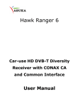
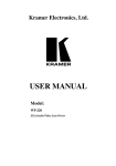
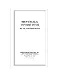
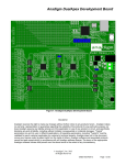
RXC-2000 USB / RS-232 Receiver Decoder Controller Hardware Manual Genave / NRC, Inc. 24234 Chesley Trail Hampton, MN 55031 651-460-6616 Telephone 651-460-6686 Fax www.genave.com [email protected] Copyright 2009. Genave / NRC, Inc. Tech. Publication No. 9000-0000-009 Rev 03 RXC-2000 Receiver Decoder Controller Warning If incorrectly used, this equipment can cause severe injury. Those who use and maintain the equipment should be trained in it's proper use, warned of it's dangers, and should read the manuals before attempting to set up, operate, adjust or service the equipment. Keep this manual for future reference. Important Safety Information System Planning Proper planning is the cornerstone to an effective warning system. The Federal Emergency Management Agency (FEMA) publishes the “Outdoor Warning Guide” CPG 1-17, which should be used in planning your system. In addition, you should recognize and understand the following items: •Outdoor warnings sirens and equipment are not intended to be heard indoors. Conversely indoor devices are not intended to cover outdoor environments. All devices have specific purposes and distances that they can be considered effective. Proper placement and selection of the correct equipment is necessary to cover a desired area. Refer to the FEMA guide for placement guidelines. •Training is necessary to insure those responsible can correctly activate the system. It is also necessary that everyone understand the purpose of the warning system and the protective actions they need to take when the system is activated. Periodic tests can serve to accomplish the training for the operators, in addition to demonstrating the various signals to the public. •All warning systems must have contingency plans in case equipment problems or operator errors interfere with its performance. Just as with the primary warning system, the contingency plans should be periodically tested to make sure those responsible know how to implement them and the necessary response from the public is achieved. 2009,Genave/NRC, Inc 9000-0000-009 Rev 3 Page 2 of 23 RXC-2000 Receiver Decoder Controller Important Safety Information Installation & Service Precautions •Electrocution, severe personal injury and damage to equipment can occur during installation or servicing this equipment. All electrical work should be performed by, or under the supervision of an experienced electrician and in accordance with all applicable electrical, fire, building and safety codes. •This equipment can start at any time from local controls, automatic timers, radio remote, commands from a computer and many other sources. The sound output can cause hearing damage, while other attached equipment can cause personal injury when they engage. Whenever working in or around the equipment you must assume it could activate at any moment, and take appropriate precautions to protect yourself and others. You should completely disable the equipment before working on or in close proximity to any part of it. •You must test the system and equipment to insure it is operating correctly after the installation, as well as after any work has been performed. System Operation •Training is necessary to insure those responsible can correctly activate the system. It is also necessary that everyone understand the purpose of the siren and the protective actions they need to take when the system is activated. Periodic tests can serve to accomplish the training for the operators, in addition to demonstrating the various signals to the public. •You must carefully read and completely understand all the information about the system including its abilities and its limitations. Since no warning system is infallible, you must have contingency plans for warning, in the event the primary systems do not perform as expected, for any reason. 2009,Genave/NRC, Inc 9000-0000-009 Rev 3 Page 3 of 23 RXC-2000 Receiver Decoder Controller ©2009, Genave/NRC, Inc. RXC-2000 Hardware Phone 651-460-6616 Fax 651-460-6686 PRINTED IN USA The contents of this manual are the property of Genave/NRC, Inc. and are copyrighted. Any reproduction in whole or in part is strictly prohibited. For additional copies of this manual or software, please contact Genave/NRC, Inc. Warranty: Genave/NRC, Inc. products are warranted to be free from defects in material and workmanship for a period of ONE (1) year from the date of shipment. Genave, during this period, will repair or replace any parts, which upon our examination appear to be defective in materials or workmanship. This warranty does not apply to defects, malfunctions or breakage due to improper installation, servicing, handling or use thereof, nor to units that have been damaged by lightening or other “Acts of God”, excess current, reversed supply connection, nor to units that have had their serial numbers altered or removed. Equipment damaged in Acts of War, abuse, misuse, tampering, submersion or willful destruction will also void this warranty. Prior to returning equipment for warranty repair, contact the Genave Customer Service Department for an RMA number. They can be reached by using the telephone number or fax number listed above. Genave/NRC, Inc. (Genave) and its licensers offer this warranty in lieu of any and all other guarantees or warranties, either express or implied, including without limitation the implied warranties of merchantability and fitness for a particular purpose, regarding hardware or software. Genave and its licensors do not warrant, guarantee or make any representations regarding the use or the results of the use of the software or hardware in terms of its correctness, accuracy, reliability, most recent or otherwise. You assume the entire risk as to the results and performance. The exclusion of implied warranties is not permitted by some jurisdictions. The above exclusion may not apply to you. In no event will Genave, its licensors, directors, officers, employees or agents (collectively Genave’s licensor) be liable to you for any consequential, incidental or indirect damages (including damages for loss of business profits, business interruption, loss of business information, and the like) arising out of the use or inability to use the software or hardware even if the Genave and/or its licensor has been advised of the possibility of such damages. Because some jurisdictions do not allow the exclusion or limitation of liability for consequential or incidental damages, the above limitations may not apply to you. Genave and its licensors liability to you for actual damages from any cause whatsoever, and regardless of the form of the action (whether in contract, tort, (including negligence), product liability or otherwise), are expressly excluded. Genave reserves the right to make changes in specifications at anytime and without notice. The information furnished by Genave is believed to be accurate and reliable, however, no responsibility is assumed by Genave for its use, nor infringements of patents or other rights of third parties resulting from its use. No license is granted under any patents or patent rights of Genave/NRC, Inc., its licensors or suppliers. Life Support Policy: Genave/NRC, Inc. products are not authorized for use as critical components in life support devices or systems without the express written approval of the president of Genave/NRC, Inc. As used herein: 1) Life support devices or systems are devices or systems which, (a) are intended for surgical implants into the body, or (b) support or sustain life, or whose failure to perform, when properly used in accordance with instructions, can reasonably be expected to result in a significant injury to the user. 2) Critical component is any component of a life support device or system whose failure to perform can be reasonably expected to cause the failure of the life support device or system, or to affect its safety or effectiveness. CSP, Communications Signal Processor, Genave Operating System, GOS, CSP-105, CSP-107, CSP-108, CSP-120, RXC-2000 and RXCPro are Trademarks of Genave/NRC, Inc. The Genave name and logo are Registered trademarks of Genave/NRC, Inc. TouchTone is a Registered trademark of American Telephone and Telegraph. Other names used in this manual are trademarks of their respective companies. 2009,Genave/NRC, Inc 9000-0000-009 Rev 3 Page 4 of 23 RXC-2000 Receiver Decoder Controller Table of Contents GENERAL SPECIFICATIONS............................................................................................7 OVERVIEW.................................................................................................................8 GENERAL..................................................................................................................8 PROGRAMMING...........................................................................................................8 INSTALLATION & THEORY OF OPERATION..........................................................................9 ENCLOSURE...............................................................................................................9 POWER CONNECTION ................................................................................................10 40 WATT POWER SUPPLY FUSING..................................................................................10 DC-DC CONVERTER FUSING......................................................................................11 BATTERY BACKUP.....................................................................................................11 SOLAR OPTION........................................................................................................11 MOTHERBOARD........................................................................................................12 RS-232 PORT........................................................................................................13 USB PORT.............................................................................................................13 ANALOG PORT.........................................................................................................13 FACTORY PORT........................................................................................................13 LCD PORT.............................................................................................................14 CTCSS/DCS........................................................................................................14 SQUELCH................................................................................................................14 TRANSCEIVER INTERFACE PORT....................................................................................15 14 PIN CONNECTOR PINOUT.........................................................................................15 RADIO POWER..........................................................................................................15 PTT DISABLE..........................................................................................................15 2009,Genave/NRC, Inc 9000-0000-009 Rev 3 Page 5 of 23 RXC-2000 Receiver Decoder Controller AUDIO ADJUST.........................................................................................................16 LED STATUS INDICATORS............................................................................................16 CPU BUSY ...........................................................................................................16 CARRIER RX............................................................................................................16 PTT TX.................................................................................................................16 AUD LVL................................................................................................................17 HEARTBEAT.............................................................................................................17 INPUT LEDS...........................................................................................................17 RELAY LEDS..........................................................................................................17 POWER CONNECTORS................................................................................................18 POWER IN...............................................................................................................18 FUSE.....................................................................................................................18 AUX POWER OUT.....................................................................................................18 SPEAKER................................................................................................................18 EXTERNAL SPEAKER PORT...........................................................................................18 SPEAKER DISABLE.....................................................................................................18 OPERATOR SWITCHES................................................................................................19 EXTERNAL INPUTS.....................................................................................................19 ROTARY SWITCH.......................................................................................................19 RELAY OUTPUTS.......................................................................................................20 AUX OUTPUTS.........................................................................................................20 TROUBLESHOOTING GUIDE..........................................................................................21 TONE AND SIGNAL DIAGRAMS......................................................................................23 2009,Genave/NRC, Inc 9000-0000-009 Rev 3 Page 6 of 23 RXC-2000 Receiver Decoder Controller General Specifications General VSUPPLY: ISUPPLY: Weight: Enclosure Size: Enclosure Rating: Power Connector: Temperature: Run Temperature: LCD 90 to 264 VAC, 47 to 63 Hz 1 Amps Maximum 16 lbs. 11.73 in x 11.73 in x 7.25 in NEMA 4X, Polycarbonate 3 Terminals, #6 screw -30 o to +80o C -10 o to +50 o C Inputs Number: 8, Logic level active low, Vin: Debounce: tSCAN: Internal pull-up, 5vdc max 150 msec < 2 msec Relay Outputs Number: V max: I max: Type: Up to 5 230 vac 7 amps 1 Form C LCD Width: Lines: Font: 1 to 16 char. 1 5x7 RF Transceiver Model: Freq Range: Specs: Communication Format Software 2009,Genave/NRC, Inc DTMF Decode MarkMIN: SpaceMIN: Sensitivity: TwistMAX: Interword: Length: 18 msec 18 msec 200 mv p-p, min 3 Vp-p, max +/- 8 dB 0 to 25.5 sec 36 char. max Tone Decode (optional) Accuracy: Selectivity, adj.: Range: S/N Ratio: DetectMI:N DetectMAX: IntertoneMAX: > 0.2% 0 to 4000 Hz 210 – 4000 Hz 0 dB or better 400 msec 25.5 seconds 300 msec Maxon SD-161/171/164/174 148 MHz to 174MHz 450 MHz to 490MHz See Maxon manual for more details Serial (RS232) USB 2.0 Use Genave Comstar software 9000-0000-009 Rev 3 Page 7 of 23 RXC-2000 Receiver Decoder Controller Overview Fig. 1 General The RXC-2000 is a transceiver/controller unit. The unit is equipped with a transceiver, signal decoder & encoder, programmable logic controller, Power supply, up to 5 relay outputs, optional LCD screen, board mounted activation switches, USB and/or RS-232 computer interfaces, all contained in a NEMA 4 weatherproof enclosure. The RXC-2000 is designed to receive DTMF or sequential tone signals (with optional decoder board) sent via radio from a control site and activate any combination of its relays. In addition, the RXC-2000 has the ability to generate tones and DTMF signals under its own program or external computer control. This allows the RXC-2000 to act as an encoder, tone repeater, and transponder. Since the RXC-2000 is programmable, it is not dependent upon any manufacturers particular tone code scheme. It can of course detect and generate Motorola, GE, Bramco, RCA and many other standard codes. But it can just as easily be programmed to use custom tone codes already in use, or to develop your own code schemes for a particular application. Programming Programming of the RXC-2000 is accomplished by using a personal computer, and the Comstar G software from Genave©. Programs for your particular application are written with Comstar G and then downloaded to the RXC-2000 via a USB or serial connection. After downloading, the USB or serial connection is removed and the RXC-2000 functions on its own. Please refer to the serial port section of the “Installation and Theory of Operation” section of this manual for additional information about programming. 2009,Genave/NRC, Inc 9000-0000-009 Rev 3 Page 8 of 23 RXC-2000 Receiver Decoder Controller Installation & Theory of Operation Enclosure The enclosure is made of polycarbonate and has a NEMA 4X rating when shipped from the factory.Four mounting inserts are provided on the back of the enclosure for mounting the box to a wall. The inserts are threaded for metric M5 bolts. Mounting feet are available for the enclosure (Genave P/N 7050-0000-019). The feet allow front-on mounting of the enclosure to a wall and can be mounted vertically, 45 degrees, or horizontally. If you are mounting the equipment to a pole it is important to keep the enclosure flat and not allow the box to twist. The door gasket will not completely seal if there is a twist to the box. If you need design assistance please contact Genave©. We have several options available for pole mounting. When making connections to the enclosure, do not drill through the top or sides of the box. Make all connections through the bottom of the enclosure to maintain at least a NEMA 3R rating. Fig. 2 The internal equipment is mounted to a metal backplane. The backplane is secured to the enclosure with screws that are specifically designed for plastics. Do not use any other type of screw to secure the backplane to the enclosure, it will damage the standoff. Fig. 3 2009,Genave/NRC, Inc 9000-0000-009 Rev 3 Page 9 of 23 RXC-2000 Receiver Decoder Controller Power Connection The RXC-2000 requires 90 to 250 volts AC power to operate. The unit is supplied with a 3 position barrier terminal block. The terminal screw size is #6 screw and will accept a forked terminal with a maximum width of .320”. Terminal #3 is grounded to the backplane. This terminal should be bonded/grounded to earth ground. Fig. 4 AC Connections: 110 Volt : 220 Volt: Connect Hot wire to “Line 1” Connect Neutral wire to “Line 2” Connect Earth Ground wire to “GND” Connect Line 1 to “Line 1” Connect Line 2 to “Line 2” Connect Earth Ground wire to “GND” 40 Watt power supply fusing When equipped with a 40 Watt switching supply, the RXC-2000 power supply is fused for 2 amps. Replace the fuse with a 2 Amp, 250 Volt fuse , Wickmann (Littlefuse) #372 ONLY! The fuse is located on the power supply. REMOVE ALL POWER BEFORE REPLACING THE FUSE!! The fuse terminals are connected directly to the terminal block and will be electrified unless power is removed. If the power cannot be disconnected at the terminal block, disconnect the AC input header on the power supply. Remove the power supply and replace the fuse. Fig. 5 2009,Genave/NRC, Inc 9000-0000-009 Rev 3 Page 10 of 23 RXC-2000 Receiver Decoder Controller DC-DC Converter Fusing When equipped with a DC-DC Isolation supply, the RXC-2000 power supply is fused for 2 amps. Replace the fuse with a 2 Amp 5mm x 20mm 250 Volt fuse ONLY! To replace the fuse, pull the fuse holder cap, twist the fuse out of the cap, twist in a new fuse that is centered on the cap and replace the cap in the holder. Fig. 6 Battery Backup The RXC-2000 can be ordered with an optional sealed lead battery for backup power. The battery is continuously charged from a 15 volt power supply through a blocking diode. The battery voltage is maintained at 14.3VDC. If the RXC-2000 is taken out of service or without power for more than three days, disconnect the battery to prevent excessive discharge. The battery has a gel electrolyte and cannot leak. Replace the battery only with the same type and size. DO NOT use wet cell batteries as a replacement. Solar Option The RXC-2000 can be ordered with an optional solar charger. The charger is a stand alone unit that contains 2 gel batteries. These batteries are connected in parallel with the battery in the RXC-2000. The solar option allows the RXC-2000 to operate up to 5 days without sunlight. 2009,Genave/NRC, Inc 9000-0000-009 Rev 3 Page 11 of 23 RXC-2000 Receiver Decoder Controller Motherboard 2009,Genave/NRC, Inc 9000-0000-009 Rev 3 Page 12 of 23 RXC-2000 Receiver Decoder Controller RS-232 Port The serial port communicates via RS-232 signal levels of +/- 25V. Communication speed is 19,200. Flow controls are 8,1,N Fig. 7 USB port The USB port is a USB 2.0 compatible port. The connector is a Type B. J13 is used when a bulkhead mount USB is required. The power for the USB port is supplied by the computer's USB port only. Fig. 9 Fig. 8 Analog Port The analog port has not been implemented. Please consult Genave© for information. Factory Port The factory port is for Genave© use only. There is no end user functionality. 2009,Genave/NRC, Inc 9000-0000-009 Rev 3 Page 13 of 23 RXC-2000 Receiver Decoder Controller LCD Port The LCD port interfaces to the user's LCD module. The port provides all of the required signals, contrast drive and power for a 1 x 16 module. Fig. 9 CTCSS/DCS/DPL The CTCSS/DCS/DPL jumper enables and disables the sub-audible tone/ privateline function of the Maxon radio. When shorted with a jumper, the CTCSS/DCS/DPL is disabled. When open, the CTCSS/DCS/DPL is enabled. The CTCSS/DCS/DPL is changed via reprogramming of the transceiver. Fig. 12 Squelch The squelch setting is not accessible to the general customer. To adjust the squelch setting, a copy of the Comstar G software and an RF service monitor are required. Please contact Genave to adjust the squelch setting. 2009,Genave/NRC, Inc 9000-0000-009 Rev 3 Page 14 of 23 RXC-2000 Receiver Decoder Controller Transceiver Interface Port Communication and control with the RXC-2000's transceiver are all carried out through this port. This port has been optimized for communication with Maxon SD series radios. However, the RXC-2000 can be connected to any transceiver. 14 pin connector pinout: 1)Not connected 2)Not connected 3)GND 4)+12 Vdc 200mA max 5)Speaker audio from radio 6)GND 7)Not connected 8)/PTT output (300mA max sink) 9)Not connected 10)Discriminator audio (unfiltered) 11)Busy, /CD input (active low) 12)TX audio output 13)Serial data from radio 14)Serial data to radio Fig. 13 Radio power The radio power connector should be used for supply to Maxon radios only. It is turned on and off by the processor and it may not work well on other radios. Please consult Genave© if you would like to use the radio power connector for a different radio. Genave© can modify the firmware to fit your needs. Fig. 14 PTT disable Jumper J29 is used to disable the transceiver's PTT line. This is used to prevent the transceiver from locking up any reason. for Disable Enable Fig. 15 2009,Genave/NRC, Inc 9000-0000-009 Rev 3 Page 15 of 23 RXC-2000 Receiver Decoder Controller Audio Adjust The TX audio pot is a 10k pot driven from a high impedance amplifier. The audio from the TX pot is AC coupled to the Transceiver Interface Port pin 12. Adjust this pot for 3.0 to 3.5 kc deviation from the transceiver. The Rx audio pot is a 10k pot. Audio from the Transceiver Interface Port pin 10 is supplied directly to the high side of the pot. This pot should be adjusted to provide 100mV to 200mV of audio on the wiper when receiving 3.0 kc deviation of 1000 Hz. This pot is not placed on RXC-2000s that use the Maxon radios. Instead, resistors R77 and R78 drop the audio to the correct level. Fig. 16 Fig. 17 LED status indicators These LEDs provide visual indication about the operation of the RXC-2000. CPU Busy: Red The CPU Busy indicator displays when the microprocessor is working on a function. Fig. 18 Carrier Rx: Yellow The Carrier Rx indicator is lit whenever the /CD pin 11 of the Transceiver Interface Port goes low. This is indicative of activity on the channel. PTT Tx: Green The PTT Tx indicator is lit whenever the microprocessor has turned on the PTT transistor and pulled the PTT line pin 8 of the Transceiver Interface Port low. 2009,Genave/NRC, Inc 9000-0000-009 Rev 3 Page 16 of 23 RXC-2000 Receiver Decoder Controller Aud Lvl: This function has not yet been implemented. Heartbeat: Red The heartbeat LED shows if the microprocessor is running by flashing. Fig. 19 Input LEDs: Red The input LEDs are lit when one of the input lines goes low from either a switch pressed by an operator or through the Aux connector. Input Fig. 20 Relay LEDs: Red The relay LEDs are lit whenever an associated relay is active. Fig. 21 2009,Genave/NRC, Inc 9000-0000-009 Rev 3 Page 17 of 23 RXC-2000 Receiver Decoder Controller Power Connectors Power In Power for the RXC-2000 is supplied through J4. Fuse The fuse is a finger-safe fuse holder. Replace the fuse with a 5mm x 20mm 2A, 250V fuse only. Fig. 22 Aux Power Out The Aux Power connectors are designed to supply power to equipment attached to the RXC-2000. The cumulative amount of current supplied through the connectors is 800 mA at 12VDC. There are no fuses in line with these connectors to protect the board. Do not input power through these connectors. Fig. 23 Speaker The pcb mounted speaker provides audio from the transceiver for trouble shooting. External Speaker Port Fig. 24 The external speaker port is connected directly across the speaker. This provides a connection point for the end user to pull audio from the board Speaker Disable The speaker can be disabled by moving the jumper from On to Off. Fig. 25 2009,Genave/NRC, Inc 9000-0000-009 Rev 3 Page 18 of 23 RXC-2000 Receiver Decoder Controller Operator Switches The RXC-2000 provides 8 operator switches. The function of each switch is determined in the software. The switches are sealed for moisture and have an activation force of 160 grams. The white area next to each switch is for the end user to write the function of each switch. External Inputs Each of the switch inputs can be remotely activated by pulling the associated input on the Aux Input header to ground through a dry contact closure. Caution: There is no protection on this header. You can kill the processor if the voltage exceeds 5VDC. Fig. 26 Rotary Switch The Rotary switch is provided to allow field selection of predetermined settings in the user software. The settings could be unit #, Function #, speed, etc. Fig. 27 The switch has 16 positions (Hexadecimal). The table correlates each of the settings to the decimal equivalent and also the DTMF equivalent. 2009,Genave/NRC, Inc 9000-0000-009 Rev 3 Page 19 of 23 RXC-2000 Receiver Decoder Controller Relay Outputs The RXC-2000 provides up to 5 relays. Each relay has the ability to carry 7 Amps of current at 230VAC. Each of the 5 relays is a 1 Form C SPDT relay and each relay has an associated action LED directly above it that indicates when the relay is active. Aux Outputs The auxiliary output connector is tied to each of the transistors that drive the output relays. Each of these lines can sink a maximum of 300mA. The maximum voltage to sink is 12 Vdc Fig. 28 Fig. 29 2009,Genave/NRC, Inc 9000-0000-009 Rev 3 Page 20 of 23 RXC-2000 Receiver Decoder Controller RXC-2000 Trouble Shooting Guide Problem Symptoms The RXC-2000 has No heartbeat no power. No characters on the LED No action from the switches The RXC-2000 does not decode Unit operates from switches but not tones or DTMF The “CPU busy” light flashes after receiving tones or DTMF codes, but does not function. Possible Causes Actions Fuse is blown Check the fuse on the motherboard (F203). This is a 5mm x 20mm 2 Amp glass fuse. Fig. 22 Power supply failure The green light on the power supply should be on when the power supply is running. If it is not on, make sure that AC voltage is being sent to the power supply. If the unit has AC power but is not operating, there is a small fuse on the power supply. Regulator failure Check the output of the regulator U7 just above the aux power Connectors. There should be +12Vdc in and +5Vdc out. Antenna Connection Check the antenna connection. It may need an outside antenna if the transmitter signal is too weak. Engage the speaker (jumper 1 “On”). Listen for tones or DTMF codes. Fig. 24 Receiving an incorrect code or sub-audible code Check the J20 jumper. If the unit has been programmed for a DCS/CTCSS/DPL code, it may be receiving a low or incorrect code. Shorting J20 (turns off sub-audible tone decoder) and then try sending the unit the tones or DTMF codes again. Radio connection Check radio connections (J2 and J3) The unit may be incorrectly programmed and waiting for a different set of tones or DTMF codes. Check the program. The tones could be the incorrect frequency, too short in duration or too long of an inter-tone gap between the tones. Fig. 30 Use an oscilloscope and look at the signal at the wiper of potentiometer R75. The signal should be a sinusoid and not be distorted, clipped or folded back. The signal should be between 100mV and 200mV peak to peak at the wiper. Fig. 31 Troubleshooting, cont. 2009,Genave/NRC, Inc 9000-0000-009 Rev 3 Page 21 of 23 RXC-2000 Problem Receiver Decoder Controller Symptoms Possible Causes Actions Signals are folded back or clipped Although the RXC-2000 can listen for tones and DTMF codes in poor quality audio signals, the signals are decoded easily if they are not malformed. If the signals are folded back or clipped, they create harmonics in the signal which can keep the RXC-2000 from understanding the fundamental signal if the harmonics become too large. (Fig 31.) Squelch setting is too tight If the squelch setting is too tight, the RXC 2000's receiver will never open and allow the signal to go to the decoder. The RXC-2000 Unit starts by itself activates randomly Unit has received an activation code from a very remote source due to signal “skip”. Program the RXC-2000 and the activation source with a sub-audible tone. Frequency counter or DTMF grabber must be shut off for proper operation The RXC-2000 Distracting noise produces unsquelched audio through the speaker Squelch setting is not tight enough Tighten the squelch setting. The squelch setting will need to be adjusted. Squelch requires Comstar G program and RF communication service meter. 2009,Genave/NRC, Inc 9000-0000-009 Rev 3 Page 22 of 23 RXC-2000 Receiver Decoder Controller Fig. 30 Fig. 31 2009,Genave/NRC, Inc 9000-0000-009 Rev 3 Page 23 of 23