1
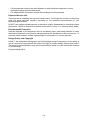
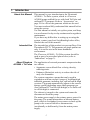
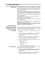
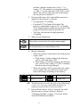
FLOWTRON ACS800
+TRI PULSE
INSTRUCTIONS FOR USE
0086
...with people in mind
Contents
General Safety . . . . . . . . . . . . . . . . . . . . . . . . . . . . . . . . . . . . . . . . . . . . . . . . . . . . . . . iii
Introduction . . . . . . . . . . . . . . . . . . . . . . . . . . . . . . . . . . . . . . . . . . . . . . . . . . . . . . . . .
About this Manual . . . . . . . . . . . . . . . . . . . . . . . . . . . . . . . . . . . . . . . . . . . . . . . . . . .
Intended Use . . . . . . . . . . . . . . . . . . . . . . . . . . . . . . . . . . . . . . . . . . . . . . . . . . . . . . .
About Flowtron ACS800 + Tri Pulse . . . . . . . . . . . . . . . . . . . . . . . . . . . . . . . . . . . . .
Pump: Front View . . . . . . . . . . . . . . . . . . . . . . . . . . . . . . . . . . . . . . . . . . . . . . . . . . .
Pump: Rear View . . . . . . . . . . . . . . . . . . . . . . . . . . . . . . . . . . . . . . . . . . . . . . . . . . .
1
1
1
1
2
2
Clinical Applications . . . . . . . . . . . . . . . . . . . . . . . . . . . . . . . . . . . . . . . . . . . . . . . . . .
Indications . . . . . . . . . . . . . . . . . . . . . . . . . . . . . . . . . . . . . . . . . . . . . . . . . . . . . . . . .
Contraindications . . . . . . . . . . . . . . . . . . . . . . . . . . . . . . . . . . . . . . . . . . . . . . . . . . .
Cautions . . . . . . . . . . . . . . . . . . . . . . . . . . . . . . . . . . . . . . . . . . . . . . . . . . . . . . . . . .
Guidelines and Recommendations . . . . . . . . . . . . . . . . . . . . . . . . . . . . . . . . . . . . . .
3
3
3
4
5
Controls, Alarms and Indicators . . . . . . . . . . . . . . . . . . . . . . . . . . . . . . . . . . . . . . . . 6
Control Panel With Typical LCD Screen View in Run Mode . . . . . . . . . . . . . . . . . . . 6
LED Indicators on the Front Case . . . . . . . . . . . . . . . . . . . . . . . . . . . . . . . . . . . . . . . 9
Operation . . . . . . . . . . . . . . . . . . . . . . . . . . . . . . . . . . . . . . . . . . . . . . . . . . . . . . . . . .
General . . . . . . . . . . . . . . . . . . . . . . . . . . . . . . . . . . . . . . . . . . . . . . . . . . . . . . . . . .
Start Up . . . . . . . . . . . . . . . . . . . . . . . . . . . . . . . . . . . . . . . . . . . . . . . . . . . . . . . . . .
Standby Screens . . . . . . . . . . . . . . . . . . . . . . . . . . . . . . . . . . . . . . . . . . . . . . . . . . .
Starting Therapy . . . . . . . . . . . . . . . . . . . . . . . . . . . . . . . . . . . . . . . . . . . . . . . . . . .
Stopping Therapy . . . . . . . . . . . . . . . . . . . . . . . . . . . . . . . . . . . . . . . . . . . . . . . . . .
Switching Off the Pump . . . . . . . . . . . . . . . . . . . . . . . . . . . . . . . . . . . . . . . . . . . . .
Alarms . . . . . . . . . . . . . . . . . . . . . . . . . . . . . . . . . . . . . . . . . . . . . . . . . . . . . . . . . . .
Changing Options . . . . . . . . . . . . . . . . . . . . . . . . . . . . . . . . . . . . . . . . . . . . . . . . . .
Settings Adjustment . . . . . . . . . . . . . . . . . . . . . . . . . . . . . . . . . . . . . . . . . . . . . . . .
10
10
10
11
13
15
16
16
16
20
Decontamination . . . . . . . . . . . . . . . . . . . . . . . . . . . . . . . . . . . . . . . . . . . . . . . . . . . . 21
Routine Maintenance . . . . . . . . . . . . . . . . . . . . . . . . . . . . . . . . . . . . . . . . . . . . . . . .
Flowtron ACS800 + Tri Pulse System . . . . . . . . . . . . . . . . . . . . . . . . . . . . . . . . . . .
Pump . . . . . . . . . . . . . . . . . . . . . . . . . . . . . . . . . . . . . . . . . . . . . . . . . . . . . . . . . . . .
Serial Labels . . . . . . . . . . . . . . . . . . . . . . . . . . . . . . . . . . . . . . . . . . . . . . . . . . . . . .
22
22
22
22
Troubleshooting . . . . . . . . . . . . . . . . . . . . . . . . . . . . . . . . . . . . . . . . . . . . . . . . . . . . 23
Accessories . . . . . . . . . . . . . . . . . . . . . . . . . . . . . . . . . . . . . . . . . . . . . . . . . . . . . . . . 29
Technical Specification . . . . . . . . . . . . . . . . . . . . . . . . . . . . . . . . . . . . . . . . . . . . . . 30
(i)
(ii)
GENERAL SAFETY
Before you connect the system pump to a mains socket, read carefully all the installation
instructions contained within this manual.
The system has been designed to comply with regulatory safety standards including:
• EN60601-1:1990/A13:1996 and IEC 60601-1:1988/A2:1995.
• UL60601-1 and CAN/CSA C22.2 No. 601.1-M90.
• EN60601-1:2006 and IEC 60601-1:2005
• AAMI/ANSI ES60601-1:2006 and CAN/CSA C22.2 No.60601.1(2008)
Safety Warnings
• It is the responsibility of the care giver to ensure that the user can use this product
safely.
• Make sure that the mains power cable and tubeset or air hoses are positioned to
avoid causing a trip or other hazard, and are clear of moving bed mechanisms or
other possible entrapment areas.
• Electrical equipment may be hazardous if misused. There are no user-serviceable
parts inside the pump. The pump's case must only be removed by authorised
technical personnel. No modification of this equipment is allowed.
• The mains power socket/plug must be accessible at all times. To disconnect the
pump completely from the electricity supply, remove the plug from the mains
power socket.
• Disconnect the pump from the mains power socket before cleaning and inspecting.
• Keep the pump away from sources of liquids and do not immerse in water.
• Do not use the pump in the presence of uncontained flammable liquids or gasses.
• Only the pump and garment/insert combination as indicated by ArjoHuntleigh
should be used. The correct function of the product cannot be guaranteed if
incorrect pump and garment combinations are used.
• The Flowtron® ACS800 + Tri Pulse system is NOT intended for use in the Home
Healthcare Environment (e.g. private dwellings or nursing homes).
Caution (applicable to the USA market only)
• US Federal law restricts this device to sale by or on the order of a physician.
Precautions
For your own safety and the safety of the equipment, always take the following precautions:
• Do not expose the system to open flames, such as cigarettes, etc.
• Do not store the system in direct sunlight.
• Do not use phenol-based solutions to clean the system.
• Make sure the system is clean and dry prior to use or storage.
Electromagnetic Compatibility (EMC)
This product complies with the requirements of applicable EMC Standards. Medical electrical
equipment needs special precautions regarding EMC and needs to be installed in accordance
with the following instructions:
• The use of accessories not specified by the manufacturer may result in increased
emissions by, or decreased immunity of, the equipment, affecting its performance.
• Portable and mobile radio frequency (RF) communications equipment (e.g. mobile/cell
phones) can affect medical electrical equipment.
(iii)
• If this equipment needs to be used adjacent to other electrical equipment, normal
operation must be checked before use.
• For detailed EMC information contact ArjoHuntleigh service personnel.
Expected Service Life
The pump has an expected service life of seven years. To maintain the condition of the pump
have the pump serviced regularly according to the schedule recommended by your
ArjoHuntleigh distributor.
Do NOT use unapproved accessories or attempt to modify, disassemble or otherwise misuse
the system. Failure to observe this caution could result in injury, or in extreme cases, death.
Environmental Protection
Incorrect disposal of this equipment and its component parts, particularly batteries or other
electrical components, may produce substances that are hazardous to the environment. To
minimise these hazards, contact ArjoHuntleigh for information on correct disposal.
Design Policy and Copyright
® and ™ are trademarks belonging to the ArjoHuntleigh group of companies. As our policy is
one of continuous improvement, we reserve the right to modify designs without prior notice.
The content of this publication may not be copied either whole or in part without the consent
of ArjoHuntleigh.
© ArjoHuntleigh 2014
(iv)
1. Introduction
About this Manual
This manual is your introduction to the Flowtron®
ACS800 + Tri Pulse system, which is a Flowtron
ACS800 pump enabled for use with both Tri Pulse and
uniform DVT garments. Refer to “Accessories” on
page 29 for a list of the garments which can be used.
You must read and fully understand this manual before
using the system.
Use this manual to initially set up the system, and keep
it as a reference for day-to-day routines and as a guide to
maintenance.
If you have any difficulties in setting-up or using the
system, contact your local ArjoHuntleigh sales office,
listed at the end of this manual.
Intended Use
The intended use of this product is to prevent Deep Vein
Thrombosis (DVT). The garments are single patient use
only. It is not for use in the home healthcare
environment.
The Flowtron ACS800 + Tri Pulse system should be
used as part of a prescribed plan of care (refer to
“Indications” on page 3).
About Flowtron
ACS800 + Tri Pulse
The application of external pneumatic compression has
two effects:
• Augments venous blood flow velocity, thereby
reducing stasis.
• Enhances fibrinolytic activity to reduce the risk of
early clot formation.
The system comprises a pump that can be used in
conjunction with an extensive range of ArjoHuntleigh
inflatable garments, including foot, calf and calf & thigh
versions. The pump automatically adjusts to the correct
therapy profile depending upon which garment type
(foot, uniform DVT calf or calf & thigh, or Tri Pulse calf
or calf & thigh) is connected.
The tubeset is integral to the system and cannot be
disconnected from the pump.
The mains power supply is the primary power source for
the pump. The pump incorporates an internal battery
pack, which is a secondary power source to back up the
pump in the event of failure or disconnection
(accidentally or deliberately) from the mains power
supply.
1
The system is intended for use ONLY in Professional
Healthcare Facilities (e.g. hospitals or physicians’
offices).
A full technical description of the Flowtron ACS800 +
Tri Pulse system can be found in the Service Manual,
part number SER0020, available from your local
ArjoHuntleigh sales office.
Pump: Front View
LCD Screen
and Controls
Integral Carry Handle
Integral
Tubesets
LED Indicator
Tubeset 1
(Blue Button)
Garment
Connectors
Tubeset 2
(Orange Button)
Pump: Rear View
Swing-out
Bed-Hooks
Tubeset 1
Integral
Tubesets
Mains Power Cord
Tubeset 2
2
2. Clinical Applications
Indications
The intended use of the Flowtron ACS800 + Tri Pulse
system is to help prevent Deep Vein Thrombosis (DVT).
The system should be combined with an individualised
monitoring programme.
These systems represent one aspect of a DVT strategy;
if the patient's condition changes the overall therapy
regimen should be reviewed by the prescribing clinician.
The above are guidelines only and should not replace
clinical judgement.
Depending on the garment type used, other clinical
applications are also appropriate.
The FG foot garment, in particular, has a wide range of
clinical applications.
Full details for clinical applications are included in the
packaging of every garment.
The type of garment used on an individual patient
must be specified by a physician.
Contraindications
Uniform DVT Calf/Calf
& Thigh and Tri Pulse
Calf/Calf & Thigh
Garments
Foot Garments
The system, when used with the uniform DVT calf/calf
& thigh and Tri Pulse calf/calf & thigh garments, should
not be used in the following conditions:
1. Severe arteriosclerosis or other ischemic vascular
diseases.
2. Severe congestive cardiac failure or any condition
where an increase of fluid to the heart may be
detrimental.
3. Known or suspected acute deep vein thrombosis,
thrombophlebitis or pulmonary embolism.
4. Any local condition in which the garments would
interfere, including:
• Gangrene
• Recent skin graft
• Dermatitis
• On untreated, infected leg wounds.
The system, when used with the foot garments, should
not be used in the following conditions:
1. Severe congestive cardiac failure or any condition
where an increase of fluid to the heart may be
detrimental.
2. Known or suspected acute deep vein thrombosis,
thrombophlebitis or pulmonary embolism.
3
3. Any local condition in which the garments would
interfere, including:
• Gangrene
• Recent skin graft
• Dermatitis
• On untreated, infected leg wounds
If you are unsure of any contraindications refer to the patient’s physician before
using the device.
Cautions
1. Proper garment application and connection to the
pump is essential.
2. Garments should be positioned in such a way that
there is no potential for sustained pressure points on
the skin and underlying tissues. Lower limb
positioning in relation to the garment and tubing
should also be considered particularly in a patient
that is unconscious, cannot feel or has reduced
sensation and/or ability to move their leg(s).
3. While using the system, the patient's skin should be
inspected frequently and regularly, paying
particular attention to bony prominences such as
the malleolus and heel. It is recommended that
these checks should be performed not less than
every hour if the patient cannot feel or has reduced
sensation and/or ability to move their leg(s); in all
other patients, perform these checks not less than
every 6 hours.
4. Clinical judgement is required to determine if the
patient's skin condition requires additional
protective measures, or if the therapy should be
discontinued and an alternative modality used.
5. Garments should be removed immediately if the
patient experiences tingling, numbness, or pain, and
the physician notified.
6. When used for DVT prevention, continuous
external pneumatic compression is recommended
until the patient is fully ambulatory. Uninterrupted
use of the system is encouraged.
7. The system should be USED WITH CAUTION
on patients with:
• Insensitive extremities.
• Diabetes.
• Impaired circulation.
• Fragile or impaired skin.
4
These are guidelines only and should not replace
clinical judgement and experience.
Guidelines and Recommendations
General • While using the system, the patient’s limbs should be
checked not less than every six hours, and more often
Recommendations
if the patient has known circulatory or skin problems,
or is diabetic.
• Note: Many patients are at risk for pressure ulcers on
the heel. Use of the foot garments does not negate the
necessity for heel protection and proper skin care.
• Clinical judgment should be used to determine if the
patient’s skin condition requires additional measures,
or if the treatment should be discontinued and
alternative modalities used.
• ArjoHuntleigh does not recommend the use of
compression stockings with its system. If these are
ordered by the physician, the clinician should ensure
that the compression stockings are properly
measured, applied and worn by the patient. Any
compression stocking used should be routinely
checked to ensure continued proper fit and
application, in addition to assessing the condition of
the skin.
• Where appropriate, patients should be instructed in
the proper use of the system, the purpose of therapy
and that any problems should be reported to the
nursing staff.
DVT Prophylaxis • The system should be applied to the patient preoperatively, prior to the induction of anaesthesia.
• The system should be used continuously for no less
than 72 hours post-operatively or until the patient
becomes fully ambulatory.
• If the garment cannot be applied to the operative
limb during surgery, it may be applied to the limb
once the patient reaches the recovery unit.
• In the non-surgical patient, the system should be
initiated immediately the risk of DVT formation is
identified.
5
3. Controls, Alarms and Indicators
Control Panel With Typical LCD Screen View in Run Mode
Garment Type and Therapy Indicator
(the possible garment types are detailed in “LCD Screen” section below)
Mains/Power Indicator
Battery Indicator
LED Indicator
Pressure
Indicator
On/Off Button
Stop
2h
LCD Screen
Patient
Hours Meter
Start/Stop
Therapy
“Down” Select Button
On/Off Button
and LED Indicator
Start/Stop Button
“Up” Select Button
Press the On/Off button to power up the pump from its
unpowered state and put it into Standby (refer to
“Standby Screens” on page 11).
Connecting the pump to the mains power supply will
automatically power up the pump from its
unpowered state and put it into Standby, without
having to press the On/Off button.
Make sure the system has been arranged so that the
power cable and garment hoses do not pose a trip or
strangulation hazard.
The adjacent LED indicator shows the pump status:
LED Colour
Mains Power
Pump Status
Extinguished
Disconnected
Off
Amber
Connected
Off
Amber
Connected or disconnected
Standby
Green
Connected or disconnected
Run
To switch off the pump, press and hold the On/Off
button for approximately 2 seconds until the LCD screen
goes blank, and then release.
If you switch off the pump and then press the On/Off
button to power it back up:
6
Start/Stop Button
“Up” and “Down”
Select Buttons
LCD Screen
• If the mains power is disconnected, the pump runs
the diagnostic tests and then goes into Standby.
• If the mains power remains connected, the pump
goes into Standby and does not run diagnostic tests.
This has the following functions depending on the text
or icon displayed above the button:
• To start or stop therapy.
• To confirm the option selected in the Options menu.
When the pump is in Standby, press the Start/Stop
button to put the pump into the Run mode and start
therapy; the LED indicator adjacent to the On/Off button
will change to green and the LEDs on the front case will
be illuminated green.
To stop the therapy and put the pump into Standby, press
and hold the Start/Stop button for approximately 2
seconds until the Standby screen is displayed and then
release the button. The LED indicator adjacent to the
On/Off button changes to amber and the LEDs on the
front case are extinguished.
These have the following functions depending on the
text or icon displayed above the buttons:
• To select the Options menu.
• To move up and down the Options menu.
• To mute certain audible alarm conditions.
This displays the pump operating mode and status:
1. Foot, uniform DVT calf (or calf & thigh) or
Tri Pulse calf (or calf & thigh) therapy indications.
These show what garment type is connected to each
tubeset and when each garment is being inflated:
Uniform
DVT Calf or
Calf & Thigh
Garment
Foot
Garment
Tri Pulse
Calf or Calf
& Thigh
Garment
• All therapy indications are initially shown as
grey to indicate they are deflated.
• A therapy indication changes to black to show it
is inflating.
• The therapy indication reverts to grey when it
starts to deflate.
• The garment connector on the end of each
tubeset has a push button which is colour-coded
7
and has a number marked on it: blue “1” or
orange “2”. The numbers corresponds with the
“1” and “2” on the right side of the LCD screen.
Where the tubesets enter the side of the pump,
the top tubeset is marked “1”.
2. Pressure indication: this is the inflation pressure
applied to the garment, as follows:
• Foot garment: 130 mmHg.
• Uniform DVT calf and calf & thigh. The
pressure is adjustable between 35 - 65 mmHg.
To be adjusted only by authorised personnel. The
pump will default to the last pressure set.
• Tri Pulse calf and calf & thigh garments:
45 mmHg.
3. Mains power indications:
The pump is connected to the mains power supply.
The pump is not connected to the mains power supply,
but is powered by the internal battery only.
4. Battery indication:
• When the pump is connected to the mains power
supply, then:
•• If the battery is fully charged, the indicator
will be static and show “full”.
•• If the battery is not fully charged, the indicator
will “scroll” from “empty” to “full” to indicate
that the pump is being charged.
• When the pump is NOT connected to the mains
power supply, then the indicator is static and
shows the charge remaining in the battery:
Battery Empty
Battery 1/3 Full
Battery 2/3 Full
Battery Full
The battery has a service life of 5 years (600 charge
cycles). It is not user replaceable and must be
replaced as part of the service procedure.
5. Patient Hours Meter: if this is selected, the total
therapy time is shown (in hours). Refer to
“Changing Options” on page 16 to select and/or
clear the Patient Hours Meter.
8
• This is the pump run time since the Patient Hours
Meter was last cleared.
• The factory default is to NOT show the Patient
Hours Meter on the LCD screen.
6. Warning and alarm indications (refer to
“Troubleshooting” on page 23).
LED Indicators on the
Front Case
There are two sets of LED indicators on the front case of
the pump. Their status is as follows:
LED Colours
Pump Status
Warnings/Alarms
Extinguished
Off or Standby
--
Green (Static)
Run
Red (Flashing)
Run
• No fault detected.
• Warning only detected.
Fault detected with full audible and visual alarm
9
4. Operation
These instructions cover the day-to-day operation of the
system. Other operations, such as maintenance and
repair, should only be carried out by suitably qualified
personnel.
Refer to “Controls, Alarms and Indicators” on page 6 for
a description of the controls, indicators and LCD screen.
If the operation or performance of the pump
changes during use, refer to “Troubleshooting” on
page 23 of this IFU before calling a service
engineer or contacting your local ArjoHuntleigh
sales office.
Start Up To switch on the pump, do one of the following:
• Connect the pump to the mains power supply using
the power cable provided. The pump will power up
automatically and start running a diagnostic test, and
display the following screen:
General
Progress
Bar
• If operating from just the battery (disconnected from
the mains power supply), press the On/Off button.
The pump will power up and start running the
diagnostic test, and display the following screen.
Note the “Checking Battery” text and the “Mains
power not connected” icon at the top of the screen:
Checking Battery
“Mains power not
connected” icon
10
After a few seconds, the following screen is
displayed, showing “Battery OK”:
Battery OK
If the text at the top of the screen says “Low
Battery” then you must connect mains power before
you can start therapy.
• At the end of the diagnostic test, the following screen
is displayed, showing the “Hours Run” at the top, the
software version of the pump at the bottom and
“ACS800 Tri Pulse” below “Flowtron”:
Hours Run: 145
ACS800 Tri Pulse
XX.XXXX-XXX
Standby Screens
“Mains power
connected” icon
The “Hours Run” value displayed on this screen is
for service use only, and is different to the “Patient
Hours Meter” displayed during therapy. Refer to
“Controls, Alarms and Indicators” on page 6 for
the “Patient Hours Meter”.
The “No Garments” Standby screen is then displayed:
Attach garments
Battery
Indication
Options
There are two “leg” icons with no garments attached and
the text “Attach garments” at the top of the screen; this
indicates that no garments are currently connected to
either tubeset.
There is no text above the Start/Stop button until at
least one garment is connected to a tubeset.
Apply the prescribed ArjoHuntleigh garment(s) to the
patient by following the instructions included in the
garment packaging.
11
Garments are for single patient use only. Do not use
the garments on a different patient after treatment.
Connect the garment(s) to the pump by pushing the
garment connector firmly into the pump tubeset
connector until it “clicks”.
The pump LCD screen will show which garments are
connected to each tubeset connector: the garment
connector with the blue push button is “1” and the one
with the orange push button is “2”.
If any pump options (Audio Alarm Volume, Patient
Hours Meter or Language) need to be changed, they
must be changed before the patient therapy is started.
Refer to “Changing Options” on page 16.
The following six screens show typical Standby screens
with different garment configurations:
Start
Start
Options
Foot Garment
Connected to Tubeset 1
Start
Uniform DVT Calf (or Calf & Thigh)
Garment Connected to Tubeset 1
Options
Start
Two Uniform DVT Calf (or Calf &
Thigh) Garments Connected
Start
Options
Options
Foot and Uniform DVT Calf (or
Calf & Thigh) Garments Connected
Start
Options
Options
Foot and Tri Pulse Calf (or Calf & Thigh)
Garments Connected
Tri Pulse Calf (or Calf & Thigh)
Garment Connected to Tubeset 1
12
Starting Therapy
Make sure the garment(s) are fitted correctly to the
patient and the pump.
Make sure any pump options have been changed if
necessary.
If the pump is to be positioned under a bed, make
sure it is placed horizontally (with the bed-hooks
underneath) to prevent damage to the pump.
While the pump is in Standby, the LEDs on the front
case remain extinguished.
Press the button below “Start” to start the therapy. The
LEDs on the front case change to static green.
It is recommended that the following checks are carried
out at the start of, and throughout, the therapy:
• Check the LCD screen icons to confirm that the
correct type of garment(s) have been connected.
• During garment inflation, check the LCD screen to
confirm that there are no fault messages displayed
and that the correct pressure is being supplied. The
supplied inflation pressures for the different
garments are:
• Foot garment: 130 mmHg.
• Uniform DVT calf and calf & thigh garments:
40 mmHg.
• Tri Pulse calf and calf & thigh garments:
45 mmHg.
Initial inflation cycles (up to 10) may not show the
correct inflation pressure. This is to be expected.
• Check that there are no kinks in the pump tubesets.
• Check that the pump tubesets and connectors do not
cause the patient any discomfort.
• Regularly check that the garments remain correctly
fitted to the patient.
The pump will inflate and deflate each garment in turn,
as follows, starting with garment 1:
The following example shows two foot garments
fitted to the pump.
1. Both garments are initially deflated. The garment
pressure is displayed on the left side of the screen.
If the Patient Hours Meter is selected in the
“Options” menu (refer to “Changing Options” on
13
page 16), the total elapsed time (in hours) is shown
in the bottom right of the screen:
Stop
2h
Patient Hours Meter
2. Foot garment 1 is inflated to 130 mmHg, with a
ramp up and hold time of 3 seconds. The foot
garment indicator is black while it is inflated:
Stop
2h
3. The foot garment is deflated to zero. Both garment
indicators are grey:
Stop
2h
4. Foot garment 2 is then inflated to 130 mmHg, with
a ramp up and hold time of 3 seconds. The foot
garment indicator is black while it is inflated:
Stop
14
2h
5. The foot garment is deflated to zero. Both garment
indicators are grey:
Stop
2h
6. This cycle of alternate garment inflations repeats
from step 2 (above) until the therapy is stopped.
If calf (or calf & thigh) garments are attached to the
pump, then each of these garments is inflated to
40 mmHg (uniform DVT) or 45 mmHg (Tri Pulse),
with a ramp up and hold time of 12 seconds.
If a foot garment, uniform DVT calf (or calf & thigh) or
Tri Pulse calf (or calf & thigh) garment are attached to
the pump, then since the inflate and hold times for a foot
garment are shorter than for a calf (or calf & thigh)
garment, there is a modified inflation sequence: the foot
garment is always inflated twice in succession and then
the uniform DVT calf (or calf & thigh) or Tri Pulse calf
(or calf & thigh) garment is inflated, as follows.
The first garment to be inflated is always garment 1.
1. Inflate the foot garment to 130 mmHg.
2. Deflate the foot garment.
3. Repeat the inflation of the foot garment to
130 mmHg.
4. Deflate the foot garment.
5. Inflate the uniform DVT calf (or calf & thigh)
garment to 40 mmHg or the Tri Pulse calf (or calf
& thigh) garment to 45 mmHg.
6. Deflate the uniform DVT calf (or calf & thigh)
garment or Tri Pulse calf (or calf & thigh) garment.
7. This cycle of garment inflations repeats from step 1
(above) until the therapy is stopped.
Stopping Therapy
To stop the therapy and put the pump into Standby, press
and hold the Start/Stop button for approximately 2
seconds until the Standby screen is displayed (refer to
“Standby Screens” on page 11) and then release it.
The LED indicator by the On/Off button changes to
amber and the LEDs on the front case are extinguished.
15
If the pump stays in Standby, then:
1. After 5 minutes the LCD display backlight is
dimmed.
2. After a further 15 minutes (20 minutes total) the
pump automatically switches off.
The LED indicator will remain amber if the pump is
connected to the mains power and extinguished if
the mains power is disconnected.
Switching Off
the Pump
1. Make sure the therapy is stopped and the pump is in
Standby (refer to “Stopping Therapy” on page 15).
2. Press and hold the On/Off button for approximately
2 seconds until the LCD screen goes blank and then
release it.
The LED indicator will remain amber if the pump is
connected to the mains power and extinguished if
the mains power is disconnected.
Alarms
On detection of a fault condition, the pump provides a
visual-only warning followed by an audible and visual
alarm if the fault is not cleared.
1. The visual-only warning is a fault message on the
LCD screen. The LED indications remain
unchanged and there is no audible alarm.
2. If the fault is not cleared then the warning is
replaced by an audible and visual alarm, which
consists of:
• A fault message on the LCD screen.
• The LED indicators on the front of the pump
change to red and start flashing.
• An audible alarm will sound which increases in
pitch and intensity if the alarm is ignored.
The warning and alarm can be cleared by either:
• Checking and rectifying the fault on the system, or
• Pressing the button below “Stop” to put the pump
into Standby.
Refer to Section 7, Page 23 “Troubleshooting” for the
alarms, their possible causes and their remedies.
Changing Options
To change the pump operating options, the pump must
be in Standby. If the pump is in Run mode, press and
hold the button below “Stop” for 2 seconds to put the
pump into Standby.
16
On the Standby screen, press the button below
“Options” and the “Options” menu is displayed:
• The “border” around an item indicates the currently
selected item.
• To select a new menu item, press the buttons below
the “up” and “down” arrows.
• To confirm the new menu item, press the button
below the “tick”.
• To exit and return to the Standby screen, select and
confirm “Exit” on the menu.
1. To change the Audio Alarm Volume setting:
• On the “Options” menu, select and confirm
“Audio Alarm Volume” and the “Audio Alarm
Volume” screen is displayed:
Set Volume High
Set Volume Low
Back
Exit
• The “tick” on the left side of the screen shows
that the alarm is currently set to High Volume.
• Use the “up” and “down” buttons to select the
new volume setting. Press the “tick” button to
confirm the new volume. The “tick” now shows
the new setting.
• To exit and return to the Standby screen, select
and confirm “Exit”.
• To change another option, select and confirm
“Back” and the “Options” menu is displayed.
2. The Patient Hours Meter settings.
When selected, the Patient Hours Meter shows the
total therapy time at the bottom right of the LCD
screen during therapy.
This is the elapsed time since the Patient Hours
Meter was last cleared using these commands.
17
To change the settings:
• On the “Options” menu, select and confirm
“Patient Hours Meter” and the “Patient Hours
Meter” screen is displayed:
Show Patient Hours
Clear Patient Hours
Back
Exit
Hours Run 00001
• A “tick” to the left of “Show Patient Hours”
indicates that the total therapy time is shown in
the bottom right of the LCD screen during
therapy.
• To change this setting, use the “up” and “down”
buttons to make sure the “Show Patient Hours”
option is selected, and then press the “tick”
button to toggle the option on or off.
• The text “Hours Run 00001” indicates the
current value of the Patient Hours Meter.
• To clear the elapsed time showing in the Patient
Hours Meter (for example, when therapy is
started on a new patient), use the “up” and
“down” buttons to select the “Clear Patient
Hours” option.
• Press the “tick” button TWICE to clear the
“Hours Run” to “00000”. The Patient Hours
Meter on the LCD screen will show “0h” during
therapy, if selected.
You must press the “tick” button twice.
• To exit and return to the Standby screen, select
and confirm “Exit”.
• To change another option, select and confirm
“Back” and the “Options” menu is displayed.
18
3. To select a new Language:
• On the “Options” menu, select and confirm
“Language” and the “Language” screen is
displayed:
EN - English
ES - Espanõl
FR - Français
DE - Deutsch
IT - Italiano
• The “tick” on the left side of the screen shows
that the language is currently set to “English”.
• Use the “up” and “down” buttons to select the
new language, e.g. “FR - Français”:
The list of languages depends on the territory, but is
typically:
EN - English
ES - Español
FR - Français
DE - Deutch
IT - Italiano
NL - Nederlands
PT - Português
SV - Svenska
NO - Norsk
DA - Dansk
EN - English
ES - Espanõl
FR - Français
DE - Deutsch
IT - Italiano
• Press the “tick” button to confirm that “French”
has been selected.
• A second confirmation screen is displayed with
just the new language (French) displayed:
FR - Français
Back
Exit
19
• Press the “tick” button to confirm the change of
language to French.
• The screen now displays the “Options” menu in
the new language (French):
Volume alarme audio
Compteur patient
Langue
Sortie
To exit and return to the Standby screen, select and
confirm “Sortie”.
Settings Adjustment
The pump is configured to give the recommended
therapy for each garment type and does not require any
direct setting by the clinician or nurse.
If the physician requires different therapy settings for
uniform DVT calf and calf & thigh garments, then
limited changes can be made to the pump pressure by
accessing a Service screen on the pump. Contact your
local ArjoHuntleigh sales office for details.
The pump pressures for Foot garments and
Tri Pulse calf and calf & thigh garments are fixed
and cannot be changed.
The pressure range and factory default pressure for
the uniform DVT calf and calf & thigh garments are
detailed in the “Technical Specification” on
page 30.
20
5. Decontamination
The following processes are recommended, but should be adapted to comply with the local
or national guidelines (Decontamination of Medical Devices) which may apply within the
Healthcare Facility or the country of use. If you are uncertain, you should seek advice from
your local Infection Control Specialist.
The system should be routinely decontaminated between patients and at regular intervals
while in use; as is good practice for all reusable medical devices.
WARNING
Remove the electrical supply to the pump by disconnecting the mains power
cable from the mains power supply before cleaning.
Protective clothing should always be worn when carrying out decontamination
procedures.
Caution
Do not use Phenol-based solutions or abrasive compounds or pads during the
decontamination process as these will damage the surface coating. Avoid
immersing electrical parts in water during the cleaning process. Do not spray
cleaning solutions directly onto the pump. Do not immerse the tubeset in
water.
To clean
Clean all exposed surfaces and remove any organic debris
by wiping with a cloth moistened with a simple (neutral)
detergent and water.
Do not allow water or cleaning solutions to collect on the
surface of the pump.
Chemical Disinfection
We recommend a chlorine-releasing agent, such as sodium
hypochlorite, at a strength of 1,000ppm available chlorine
(this may vary from 250ppm to 10,000ppm depending on
local policy and contamination status).
Wipe all cleaned surfaces with the solution, then wipe
using a cloth moistened with water and dry thoroughly.
Alcohol based disinfectants (strength 70%) may be used as
an alternative.
Ensure the product is dry before storage.
If an alternative disinfectant is selected from the wide
variety available, we recommend that suitability for use is
confirmed with the chemical supplier prior to use.
Caution
Garments are single patient use and hence cannot be cleaned or reused.
21
6. Routine Maintenance
Flowtron ACS800 + Tri Pulse System
Maintenance The equipment has been designed to be maintenancefree between service periods.
Servicing ArjoHuntleigh will make available on request service
manuals, component parts lists and other information
necessary for ArjoHuntleigh trained personnel to repair
the system.
Service Period ArjoHuntleigh recommend that the pump is serviced
every 12 months by an ArjoHuntleigh authorised service
agent.
Pump
General Care,
Maintenance and
Inspection
Serial Labels
Check all electrical connections and power cable for
signs of excessive wear.
Check the tubeset and connectors for any damage.
In the event of the pump being subjected to abnormal
treatment, e.g. immersed in water or dropped, the unit
must be returned to an authorised service centre.
The serial number for the pump is on the label on the
back of the pump case.
Quote this serial number when requesting service.
22
7. Troubleshooting
On detection of a fault condition, the pump provides a visual-only warning followed
by an audible and visual alarm if the fault is not cleared.
Warning Conditions
The visual-only warning is a fault message on the LCD screen. The LED indications
remain unchanged and there is no audible alarm (except Battery Low warning).
The warning can be cleared by either:
• Checking and rectifying the fault on the system, or
• Pressing the button below “Stop” to put the pump into Standby.
Alarm Conditions
If the fault is not cleared then the warning is replaced by an audible and visual alarm,
which consists of:
• A fault message on the LCD screen.
• The LED indicators on the front of the pump change to red and start flashing.
• An audible alarm will sound which increases in pitch if the alarm is ignored.
The alarm can be cleared by either:
• Checking and rectifying the fault on the system, or
• Pressing the button below “Stop” to put the pump into Standby.
For simplicity, the following screens (except Battery Low, Hardware Fail and
Pump Too Hot) show a fault detected on garment 1; similar fault messages are
displayed if the fault is detected on garment 2 (or both garments).
If the trouble shooting procedures do not return the system to normal
performance, stop using the system immediately and call the service engineer.
Condition
Description and Corrective Action
Low Pressure
A
The warning is activated after 4 inflation
cycles and shows a leak in garment 1 or its
tube. Screen A alternates with the “standard”
Run screen.
The warning changes to an alarm after 10
inflation cycles and shows a leak in garment 1
or its tube. Screen A alternates with screen B.
Stop
B
Examine the garment and tubeset for leaks.
The warning or alarm will be cleared if the
leak is repaired.
Stop
23
Condition
Description and Corrective Action
Blocked Garment/Kinked Tube
A
The warning is activated after 3 inflation
cycles and shows a blocked garment 1 or
kinked tube. Screens A and B alternate with
the “standard” Run screen.
Stop
B
Stop
The warning changes to an alarm after 10
inflation cycles and shows a blocked garment
1 or kinked tube. Screen C alternates with
screens A and B.
Examine the garment and tubeset for kinks or
blockages. The warning or alarm will be
cleared if the kink or blockage is repaired.
C
Stop
Garment Removed
A
Garment unplugged
Connect garment
B
Stop
This warning is activated after 1 inflation cycle
if the pump detects that a garment has been
removed while the pump is in the Run state; it
shows that garment 1 has been removed.
Screen A alternates with screen B.
The warning changes to an alarm after 10
inflation cycles if the pump continues to detect
that a garment has been removed while the
pump is in the Run state; it shows that
garment 1 has been removed.
Screen B now alternates with screen C.
Reconnect or replace the garment. The
warning or alarm will be cleared if the garment
is reconnected or replaced.
C
Stop
24
Condition
Description and Corrective Action
Battery Low
These Battery Low warning and alarm will
only be activated when the pump is operating
from just the battery (the mains power is
disconnected).
Connect power
A
Mute
Start
Options
B
Mute
Start
Options
Connect power
C
Mute
If the pump is in Standby:
• The warning will be activated when the
remaining charge in the battery is less than
15%. Screen A alternates with screen B.
Therapy can not be started. There is an
audible tone when the Start button is
pressed. Pressing Mute will silence the
audible tone.
Connect the mains power supply to the
pump to clear the warning and start
therapy.
Stop
D
mute
When any of these Battery Low warning or
alarm screens are activated, connect the
pump to the mains power supply to
recharge the battery and continue therapy.
Stop
Connect power
E
If the pump is in the Run state:
• The warning will be activated when the
remaining charge in the battery is less than
15%. There is an audible tone and screen
C alternates with screen D. Therapy can
continue. Pressing Mute will silence the
audible tone.
Connect the mains power supply to the
pump to clear the warning and continue
therapy.
• When the remaining charge is less than
10%, the full alarm is activated. Screen E
alternates with screen F. Therapy is
suspended and the alarm tone can not be
muted.
Connect the mains power supply to the
pump to clear the alarm and restart
therapy.
F
25
Condition
Description and Corrective Action
Hardware Fail
This alarm is activated if the pump detects an
internal fault. The “spanner” symbol is
permanently displayed.
Therapy is suspended.
Switch off the pump.
Call the service engineer.
Faulty Tubeset
Faulty
Tubeset
The Faulty Tubeset warning and alarm are
activated if the pump detects a fault in the
tubeset.
!
A
B
C
Stop
Faulty
Tubeset
!
For both conditions:
• Switch off the pump.
• Call the service engineer.
If the pump is in Standby when the faulty
tubeset is detected:
• A warning is activated.
Screen A alternates with screen B, and
shows a faulty tubeset 1.
Therapy can not be started.
If the pump is in the Run state when the faulty
tubeset is detected:
• An alarm is activated.
Screen C alternates with screen D, and
shows a faulty tubeset 1. Therapy can
continue.
• When the operator next stops the pump
and puts it into Standby, the alarm reverts
back to the warning in which screen A
alternates with screen B, and shows a
faulty tubeset 1.
Therapy can not be restarted.
D
Stop
26
Condition
Description and Corrective Action
Setup Required
The Setup Required warning and alarm are
activated if the pump detects a fault in the
tubeset.
Setup required
!
A
Setup required
B
Setup required
C
Setup required
Faulty
Tubeset
!
D
Service Required
130
Stop
For both conditions:
• Switch off the pump.
• Call the service engineer.
If the pump is in Standby when the faulty
tubeset is detected:
• A warning is activated.
Screen A alternates with screen B, and
shows a faulty tubeset 1.
Therapy can not be started.
If the pump is in the Run state when the faulty
tubeset is detected:
• An alarm is activated.
Screen C alternates with screen D, and
shows a faulty tubeset 1. Therapy can
continue.
• When the operator next stops the pump
and puts it into Standby, the alarm reverts
back to the warning in which screen A
alternates with screen B, and shows a
faulty tubeset 1.
Therapy can not be restarted.
The “spanner” icon appears at the lower left
side of the screen to indicate that the pump
requires service attention. This will normally
occur after the preset service interval has
expired.
Therapy can continue until service is
available.
Call the service engineer.
Service “Spanner” icon
27
Condition
Description and Corrective Action
Pump Too Hot
This alarm is activated when the temperature
inside the pump exceeds 55°C.
“Pump too hot!” is displayed at the top of the
“standard” Run screen (screen A) and an
audible alarm sounds. Therapy can continue.
Make sure the pump is connected to mains
power if this alarm is activated, and check that
the ventilation holes on the pump rear case
are not covered or blocked.
Pump too hot!
A
Stop
B
When the temperature inside the pump
exceeds 60°C, the full alarm is activated.
Screen B is permanently displayed and an
audible alarm sounds. Therapy is suspended.
Switch off the pump and allow pump to cool.
Then switch back on and continue therapy.
If either alarm continues, switch off the
pump and call the service engineer.
28
8. Accessories
The Flowtron ACS800 + Tri Pulse pump should only be used with the following
garments:
CALF GARMENTS
Order
Code
Type
Calf
Circumference
Therapy
DVT10
DVT10 Standard Calf Garment
Up to 43 cm (17”)
Uniform
DVT10S
DVT10S Standard Calf Garment (Sterile)
Up to 43 cm (17")
Uniform
L501-M
L501-M Standard Calf Garment
Up to 43 cm (17")
Uniform
DVT20
DVT20 Large Calf Garment
Up to 58 cm (23")
Uniform
DVT60
DVT60 Extra Large Calf Garment
Up to 71 cm (28")
Uniform
DVT60L
DVT60L Bariatric Calf Garment
Up to 81 cm (32")
Uniform
TRP10
TRP10 Regular Calf Garment
Up to 43 cm (17")
Sequential
TRP20
TRP20 Large Calf Garment
Up to 58 cm (23")
Sequential
TRP60L
TRP60L Bariatric Calf Garment
Up to 81cm (32")
Sequential
CALF & THIGH GARMENTS
Order
Code
Type
Thigh
Circumference
Therapy
DVT30
DVT30 Standard Thigh Garment
Up to 71cm (28")
Uniform
DVT30S
DVT30S Standard Thigh Garment (Sterile)
Up to 71cm (28")
Uniform
L503-M
L503-M Standard Thigh Garment
Up to 71cm (28")
Uniform
DVT40
DVT40 Large Thigh Garment
Up to 89cm (35")
Uniform
TRP30
TRP30 Regular Thigh Garment
Up to 71cm (28")
Sequential
TRP40
TRP40 Large Thigh Garment
Up to 89cm (35")
Sequential
FOOT GARMENTS
Order
Code
Type
Shoe Size
Therapy
FG100
Foot Garment - Regular
UK Men/Women up to size 7
US Women up to size 9
US Men up to size 7
EURO up to size 40
Uniform
FG100S
Foot Garment - Regular
(Sterile)
UK Men/Women up to size 7
US Women up to size 9
US Men up to size 7
EURO up to size 40
Uniform
FG200
Foot Garment - Large
UK Men/Women size 7½ or above
US Women size 9½ or above
US Men size 7½ or above
EURO size 41 or above
Uniform
FG200S
Foot Garment - Large
(Sterile)
UK Men/Women size 7½ or above
US Women size 9½ or above
US Men size 7½ or above
EURO size 41 or above
Uniform
29
9. Technical Specification
PUMP
Model:
Flowtron ACS800 + Tri Pulse
Part Numbers:
513101
513103
513109AU
513101OR
513103OR
Pressure Range:
Foot Garment: 130 ± 10 mmHg
Uniform DVT Calf and Calf & Thigh Garments:
Range
= 35 - 65 ± 5 mmHg
Factory Default = 40 ± 5 mmHg
Tri Pulse Calf and Calf & Thigh Garments: 45 ± 5 mmHg
Supply Voltage:
100-230 V
Supply Frequency:
50-60 Hz
Power Input:
10-60 VA
Size:
335 x 210 x 130 mm (13.2 x 8.3 x 5.1 in.)
Weight:
3.9 kg (8.6 lb)
Case Material:
Flame Retardant ABS Plastic
Mains Power Plug Fuse Rating:
5A to BS1362 (UK ONLY)
Degree of protection against electric shock:
Class II, Double Insulated with Functional Earth
Type BF
Degree of protection against liquid ingress:
IPX0 - No protection
Mode of operation:
Continuous
-
UK
US
Australia
UK, Operating Room (with longer tubeset)
US, Operating Room (with longer tubeset)
SYMBOLS
i
The operator must read this
document (Instructions for
Use) before use.
Note: This symbol is blue on
the product label.
Run/Standby
Note: Pump is not
isolated from mains
power supply
Do not dispose
of in the
domestic refuse
Refer to this document
(Instructions for Use) for a
description of the product
classification (3rd Edition).
Manufacturer: This
symbol is accompanied
by the name and the
address of the
manufacturer.
Type BF
With respect to electric
shock, fire and mechanical
hazards only in accordance
with CAN/CSA-C22.2 No.
60601.1 (2008).
MEDICAL EQUIPMENT
Refer to this document
(Instructions for Use)
for a description of the
product classification
(2nd Edition).
Double Insulated
ENVIRONMENTAL INFORMATION
Condition
Temperature Range
Relative Humidity
Atmospheric Pressure
Operating
+10 °C to +40 °C
(+50 °F to +104 °F)
30% to 75%
(non-condensing)
700 hPa to 1060 hPa
Storage and Transport
(Long Term)
+10 °C to +40 °C
(+50 °F to +104 °F)
20% to 95%
(non-condensing)
700 hPa to 1060 hPa
Storage and Transport
(Short Term)
-20 °C to +50 °C
(-4 °F to +122 °F)
20% to 95%
500 hPa to 1060 hPa
If the pump is stored in conditions outside of the “Operating” ranges, it should be allowed time to stabilise at
normal operating conditions before use.
30
Guidance and manufacturer’s declaration - electromagnetic emissions
The pump is intended for use in the electromagnetic environment specified below. The customer or the
user of the pump should assure that it is used in such an environment.
Emissions Test
RF emissions
Compliance
Group 1
The pump uses RF energy only for its internal
function. therefore, its RF emissions are very low
and are not likely to cause any interference in
nearby electronic equipment.
CISPR - 11
RF emissions
Class B
The pump is suitable for use in all establishments,
including domestic establishments and those
directly connected to the public low-voltage power
supply network that supplies buildings used for
domestic purposes.
CISPR - 11
Harmonic emissions
Class A
IEC 61000-3-2
Voltage fluctuations/
flicker emissions
Electromagnetic environment - guidance
Complies
IEC 61000-3-3
Recommended separation distances between portable
and mobile RF communications equipment and the pump
The pump is intended for use in an electromagnetic environment in which radiated RF disturbances
are controlled. The customer or the user of the pump can help prevent electromagnetic interference
by maintaining a minimum distance between portable and mobile RF communications equipment
(transmitters) and the pump as recommended below, according to the maximum output power of the
communications equipment.
Separation distance according to frequency of transmitter
m
Rated maximum
output power of
transmitter
W
150 kHz to 80 MHz
80 MHz to 800 MHz
800 MHz to 2.5 GHz
d = 1.2√P
d = 1.2√P
d = 2.3√P
0.01
0.12
0.12
0.23
0.1
0.38
0.38
0.73
1
1.2
1.2
2.3
10
2.8
3.8
7.3
100
12
12
23
For transmitters rated at a maximum output power not listed above, the recommended separation
distance d in metres (m) can be estimated using the equation applicable to the frequency of the
transmitter, where P is the maximum output power rating of the transmitter in watts (W) according to
the transmitter manufacturer.
Note: At 80 MHz and 800 MHz, the separation distance for the higher frequency range applies.
Note: These guidelines may not apply in all situations. Electromagnetic propagation is affected by
absorption and reflection from structures, objects and people.
31
Guidance and manufacturer’s declaration - electromagnetic immunity
The pump is intended for use in the electromagnetic environment specified below. The customer or
the user of the pump should assure that it is used in such an environment.
Immunity
Test
IEC 60601 Test
Level
Compliance
Level
Electromagnetic environment - guidance
Portable and mobile RF communications
equipment should be used no closer to any
part of the pump, including cables, that the
recommended separation distance
calculated from the equation applicable to
the frequency of the transmitter.
Recommended separation distance
Conducted RF
IEC 61000-4-6
Radiated RF
IEC 61000-4-3
3 Vrms
150 kHz to 80 MHz
3 V/m
80 MHz to 2.5GHz
3V
d = 1.2√P
3 V/m
d = 1.2√P
80 MHz to 800 MHz
d = 2.3√P
800 MHz to 2.5 GHz
where P is the maximum output power rating
of the transmitter in watts (W) according to
the transmitter manufacturer and d is the
recommended separation distance in metres
(m).
Field strengths from fixed RF transmitters, as
determined by an electromagnetic site
survey a, should be less than the compliance
level in each frequency range.b
Interference may occur in the vicinity of
equipment marked with the following symbol:
Note: At 80 MHz and 800 MHz, the separation distance for the higher frequency range applies.
Note: These guidelines may not apply in all situations. Electromagnetic propagation is affected by
absorption and reflection from structures, objects and people.
a Field
strengths from fixed transmitters, such as base stations for radio (cellular/cordless)
telephones and land mobile radios, amateur radio, AM and FM radio broadcast and TV broadcast
cannot be predicted theoretically with accuracy. To assess the electromagnetic environment due to
fixed RF transmitters, an electromagnetic site survey should be considered. If the measured field
strength in the location in which the pump is used exceeds the applicable RF compliance level
above, the pump should be observed to verify normal operation. If abnormal operation is observed,
additional measures may be necessary, such as reorientating or relocating the pump.
b Over
the frequency range 150 kHz to 80 MHz, field strengths should be less than 3 V/m.
32
AUSTRALIA
ArjoHuntleigh Pty Ltd
78, Forsyth Street
O’Connor
AU-6163 Western Australia
Tel: +61 89337 4111
Free: +1 800 072 040
Fax: + 61 89337 9077
ESPAÑA
ArjoHuntleigh Ibérica S.L.
Ctra. de Rubí, 88 1ª planta - A1
08173 Sant Cugat del Vallés
ES- BARCELONA 08173
Tel: +34 93 583 11 20
Fax: +34 93 583 11 22
E-mail: [email protected]
BELGIQUE / BELGIË
ArjoHuntleigh NV/SA
Evenbroekveld 16
BE-9420 ERPE-MERE
Tél/Tel: +32 (0) 53 60 73 80
Fax: +32 (0) 53 60 73 81
E-mail: [email protected]
FRANCE
ArjoHuntleigh SAS
2 Avenue Alcide de Gasperi
CS 70133
FR-59436 RONCQ CEDEX
Tél: +33 (0) 3 20 28 13 13
Fax: +33 (0) 3 20 28 13 14
E-mail: [email protected]
BRASIL
Maquet do Brasil
Equipamentos Médicos Ltda
Rua Tenente Alberto Spicciati, 200
Barra Funda, 01140-130
SÃO PAULO, SP - BRASIL
Fone: +55 (11) 2608-7400
Fax: +55 (11) 2608-7410
CANADA
ArjoHuntleigh
90 Matheson Boulevard West
Suite 300
CA-MISSISSAUGA, ON, L5R 3R3
Tel/Tél: +1 905 238 7880
Free: +1 800 665 4831 Institutional
Free: +1 800 868 0441 Home Care
Fax: +1 905 238 7881
E-mail: [email protected]
ČESKÁ REPUBLIKA
ArjoHuntleigh s.r.o.
Hlinky 118
CZ-603 00 BRNO
Tel: +420 549 254 252
Fax: +420 541 213 550
DANMARK
ArjoHuntleigh A/S
Vassingerødvej 52
DK-3540 LYNGE
Tel: +45 49 13 84 86
Fax: +45 49 13 84 87
E-mail:
[email protected]
DEUTSCHLAND
ArjoHuntleigh GmbH
Peter-Sander-Strasse 10
DE-55252 MAINZ-KASTEL
Tel: +49 (0) 6134 186 0
Fax: +49 (0) 6134 186 160
E-mail: [email protected]
ΕΛΛΑΔΑ
C. Psimitis Co Ltd
Dimitriou Andr. 59
GR-16121 KAISARIANI ATTIKIS
Τηλ: 21 0724 36 68
Φάξ: 21 0721 55 53
HONG KONG
ArjoHuntleigh (Hong Kong) Ltd
1510-17, 15/F, Tower 2
Kowloon Commerce Centre
51 Kwai Cheong Road
Kwai Chung
HONG KONG
Tel: +852 2207 6363
Fax: +852 2207 6368
INTERNATIONAL
ArjoHuntleigh International Ltd.
ArjoHuntleigh House
Houghton Hall Park
Houghton Regis
UK-DUNSTABLE LU5 5XF
Tel: +44 (0) 1582 745 800
Fax: +44 (0) 1582 745 866
E-mail:
[email protected]
POLSKA
ArjoHuntleigh Polska Sp. z o.o.
ul. Ks Piotra Wawrzyniaka 2
PL-62-052 KOMORNIKI (Poznan)
Tel: +48 61 662 15 50
Fax: +48 61 662 15 90
E-mail: [email protected]
PORTUGAL
ArjoHuntleigh em Portugal:
MAQUET Portugal, Lda. (Distribudor Exclusivo)
Rua Poeta Bocage n.º 2 - 2G
PT-1600-233 Lisboa
Tel: +351 214 189 815
Fax: +351 214 177 413
E-mail: [email protected]
SUISSE / SCHWEIZ
ArjoHuntleigh AG
Fabrikstrasse 8
Postfach
CH-4614 HÄGENDORF
Tél/Tel: +41 (0) 61 337 97 77
Fax: +41 (0) 61 311 97 42
SUOMI
Oy Vestek AB
Martinkuja 4
FI-02270 ESPOO
Puh: +358 9 8870 120
E-mail: [email protected]
ITALIA
ArjoHuntleigh S.p.A.
Via di Tor Vergata 432
IT-00133 ROMA
Tel: +39 (0) 6 87426211
Fax: +39 (0) 6 87426222
E-mail: [email protected]
SVERIGE
ARJO Scandinavia AB
Hans Michelsensgatan 10
SE-211 20 MALMÖ
Tel: +46 (0) 10 494 7760
Fax: +46 (0) 10 494 7761
E-mail: [email protected]
NEDERLAND
ArjoHuntleigh Nederland BV
Biezenwei 21
4004 MB TIEL
Postbus 6116
4000 HC TIEL
Tel: +31 (0) 344 64 08 00
Fax: +31 (0) 344 64 08 85
E-mail: [email protected]
UNITED KINGDOM
ArjoHuntleigh UK
ArjoHuntleigh House
Houghton Hall Park
Houghton Regis
UK-DUNSTABLE LU5 5XF
Tel: +44 (0) 1582 745 700
Fax: +44 (0) 1582 745 745
E-mail:
[email protected]
NEW ZEALAND
ArjoHuntleigh Ltd
41 Vestey Drive
Mount Wellington
NZ-AUCKLAND 1060
Tel: +64 (0) 9 573 5344
Free Call: 0800 000 151
Fax: +64 (0) 9 573 5384
E-mail: [email protected]
NORGE
ArjoHuntleigh Norway AS
Olaf Helsets vei 5
N-0694 OSLO
Tel: +47 22 08 00 50
Faks: +47 22 08 00 51
E-mail: [email protected]
Rev 13: 03/2014
ÖSTERREICH
ArjoHuntleigh GmbH
Dörrstrasse 85
AT-6020 INNSBRUCK
Tel: +43 (0) 512 204 160 0
Fax: +43 (0) 512 204 160 75
www.arjohuntleigh.com
USA
ArjoHuntleigh Inc.
2349 W Lake Street Suite 250
US-Addison, IL 60101
Tel: +1 630 307 2756
Free: +1 800 323 1245 Institutional
Free: +1 800 868 0441 Home Care
Fax: +1 630 307 6195
E-mail: [email protected]
www.arjohuntleigh.com
ArjoHuntleigh AB
Hans Michelsensgatan 10
211 20 Malmö
SWEDEN
GETINGE GROUP is a leading global provider of products and
systems that contribute to quality enhancement and cost efficiency
within healthcare and life sciences. We operate under the three
brands of ArjoHuntleigh, GETINGE and MAQUET. ArjoHuntleigh
focuses on patient mobility and wound management solutions.
GETINGE provides solutions for infection control within healthcare
and contamination prevention within life sciences. MAQUET
specializes in solutions, therapies and products for surgical
interventions and intensive care.
513943EN_01: 04/2014