1
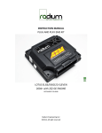
Installation Instructions for
30-3000 / 30-3001
Universal Water/Methanol
Injection Kit
,!
WARNING:
This installation is not for the electrically or mechanically
challenged! Use this system with EXTREME caution! If you are
uncomfortable with anything about this, please refer the
installation to an AEM trained tuning shop or call 800-423-0046
for technical assistance. You should also visit the AEM
Performance Electronics Forum at http://www.aempower.com
NOTE: AEM holds no responsibility for any engine damage that
results from the misuse of this product!
This product is legal in California for racing vehicles only and should never
be used on public highways.
ADVANCED ENGINE MANAGEMENT INC.
th
2205 126 Street Unit A, Hawthorne, CA. 90250
Phone: (310) 484-2322 Fax: (310) 484-0152
http://www.aempower.com
Instruction Part Number: 10-3000
© 2008 Advanced Engine Management, Inc
Page 1
Specifications
•
•
•
•
•
•
•
•
•
•
•
Ground output(optional).
1 Gallon reservoir (optional 5 Gallon) with integral level sensor.
150 PSI methanol compatible pump with integral check valve.
Progressive pump controller.
20-amp pump driver with over-current, over-voltage and under-voltage protection.
Error protection output with over-current, over-voltage and over-temperature protection.
Cockpit status LED for errors and low fluid.
Pump open and short detection and indication. Works even if the pump is off.
“Test” function that includes manual pump triggering.
Two dial pump speed control.
Battery voltage compensation.
Parts List:
Quantity
20 ft
1
1
1
1
Description
High Pressure ¼” Nylon Hose
1 Gallon Tank With Integral Fluid Level Sensor
10”h x 8.5”w x 4.25”d
150 PSI Pump With Hose Adapters
Progressive Injection Module
Check Valve
Mechanical Kit:
Quantity
60 in
36 in
1
10
8
4
4
4
1
2
9
1
Description
Vacuum Hose (7/64")
1/4" High Temp Wire Wrap
3/16" Tee Fitting
6” Zip Tie
Screw, Pan Head #8 x 1.0"
Screw, Pan Head #6 x 0.5"
Washer, #8 x 3/4"
Washer, #8 x 7/16"
5mm Cockpit LED
Butt Connector, 14-16 AWG (blue)
Butt Connector, 18-22 AWG (red)
1/4" Hose Routing Strip
Injector Nozzle Kit:
Quantity
1
1
1
2
Description
Stainless Injector Assy with Small (130ml/min) Jet
Stainless Jet, Medium (315ml/min)
Stainless Jet, Large (550ml/min)
Nylon Washer
Page 2
System Diagram
Pump and Tank Install
Find a suitable location to mount the tank and pump. See page 8 for the 5 gallon tank mounting
instructions. The pump should be mounted so the top of the tank is lower than the final injection
location. The pump should be mounted at or below the level of the tank. Use 4 of the 8 supplied
#8 sheet metal screws along with the 4 large washers to mount the 1-gallon tank.
Page 3
On the pump, note the directional arrows indicating fluid flow direction. Use the other 4 #8 sheet
metal screws along with the 4 small washers to mount the pump. The orientation of the pump is
not important, it will work regardless of position. Measure the distance between the fluid outlet
on the bottom of the tank and the fluid inlet on the pump. Make sure there are no sharp bends in
the hose. Cut the hose to length with a clean perpendicular slice, making sure the ends are
clean and flush. Push in the hose at the tank and pump to install. Make sure they are pushed in
all the way and check with a light tug on the hose. There is no need to tighten the preinstalled
pump fittings as they have been installed and leak checked at the factory. Secure the hose to
the chassis using sections of the supplied hose routing strip or with zip-ties.
Controller Install
Find a convenient location for the controller. The adjustment settings should remain in an
accessible location but still be protected from possible water incursion. If you need to extend
the wires to mount the controller use at least 14 AWG wire for the pump and controller ground
circuits and 18 AWG for the remainder. Use the 2 supplied #6 screws to mount the controller.
LED Install
Find a suitable location in the drivers line of sight to mount the status LED. Mount the LED and
run the wires to the controller. The LED indicates the operation of the controller. If the pump is
off and there are no errors the LED will be off. If there are no errors and the pump is on the
LED’s intensity will vary with the pump speed. If there are any errors they will be indicated by
flashing the LED.
Nozzle Selection and Assembly
Three jets are supplied with the kit. This ensures that regardless of your desired horsepower
you will not need to purchase additional jet sizes.
-1 (Small, 130 cc/min) is recommended for 150-250 HP
-2 (Med, 315 cc/min) is recommended for 250-400 HP
-3 (Large, 550 cc/min) is recommended for 400-650 HP
Page 4
The nozzle will come pre-assembled with the smallest jet. Regardless of your eventual
horsepower settings it is recommended that you start with this jet for your initial testing. The
nozzles are interchangeable and you can disassemble them for cleaning. If you find excessive
debris in the screen check your tank for contamination. When installing the screen it is only
necessary to be slightly tighter than finger tight. Do not over-tighten. The nylon washer included
is reusable but a spare is included for future servicing.
Select the location where the nozzle will be installed. It must be before (upstream of) the throttle
plate. If a MAF sensor is present, it must be placed between the MAF sensor and the throttle
plate. If an intercooler is present place the jet between the intercooler outlet and the throttle
plate. For the maximum cooling effect mount the nozzle toward the filter or turbo discharge.
Either weld on a 1/8” NPT bung or drill and tap a hole for the nozzle mounting. Measure the
length for the hose and cut. The Check Valve should be installed between the nozzle and the
pump. The closer to the nozzle the better. IMPORTANT: make sure the arrow on the valve body
is pointing towards the nozzle. Before installing the nozzle for the final time proceed to the
“Pump/System Check” stage to confirm proper operation.
Boost Pressure Hose
Find a location after the throttle plate to tap into your manifold pressure (boost). DO NOT hook it
up to the pressure at the turbocharger or at your boost controller. It must be after (downstream
of) the throttle plate. Use the supplied hose and “tee” if needed.
Variable Controller Installation
Fluid Level Switch (The switch has 2 black wires, the polarity is unimportant)
Black wire connects to Controller - Brown wire
Black wire connects to Controller - White wire
LED
Red wire connects to Battery Positive
Black wire connects to Controller - Gray Wire
Pump
Black wire connects to Controller - Orange wire.
Red wire connects to Battery Positive
Variable Pump Controller
Black wire connects to Battery Ground
Page 5
Red wire connects to Battery Positive
Yellow wire connects to Arm switch (+12V power to turn on the system)
Green wire(optional), Boost-Safe output for timing retard or boost dump solenoid. 1.7a Max
Blue wire (optional) 0-5vdc pressure signal. (.328v = 0psig, 5vdc = 38psig)
Pump/System Check
The “TEST” push button on the controller module can be used to test the system. Press and
hold the button to activate the pump. The pump speed will gradually increase from zero to full
speed over 6 seconds and then stop. When the button is released the controller will return to
normal operation.
After all wires are hooked up, add water to the tank and with the nozzle pointed into a container,
press and hold the test button. The flow will start gradually and increase to a steady amount. If
this happens then your system is connected properly. Check and repair any leaks. Drain the
water out of the tank and install the nozzle.
System Error Checking
Whenever a system error is encountered, the Boost-Safe output is enabled. All errors are
indicated by a flashing sequence of the status LED which can be determined by counting
flashes. Only one error can be counted with the higher priority at the top of this list:
Pump Driver Shorted
Trigger Condition: Current exceeding 15A on the driver output.
The status LED will flash a count of three and repeat. The pump driver will turn off to
protect itself and automatically retry every second. If the short is removed the controller will
function normally. Fluid flow is lost in this condition.
Pump Driver Open
Trigger Condition: Open circuit between pump drive and battery voltage.
The status LED will flash a count of two and repeat. The pump driver will continue to drive
the pump. If the open is repaired the controller will function normally. Fluid flow may be lost
in this condition.
Battery Voltage Out Of Range
Trigger Condition: Battery voltage is below 8.5V or above 16V.
The status LED will flash a count of four and repeat. The pump driver will turn off to protect
itself and automatically restart when the voltage returns to the normal range. Fluid flow is
lost in this condition.
Controller Tuning
The controller will monitor the manifold pressure, battery voltage, potentiometer settings, push
button and error conditions. Two potentiometers are used to set the pump PWM rate. The “Start
PSI” dial has a range from .5PSIg (full counterclockwise rotation) to 11PSIg(full clockwise
rotation). This is the pressure that the pump will start to operate. The “Full PSI” dial has a range
of 6PSIg (full counterclockwise rotation) to 38PSIg (full clockwise rotation). This is the pressure
that the pump will be running at full speed. Additionally, the controller will automatically correct
for battery voltage variations to give the same flow.
Page 6
Adjust the “Start PSI” value by setting the dial to approx 25% of the vehicles maximum boost.
Adjust the full-in value to your maximum boost (up to 38 PSIg of boost).
Error LED
The controller has an “ERROR” LED. This will mimic the operation of the cockpit LED. It will
flash out error codes as well as illuminate with varying intensity as a function of flow.
Short circuit testing
There are two modes of pump-driver short circuit protection available. One can detect a short at
any time but produces a slight buzzing in the pump. This should not be noticeable under most
conditions, but can be turned off if it is objectionable. If the less functional mode is chosen, then
a short can only be detected when the pump is running. Pressing and holding the “Test” button
while applying power toggles the mode. The change is acknowledged by a fast flashing (6
flashes and then repeats) of the status LED output and the on-board status LED. Once the
button is released the controller will continue to function normally. You can also tell what mode
has been selected by listening for the buzzing sound in the pump. Repeating this operation will
toggle between the two modes.
Boost-Safe Output (optional)
The progressive controller includes a Boost-Safe output (grounded when active) that activates
whenever the system is armed and runs out of fluid or an error code is flashing. The green wire
on the controller is the 1.7 amp switched ground. This wire can be hooked up to a solenoid that
will vent waste gate pressure when activated. Apply 12v to the other side of the solenoid (AEM
P/N 30-2400 or equivalent). This output can also be used to trigger a timing retard function in a
stand alone ECU or a CDI whenever the system runs out of fluid, thus protecting your engine.
Engine Tuning
A Water/Methanol mix will increase the charge density of your mixture. A significant amount of
the power gain available when using a water/methanol injection system is due to the fact that
the ignition timing may be increased due to the reduction in the tendency to knock. If the timing
is not advanced to take advantage of this benefit then the power gains available will be
substantially reduced. As always when tuning ignition advance, use small increments.
Page 7
Maintenance
The injector nozzle should be cleaned periodically. Disassemble the nozzle and clean it with a
suitable cleaner until all debris is removed. If excessive contamination is found check the rest of
the system for the source.
Optional 5 Gallon Tank (30-3001)
Parts List:
Quantity
1
4
4
8
Description
5 Gallon Tank With Integral Fluid Level Sensor
Bolt, Hex Head, 5/16-18 x 2” long
Nut, Ny-Lock, 5/16-18
Washer, 5/16
Mount the tank in an upright level position. Use the supplied 5/16-18 bolts, nuts, and large OD
flat washers for mounting the tank into your vehicle. IMPORTANT: Use the supplied large OD
washer to spread the load on the plastic mounting ears of the tank. DO NOT OVERTIGHTEN!
Nuts should just be snug, they are locking nuts and will not back out. Over-tightening will crack
the plastic and cause leaks and void the warranty.
AEM Electronics warranty
Page 8
Advanced Engine Management Inc. warrants to the consumer that all AEM High Performance
products will be free from defects in material and workmanship for a period of twelve (12)
months from date of the original purchase. Products that fail within this 12-month warranty
period will be repaired or replaced at AEM’s option, when determined by AEM that the product
failed due to defects in material or workmanship. This warranty is limited to the repair or
replacement of the AEM part. In no event shall this warranty exceed the original purchase price
of the AEM part nor shall AEM be responsible for special, incidental or consequential damages
or cost incurred due to the failure of this product. Warranty claims to AEM must be
transportation prepaid and accompanied with dated proof of purchase. This warranty applies
only to the original purchaser of product and is non-transferable. All implied warranties shall be
limited in duration to the said 12-month warranty period. Improper use or installation, accident,
abuse, unauthorized repairs or alterations voids this warranty. AEM disclaims any liability for
consequential damages due to breach of any written or implied warranty on all products
manufactured by AEM. Warranty returns will only be accepted by AEM when accompanied by a
valid Return Merchandise Authorization (RMA number. Product must be received by AEM
within 30 days of the date the RMA is issued.
Please note that before AEM can issue an RMA for any electronic product, it is first necessary
for the installer or end user to contact the EMS tech line at 1-800-423-0046 to discuss the
problem. Most issues can be resolved over the phone. Under no circumstances should a
system be returned or a RMA requested before the above process transpires.
AEM will not be responsible for electronic products that are installed incorrectly, installed in a
non approved application, misused, or tampered with.
Any AEM electronics product can be returned for repair if it is out of the warranty period. There
is a minimum charge of $50.00 for inspection and diagnosis of AEM electronic parts. Parts used
in the repair of AEM electronic components will be extra. AEM will provide an estimate of repairs
and receive written or electronic authorization before repairs are made to the product.
Page 9