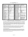
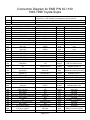
1
Installation Instructions for:
EMS P/N 30-1100
1993-1998 Toyota Supra TT
WARNING:
,!
This installation is not for the tuning novice nor the PC illiterate!
Use this system with EXTREME caution! The AEM EMS System
allows for total flexibility in engine tuning. Misuse of this
product can destroy your engine! If you are not well versed in
engine dynamics and the tuning of management systems or are
not PC literate, please do not attempt the installation. Refer the
installation to a AEM trained tuning shop or call 800-423-0046
for technical assistance. You should also visit the AEM EMS
Tech Forum at http://www.aempower.com
NOTE: AEM holds no responsibility for any engine damage that
results from the misuse of this product!
This product is legal in California for racing vehicles only and should
never be used on public highways.
ADVANCED ENGINE MANAGEMENT INC.
th
2205 126 Street Unit A Hawthorne, CA. 90250
Phone: (310) 484-2322 Fax: (310) 484-0152
Http://www.aempower.com
Instruction Part Number: 10-1100
© 2003 Advanced Engine Management, Inc.
Page 1 of 8
Congratulations! You have just purchased the finest Engine Management system for your car at any
price!
The AEM Engine Management System (EMS) is the result of extensive development on a wide variety of
cars. Each system is engineered for the particular application. The AEM EMS differs from all others in
several ways. The EMS is an all new stand alone system, which completely replaces the factory ECU and
features unique Plug and Play Technology, which means that each system is configured especially for
your make and model of car. There is no need to modify your factory wiring harness and in most cases
your car may be returned to stock in a matter of minutes. The AEMPro software is configured to work with
the factory sensors and equipment, so that there is no need for expensive or hard to find sensors, making
replacement and repairs as simple as with an unmodified car. For stock and some slightly modified cars,
the AEMPro software will be preprogrammed with a set of base parameters, providing a starting point for
individual tuning. For more heavily modified cars, the EMS has many spare inputs and outputs allowing
the elimination of separate rev-limiters, boost controllers, nitrous controllers, and fuel computers. It will
also allow programmable control over all automatic transmission functions, and includes a configurable
onboard data logger capable of recording 512kb of information. Every EMS comes with all functions
installed and activated, and there are no expensive options or upgrades to be performed.
The installation of the AEM ECU on the 1993-1998 Toyota Supra uses the stock sensors and actuators.
The base map is automatically installed in the calibrations directory in the AEMPro directory on your
computer. It is named 1100.V1.00.CAL.
Full details of the test vehicle used to generate this map can be found in the files notes section. However,
while the base map is a good starting point and may save you considerable time and money, it will not
replace the need to tune your specific application. It is not intended to be driven aggressively. Ignoring
this can and will damage your engine.
The factory Supra traction control is not supported with the AEM EMS. No removal of components or
other action is required from the end user. The ignition control is converted to “wasted spark” with 3
drivers controlling the six factory coils. The 30-1100 EMS pin out and connector diagram is at the end of
this document .
Please visit the AEM EMS Tech Forum at http://www.aempower.com and register. We always post the
most current strategy release, PC Software and base calibrations online. On the forum, you will find many
helpful hints/tips to make your EMS perform it’s best.
Read and understand these instructions BEFORE attempting to install this product.
1) Removing the Stock Engine Control Unit
a) Access the stock Engine Control Unit (ECU). The location of the ECU on the Toyota Supra is
under the passenger firewall carpet and has a black cover that is removed by 4 10 mm nuts.
b) Carefully disconnect the wiring harness from the ECU. Avoid excessive stress or pulling on the
wires, as this may damage the wiring harness. Some factory ECU’s use a bolt to retain the
factory connectors, and it must be removed before the harness can be disconnected. There may
be more than one connector, and they must all be removed without damage to work properly with
the AEM ECU. Do not cut any of the wires in the factory wiring harness to remove them.
c) Remove the fasteners securing the ECU to the car body, and set it aside. Do not destroy or
discard the factory ECU, as it can be reinstalled easily for street use and troubleshooting.
d) Make sure any aftermarket electronics are COMPLETELY and properly removed before starting
the vehicle.
2) Install the AEM Engine Management System.
a) Plug the factory wiring harness into the AEM ECU, and position it so that the wires are not pulled
tight or stressed. Secure it with the provided Velcro fasteners.
b) Plug the comms cable into the EMS and into your PC.
c) Turn your ignition on but do not attempt to start the engine.
d) Upload the base calibration file (.cal) that most closely matches your vehicle’s configuration.
(These files can be found in the AEMPro/Calibrations/Toyota folder on your computer’s hard
drive)
e) Set the throttle range: Select the Configure drop down menu, then ECU Setup | Set Throttle
Range and then follow the direction given on the screen.
Page 2 of 8
f)
Verify the ignition timing by selecting the Configure drop down menu, then ECU Setup | Set
Ignition. Use a timing light and compare the physical timing numbers to the Parameter Ignition
Timing displayed. Use the Advance/Retard buttons to make the timing number match.
3) You are now ready to begin tuning your vehicle.
a) Note: This calibration needs to be properly tuned and is not recommended for street use. NEVER
TUNE YOUR VEHICLE WHILE DRIVING.
Page 3 of 8
Application Notes for EMS P/N 30-1100
1993-1998 Supra
Make:
Model:
Years Covered:
Engine Displacement:
Engine Configuration:
Firing Order:
N/A, S/C or T/C:
Load Sensor Type:
Map Min:
Map Max:
# Coils:
Ignition driver type:
How to hook up a CDI:
# Injectors:
Injector Flow Rate:
Injector Resistance:
Injection Mode:
Knock Sensors used:
Lambda Sensors used:
Idle Motor Type:
Main Relay Control:
Crank Pickup Type:
Crank Teeth/Cycle:
Cam Pickup Type:
Cam Teeth/Cycle:
Transmissions Offered:
Trans Supported:
Drive Options:
Notes:
Toyota
Supra
* 1993-1998
3.0L
I6
1-5-3-6-2-4
N/A (93-97)TT (93-98)
MAP
1.09v @ -11.7 PSI
4.98V @ 18.3 PSI
** 6
0-2.5V Logic
Wire after igniter
6 (Inj 1-6)
550 cc/min
2.3 Ω
Sequential
1&2
1&2
Stepper
Yes
Mag
24
Mag
1
M/T, A/T
M/T ,A/T
RWD
Supplied Connectors:
Spare Injector Drivers:
Spare Injector Drivers:
Spare Injector Drivers:
Spare Injector Drivers:
Spare Injector Drivers:
Spare Injector Drivers:
Spare Coil Drivers:
Spare Coil Drivers:
Spare Coil Drivers:
Spare Coil Drivers:
Boost Solenoid:
EGT #1 Location:
EGT #2 Location:
EGT #3 Location:
EGT #4 Location:
Spare 0-5V Channels:
Spare 0-5V Channels:
Spare 0-5V Channels:
Spare Low Side Driver:
Spare Low Side Driver:
Spare Low Side Driver:
Spare Low Side Driver:
Check Engine Light:
Spare Switch Input:
Spare Switch Input:
A/C Switch Input:
Clutch Switch Input:
Spare pins
Inj #10, Pin A11
Inj #7, Pin 70B
----------------PW #2, Pin 60B
Pin 2B
Pin 4B
Pin 8B
Pin 67B
Ftemp 24B (sp on M/T)
--Low Side #8, Pin 61B
Low Side #9, Pin 68B
Low Side #11, Pin 59B
Low Side #10, Pin 6A
Switch #6, Pin 22B
Switch #2, Pin 23B
PR Press, Pin 34A
Wire with relay
Installation notes for 30-1100 ECU on Toyota Supra Twin Turbo.
The installation of the AEM ECU on the Toyota Supra TT converts the ignition system to a wasted spark
system. This change in ignition strategy requires reducing the spark plug gap to .025”. With standard
spark plugs, the reduction in plug gap may cause poor idle quality unless the mixture is run richer than
12.5:1 AFR and the ignition timing is reduced to 11 degrees BTDC. We have found that the use of the
Denso Iridium Power spark plugs (IQ24 or IQ26) eliminates the idle quality issue when using reduced
plug gaps. Additionally, these spark plugs have proven to perform exceptionally well when used in
moderate to high boost applications.
The Mass air flow sensor is not used as the load input for calibration from AEM. Due to the substantial
increase in power by removing the AFM, AEM recommends using a map sensor in speed density
measurement. The factory map sensor is good for up to 230 kpa (18 psi) of boost. Above this pressure, it
is recommended to use a 3 bar map sensor or higher (Contact AEM for part numbers).
Auto Transmission Operation
The Wide open throttle shift RPM is based upon when the ECU sends the command to perform the gear
change, this DOES NOT mean it will shift at that exact RPM due to mechanical response times for the
hydraulic fluid to affect the change. You will have to determine the response time for your transmission by
observing the engine speed vs. shift event in AEMLog and adjusting the shift point to occur before the
engine reaches maximum rated engine speed.
Page 4 of 8
Connection Diagram for EMS P/N 30-1100
1993-1998 Toyota Supra
PnP
Available
Dedicated
Pin #
1A
2A
3A
4A
5A
6A
7A
8A
9A
10A
11A
12A
13A
14A
15A
16A
17A
18A
19A
20A
21A
22A
23A
24A
25A
26A
27A
28A
29A
30A
31A
32A
33A
34A
35A
93-98 Supra 2JZGTE
Switched 12v at key on
Vehicle Speed Sensor
Kickdown switch (Not Used)
Brake switch input (12V) Not Used
NOT USED
Malfunction Indicator Lamp (LS10)
Reverse indicator input (ADR13)
HS1 Output
2nd gear indicator input (ADR13)
Auto only
1st gear indicator input (ADR13)
Auto only
NOT USED
NOT USED
NOT USED
NOT USED
NOT USED
LS7 (USED FOR CLIMATE
CONTROL)
TT For DATALINK connector(Injector
10i)
Manual trans mode selector switch
(Switch #5)
TE2 to DATALINK connector
(Injector 9i)
TE1 For DATALINK connector (PW1)
NOT USED
Fuel pump control (Coil 4))
ACMG to A/C Magnetic clutch (LS6)
Activates Main Relay with 12V signal
at key on
Manual indicator mode light output
(FM) Auto only
NOT USED
NOT USED
Over Drive Switch input (Switch #4)
NOT USED
HS2
Switched 12v from Main Relay
NOT USED
12V constant battery
A/C to a/c amplifier(ADR11 set to pin
# -9 for a/c control)
NOT USED
The Plug and Play system comes with this configured for proper operation
of this device. Is still available for reassignment by the end user.
The function is not currently allocated and is available for use
The location is fixed and can not be changed
AEM P/N 30-1100 Name
SWITCHED 12V
Vehicle Speed
N/U
N/U
N/U
LS10
GEAR
HS1
I/O
Input
Input
N/U
N/U
N/U
Output
Input
Output
GEAR
Input
GEAR
N/U
N/U
N/U
N/U
N/U
Input
N/U
N/U
N/U
N/U
N/U
Availability
Dedicated
Dedicated
Not used
Not used
Not used
PNP for Check Engine light
PNP reverse input (Auto Only)
Available +12v switched
PNP 2nd gear indicator (auto
only)
PNP 1st gear indicator (auto
only)
Not used
Not used
Not used
Not used
Not used
LS7
Output
PNP for climate control
INJECTOR 10I
Output
available injector 10
Swtich #5
Input
Manual trans mode (auto only)
INJECTOR 9I
PW 1
N/U
Coil 4
LS6
Output
Output
N/U
Output
Output
available injector 9
available pw1
Not used
PNP fuel pump activation
PNP A/C compressor relay
COIL 5
Output
FM
N/U
N/U
Switch #4
N/U
HS2
Switched Power
N/U
12V CONSTANT
Output
N/U
N/U
Input
N/U
Output
Input
N/U
Input
Dedicated Main relay
PNP manual mode indicator
(auto only)
Not used
Not used
PNP Overdrive input (auto only)
Not used
Available +12v switched
Dedicated
Not used
Dedicated
PR Press
N/U
Input
N/U
PNP input for a/c request
Not used
Page 5 of 8
36A
37A
38A
39A
40A
NOT USED
NOT USED
NOT USED
NOT USED
NOT USED
N/U
PW2
N/U
N/U
N/U
N/U
N/U
N/U
N/U
N/U
Not used
Not used
Not used
Not used
Not used
1B
2B
Timing (speed sensor) ground
EGT # 1 (+) (ADR 17)
SP2 - Timed Speed input ground
Vehicle speed sensor
EGT # 2 (+) (ADR18)
Cam Sensor 2 (G2) Ground
Cam Sensor 1 (G1) Ground
Crank Sensor (NE) Ground
EGT # 3 (+) (ADR15)
Auto Trans Sol No2 (HS3)S2
Auto Trans Sol No1 (HS4)S1
O2 Sensor ground
Auto Trans Sol No5 (Line Pressure)
(Idle 7)
Auto Trans Sol No4 (Engagement
Speed) (Injector 8)
Auto Trans Sol No3 (Converter Lock
up) (Idle 5))
Injector 6
Injector 5
Injector 4
Injector 3
Injector 2
Injector 1
Input Shaft Speed sensor signal
(Switch #2)
Switch #6 input
Tail Shaft Speed sensor (Switch #3)
Auto Trans Fluid Temp or spare
temp Sensor input (ADR14)
Cam Sensor 2 (G2) Input
Cam Sensor 1 (G1) input
Crank Sensor (NE) input
Sensor Ground
(PW1i) ran through VF1 for
DATALINK connector
NOT USED
Auto Trans Sol No5 (SLT+) (Idle 8)
Idle 4
Idle 1
Idle 3
Idle 2
NOT USED
Not available on automatic
VSV For exhaust bypass valve (LS4)
Spare output if Single Turbo
VSV For Exhaust gas control valve
(LS5) Spare output if single Turbo
TGND
EGT #1
Output
Input
Dedicated
Available EGT input
TGND
EGT #2
TGND
TGND
TGND
EGT #3
HS3
HS4
oxgnd2
Output
Input
Output
Output
Output
Input
Output
Output
Output
Dedicated
Available EGT input
Not used
Dedicated
Dedicated
Available EGT input
PNP Auto Trans sol #2
PNP Auto Trans sol #1
Dedicated
IDLE7
Output
INJECTOR 8
Output
PNP Auto line pressure
PNP Auto gear engagement
speed
IDLE5
INJECTOR 6
INJECTOR 5
INJECTOR 4
INJECTOR 3
INJECTOR 2
INJECTOR 1
Output
Output
Output
Output
Output
Output
Output
PNP Auto Converer Lockup
Dedicated
Dedicated
Dedicated
Dedicated
Dedicated
Dedicated
Swich #2
Switch #6
Switch #3
Input
Input
Input
Available Switch input
Available Switch input
Available Switch input
FTEMP
Spare Speed
CAM
CRANK
SENSOR GROUND
Input
Input
Input
Input
Output
PNP trans temp sensor
Available spare speed
Dedicated
Dedicated
Dedicated
pw1outi
N/U
IDLE8
IDLE4
IDLE1
IDLE3
IDLE2
N/U
IDLE 6
Output
N/U
Output
Output
Output
Output
Output
N/U
Output
Available Pulse width
Not used
PNP Auto trans line pressure
PNP Idle control motor
PNP Idle control motor
PNP Idle control motor
PNP Idle control motor
Not used
Available idle driver
LS4
Output
PNP for EBP on stock twins
LS5
Output
PNP for EGC on stock twins
3B
4B
5B
6B
7B
8B
9B
10B
11B
12B
13B
14B
15B
16B
17B
18B
19B
20B
21B
22B
23B
24B
25B
26B
27B
28B
29B
30B
31B
32B
33B
34B
35B
36B
37B
38B
39B
Page 6 of 8
40B
41B
42B
43B
44B
45B
46B
47B
48B
49B
50B
51B
52B
53B
54B
55B
56B
57B
58B
VSV For intake air control (LS3)
Spare output if single Turbo
5V Reference
NOT USED
TPS signal input
Coolant Sensor Input
Air Temp Sensor (ADR6)
NOT USED
AFR#1
AFR#2
Knock 2 input (Rear Knock Sensor)
Knock 1 input (Front Knock Sensor)
NOT USED
Ignitor 6 (Coil 1)
Ignitor 5 (Coil 2)
Ignitor 4 (Coil 3)
Ignitor 3 (Coil 3)
Ignitor 2 (Coil 2)
Ignitor 1 (Coil 1)
NOT USED
LS3
5V REFERENCE
N/U
TPS
COOLANT
Air Temp
N/U
LAMBDA1
LAMBDA2
KNOCK2
KNOCK1
N/U
COIL1
COIL2
COIL3
COIL3
COIL2
COIL1
N/U
Output
Output
N/U
Input
Input
Input
N/U
Input
Input
Input
Input
N/U
Output
Output
Output
Output
Output
Output
N/U
59B
60B
LS11
Boost Control (PW2)
LS11
PW2OUT
Output
Output
61B
62B
63B
64B
65B
LS8
Map Sensor Input
NOT USED
NOT USED
Sensor Ground
Spare 0 to 5v input (was MAF sensor
input)
EGT 4 (+) (ADR16)
LS8
MAP
N/U
N/U
SENSOR GROUND
Output
Input
N/U
N/U
Output
MAF
EGT #4
Input
Input
LS9
Chassis Ground
Injector 7
Ox 1 Heater Ground (LS12) or Spare
output if wideband used
Ox 2 Heater Ground (LS2) or spare
output if Wideband used
Fuel Pressure up VSV or Spare
output (LS1)
EVAP or Secondary injector or spare
switched output (Injector 9)
EGR or Secondary injector or
switched output (Injector 10)
Neutral Starting switch (ADR13)
NOT USED
Ground
Chassis Ground
Chassis Ground
LS9
RTN
INJECTOR 7
Output
Output
Output
Available 0to5v
Available EGT
Available Switched Ground
1.5amp max
Dedicated
Available Inj driver 1.5 amp max
LS12
Output
PNP O2#1 Heater
LS2
Output
PNP O2#2 Heater
LS1
Output
PNP fuel pressure up VSV
INJECTOR 9
Output
PNP for EVAP control
INJECTOR 10
Gear
N/U
RTN
RTN
RTN
Output
Input
N/U
Output
Output
Output
PNP for EGR control
PNP for Neutral indicator
Not used
Dedicated
Dedicated
Dedicated
66B
67B
68B
69B
70B
71B
72B
73B
74B
75B
76B
77B
78B
79B
80B
Page 7 of 8
PNP for IAC for stock twins
Dedicated
Not used
Dedicated
Dedicated
Dedicated
Not used
Dedicated
Dedicated
Dedicated
Dedicated
Not used
Dedicated
Dedicated
Dedicated
Dedicated
Dedicated
Dedicated
Not used
Available Switched Ground
1.5amp max
PNP for boost control
Available Switched Ground
1.5amp max
Dedicated
Not used
Not used
Dedicated
AEM Electronics Warranty
Advanced Engine Management Inc. warrants to the consumer that all AEM Electronics
products will be free from defects in material and workmanship for a period of twelve
months from date of the original purchase. Products that fail within this 12-month
warranty period will be repaired or replaced when determined by AEM that the product
failed due to defects in material or workmanship. This warranty is limited to the repair or
replacement of the AEM part. In no event shall this warranty exceed the original
purchase price of the AEM part nor shall AEM be responsible for special, incidental or
consequential damages or cost incurred due to the failure of this product. Warranty
claims to AEM must be transportation prepaid and accompanied with dated proof of
purchase. This warranty applies only to the original purchaser of product and is nontransferable. All implied warranties shall be limited in duration to the said 12-month
warranty period. Improper use or installation, accident, abuse, unauthorized repairs or
alterations voids this warranty. AEM disclaims any liability for consequential damages
due to breach of any written or implied warranty on all products manufactured by AEM.
Warranty returns will only be accepted by AEM when accompanied by a valid Return
Merchandise Authorization (RMA) number. Product must be received by AEM within 30
days of the date the RMA is issued.
Please note that before AEM can issue an RMA for any electronic product, it is first
necessary for the installer or end user to contact the tech line at 1-800-423-0046 to
discuss the problem. Most issues can be resolved over the phone. Under no
circumstances should a system be returned or a RMA requested before the above
process transpires.
AEM will not be responsible for electronic products that are installed incorrectly,
installed in a non approved application, misused, or tampered with.
Any AEM electronics product can be returned for repair if it is out of the warranty period.
There is a minimum charge of $50.00 for inspection and diagnosis of AEM electronic
parts. Parts used in the repair of AEM electronic components will be extra. AEM will
provide an estimate of repairs and receive written or electronic authorization before
repairs are made to the product.
Page 8 of 8